Università Politecnica delle Marche
Scuola di Dottorato di Ricerca in Scienze dell’Ingegneria Curriculum in Ingegneria Civile, Ambientale, Edile ed Architettura ---
Applications of innovative materials,
GFRP and structural adhesives, for the
curtain wall: technological and
performance verification.
Ph.D. Dissertation of: Vanessa Terlizzi Advisor:
Prof. Placido Munafò Prof. Francesca Stazi
Università Politecnica delle Marche
Dipartimento di Ingegneria Civile, Edile ed Architettura (DICEA) Via Brecce Bianche — 60131 - Ancona, Italy
In breve
L’obiettivo del presente lavoro è verificare l’applicabilità di materiali innovativi, quali compositi (GFRP - Glass Fibre Reinforced Polymer) e colle strutturali, per la realizzazione di facciate continue ad alte prestazioni meccaniche e termiche e a basso impatto ambientale. Tale obiettivo è stato verificato anche tramite l’applicazione del principio della “Semplificazione tecnologica” che rappresenta il filo conduttore alla base dello studio e delle sperimentazioni svolte dal gruppo di ricerca, coordinato dal Prof. P.Munafò, che ha sviluppato il brevetto “Sistema per la realizzazione di facciate di edifici” (n. 102015000087569) di cui il Professore è inventore. Con tale filosofia di approccio è possibile realizzare componenti edilizi altamente prestazionali e semplici nella loro concezione essendo costituiti con un numero limitato di pezzi implicando così un minor consumo di energia nella produzione, assemblaggio, manutenzione e smaltimento del prodotto, classificandolo quindi come eco-sostenibile.
In questa tesi viene verificata la fattibilità di un sistema costruttivo per la realizzazione di facciate continue per edifici studiando preventivamente, con test sperimentali e analisi sul ciclo di vita dei componenti, le prestazioni meccaniche dei profili in GFRP e degli adesivi strutturali in condizioni di invecchiamento accelerato (durabilità) e non, e l’interazione del componente edilizio con l’ambiente, dalla produzione alla dismissione finale (LCA - Life Cycle Assessment).
I metodi principalmente usati in questo studio sono di tipo sperimentale al fine di testare le proprietà meccaniche dei materiali, in condizioni ambientali e dopo invecchiamento (accelerato in camera climatica ad elevata umidità e temperatura (ISO 6270-2) e sotto esposizione ai raggi UV (ASTM D904–99)). In seguito ai singoli test di invecchiamento precedentemente citati, sono stati condotti ulteriori sperimentazioni riguardanti il trattamento di campioni a condizioni di invecchiamento combinato (camera climatica ed esposizione ai raggi UV - Tcc+Tuv - e viceversa - Tuv+Tcc -). Al fine di validare i risultati ottenuti dalle sperimentazioni effettuate sono stati eseguiti test numerici e analitici.
Il risultato più significativo è dato proprio dalla validazione dell’idea brevettuale dimostrando la possibilità di industrializzare componenti (facciate continue) che utilizzano tale materiale composito (pultruso - GFRP), mediante l’accoppiamento a materiali come l’acciaio che possono conferire al componente alte prestazioni meccaniche, soprattutto per quanto riguarda il contenimento delle deformazioni sotto carico.Le soluzioni tecniche studiate inoltre evitano il problema della rottura fragile delle giunzioni bullonate che è uno dei problemi che riguardano le giunzioni di questo tipo su profili in pultruso. La deformabilità e la rottura fragile delle giunzioni bullonate dei profili in pultruso ne hanno limitato l’utilizzo nel settore dell’ingegneria edile per la realizzazione di facciate continue specie di grandi dimensioni. A tal fine l’attività di ricerca è stata prevalentemente incentrata a verificare la possibilità di inserire nei montati in pultruso di tali facciate, una lamina d’acciaio incollata per contenere la deformazione e per migliorare la qualità della giunzione bullonata in modo da evitare rotture di tipo fragile raggiunto il carico di collasso. Le risultanze dei test sperimentali condotti dimostrano le buone performance del sistema ibrido GFRP-acciaio anche in seguito all’esposizione a differenti condizioni di invecchiamento artificiale e verificano la fattibilità di realizzazione di una facciata continua ad alte prestazioni meccaniche e termiche.
Abstract
The aim of this work is to demonstrate the applicability of innovative materials, such as Glass Fibre Reinforced Polymer (GFRP) industrialized components (profiles), structural adhesives, for the realization of curtain walls with high mechanical and thermal performances and low environmental impact.
This objective with the “Technological Simplification” principle is verified. This latter is the guiding principle to the base of the search and experimental tests carried out by the research group. The teamwork coordinator and patent inventor is Prof P.Munafò, with him I developed a “System for the realization of building façade” (n. 102015000087569).
The “Technological Simplification” principle allows the building components realization with high performance and easy to assemble, by using a limited number of pieces. All this involves lower energy consumption in the production, assembly, maintenance and disposal phases. For this reason, the construction element can be considered environmentally sustainable.
In this thesis, the feasibility of the constructive system for the realization of building façade, through the experimental tests and component life cycle analysis, is verified. The components and materials properties both in laboratory conditions and after different types of ageing conditions (durability) are tested. The interaction between building components and environment, from the production to ultimate disposal (LCA - Life Cycle Assessment) are analysed.
The methods used were mostly of the experimental type. The material mechanical properties both in environmental conditions and in different types of ageing conditions were analysed, such as continuous condensation (ISO 6270-2) and UV irradiation (ASTM D904–99). Additional test with combined artificial ageing (climatic chamber and exposure to UV radiation - Tcc+Tuv – and the other way around - Tuv+Tcc) were tested.
The numerical and analytical studies were carried out, with the objective to check and validate the results obtained through experimental tests.
The main outcome was the validation of the patents basic ideas, which is a key point in the industrialization process of the construction elements (Structural Member). The aim of this work is to demonstrate the feasibility of the use of pultruded Glass Fiber Reinforced Polymers (GFRP) profiles, adhesively joined with other materials (i.e. steel), in the construction sector. The objective is both to reduce the GFRP profiles deformation under loading conditions, and to avoid the brittle fractures that could occur in bolted joints. In the building engineering field, in fact, these issues (deformations and brittle fractures) prevent the use of pultruded materials. In the research activity, the possibility to adhesively join a steel laminate on the pultruded profile mullion for curtain walls was verified. The containment of the deformations and the prevention of brittle fractures in the bolted joint were checked, in order to verify the pultruded curtain wall feasibility, both constructively and for its structural and energy performances.
Experimental results, in fact, demonstrated that the use of GFRP profiles, bonded with structural adhesives and combined with steel, is successful on curtain walls, even when they are exposed to adverse environmental conditions. The feasibility of the curtain wall implementation with high performance is verified.
Abstract
Contest
1. Overall introduction1.1. Objective 1.2. Literature review
1.3. Analysis of GFRP and aluminium profiles: market and patents 1.4. Legislation
1.5. References
2. The research results: “Sistema per la realizzazione di facciate di edifici”, patent for curtain wall
2.1. State of art
2.2. The patent application n. 102015000087569 2.3. Product information
2.4. List of figure
3. On GFRP-steel hybrid bonding systems: mechanical performances before and after the ageing treatments.
3.1. Abstract 3.2. Introduction 3.3. Methods
3.3.1. Phases
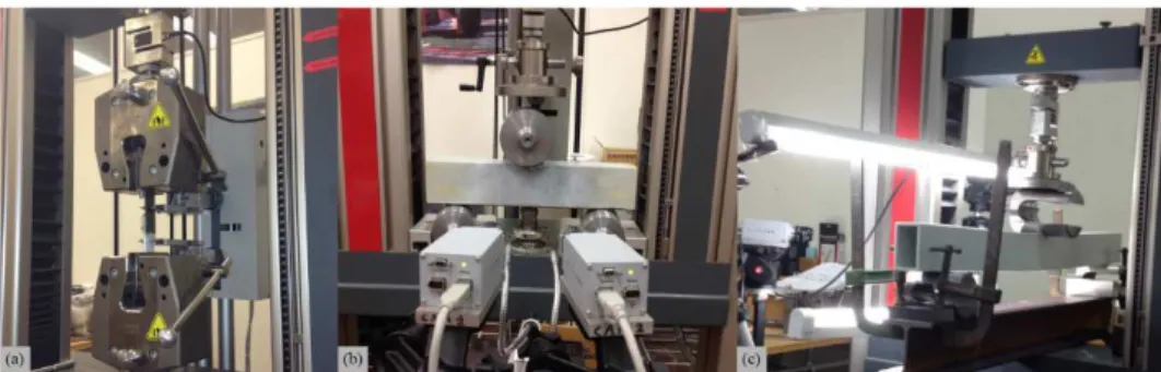
3.3.2. Experimental tests
3.3.2.1. Material characterization tests 3.3.2.2. Mechanical tests 3.3.2.3. Artificial ageing 3.3.3. Analytical studies 3.4. Experimental results 3.4.1. Shear tests 3.4.1.1. Mechanical performance 3.4.1.2. Failure modes 3.4.2. Puncture tests 3.4.2.1. Mechanical performance 3.4.2.2. Failure modes
3.4.3. Three-point bending tests
3.4.3.1. Mechanical performance 3.4.3.2. Failure modes 3.5. Analytical results 3.6. Discussion 3.7. Conclusions 3.8. Reference
3.9. List of tables and figures
4. Technological and performance verification through SimaPro and Midas Gen software
4.1. Introduction
4.2. Life cycle assessment methodology
4.2.1. Comparative life cycle assessment between an aluminium and GFRP-steel façade
4.2.2. Results and discussion
4.3. Modelling and comparison between a traditional material and GFRP-steel façade through Midas Gen software
4.3.1. Results and discussion 4.4. Conclusion
4.5. References
4.6. List of tables and figures 5. Market investigation
5.1. Curtain wall market
5.1.1. The European market 5.1.2. The USA market 5.1.3. The Italian market
5.1.3.1. The market sector 5.1.3.2. The possible competitors 5.1.3.3. The possible customers
5.1.3.4. Production costs and sales price 5.2. References
5.3. List of tables and figures 6. Conclusion and unresolved issues
Appendix 1. Fibre Reinforced Polymers
1.1. Composite materials – FRP and GFRP 1.2. Benefits and features of FRP materials 1.3. Classification of FRP materials 1.3.1. The matrix 1.3.1.1. Thermoset resins 1.3.1.2. Thermoplastic resins 1.3.2. Reinforcements 1.3.2.1. Reinforcement forms 1.4. The surface interaction of fibre and resin 1.5. The pultrusion process
1.6. References 1.7. List of figures Appendix 2. Adhesives 2.1. Adhesives 2.2. Benefits of adhesives 2.3. Classification of adhesives
2.3.1. Load carrying capacity 2.3.1.1. Structural
2.3.1.2. Semi-structural and non-structural 2.3.1.3. Pressure sensitive 2.3.2. Cure mechanisms 2.3.2.1. Physically hardening 2.3.2.2. Chemically curing 2.3.2.3. Pressure sensitive 2.3.3. Forms 2.4. Epoxy adhesives
2.5. Glass transition temperature 2.6. Reference
2.7. List of figures Annexes
1
Chapter 1
Overall introduction
1.1.
Objectives
The aim of the Ph.D. research is to assess the applicability of pultruded Glass Fiber Reinforced Polymers (GFRP) profiles, adhesively joined with other materials (i.e. steel), for the realization of curtain walls with high mechanical and thermal performances and low environmental impact. Furthermore, the study from the design phase to the industrialization process to transfer these innovative elements to the construction market is carried out. In the recent years, the working group has designed and patented the Structural Member for curtain walls (patent application n. 102015000087569). The guiding principle is mainly the “Technological Simplification” a method to realize high-performance and easy to assemble components, by using innovative materials in a limited number of pieces. This principle led to low energy consumption in the production, assembly, maintenance and disposal processes, becoming the new concept of “environmental sustainability” [1].
The aim of this work is to demonstrate the feasibility of the ideas behind the patented Structural Member, both constructively and for its structural and energy performances. Especially, the possibility to adhesively join a steel laminate on the pultruded profile mullion for curtain walls in order to contain the deformations (under loading condition) and the prevention of brittle fractures in the bolted joint is discussed also considering the durability of construction element.
The main aspects of this work concern the mechanical performance of the hybrid system, GFRP-steel, and of the structural adhesives for the realization of the mullion for curtain walls; the energy performance through LCA process (UNI EN ISO 14040) for to analyse the curtain wall life cycle and its environmental impact for a period of 30 years. This report is structured as follows:
(i) State of the art about the curtain wall (construction element, patent, literature review);
(ii) Structural Member patent, description and product information;
(iii) An experimental and analytical study regarded the comparison of different epoxy adhesives used in GFRP-steel profiles conjunctions: the objective was to verify the compatibility of the two materials and the steel contribute to the stiffness increase of GFRP profiles. The verification of the hybridization method was conducted through several mechanical tests and the effects of different aging conditions were observed;
(iv) Mechanical and thermal performance verification of the curtain wall made in pultruded profiles;
(v) Market analysis; (vi) Conclusion.
2
1.2.
Literature review
In recent years, in civil engineering, increasing attention has been focused on technologies and innovative materials that allow achieving both excellent mechanical performance and maximum energy efficiency. Furthermore, increasing interest has also been pointed towards technological simplification. The reduction of the number of components leads to numerous advantages: the ease of installation, the saving of production time and the decrease of environmental impacts, thanks to the reduction of production processes and the relative CO2 emissions [1]
Over the past two decades, glass fiber reinforced polymer (GFRP) pultruded profiles are becoming a valuable alternative in many civil engineering fields as in structures of building and bridges, in both new construction and rehabilitation [2], electricity transmission tower [3], and windows frames [4], [5].
- GFRP characteristics
In literature, many studies were carried out to investigate the different mechanical properties of composite material in un-aged conditions, both on small samples: flexural [6], [7], torsional [8], tensile [9] and compressive [10] characteristics, and on full-scale components: connections [11], profiles [12] or panels [13]. Further experiments were performed to compare profiles with different types of the matrix [14], [15], demonstrating that the vinyl ester resin has better mechanical properties than the polyester one.
With regard to the durability, different aged conditions were carried out in various experimental studies: the exposure to UV radiations on the GFRP profiles, led to very small changes in the mechanical properties[15]–[17], while the “hot-wet” environmental have an adverse effects. Many authors investigated the effects of the immersion in demineralized [15], [16] [18]–[22] and salt [15], [19]–[22] water. Some studies also compared degradation under both artificial and natural aging [14], [17], [21]. However, comprehensive and validated data are still scarce, a large scatter and contrasting data in the results are observed, even if similar methodologies are used.
The durability effects were analysed also in the adhesively bonded joints (other aspect of this research) which are the subject of several types of research. The mechanical behaviour [23], failure modes [24]–[27] and the effect of the joint geometry on the structural response [28]– [30] were investigated. Regarding environmental effects, most of the studies focused on adhesively-bonded joints for aerospace and automotive engineering, nonetheless there are some papers that shifted their attention to the civil engineering field. For example, Zhang et al. [31], [32] demonstrated that high temperatures lower the mechanical performance of bonded joints, especially when the glass transition temperature of the adhesive is reached. This phenomenon is even more pronounced with high humidity levels.
However, validated data about the properties of adhesives used to connect pultruded materials are still scarce. Furthermore, there is a lack of understanding of the aging degradation mechanisms suffered by different types of adhesives used in GFRP joints. Additional characteristics were considered in order to use the GFRP for the civil construction: fire protection, rehabilitation and sustainable solution.
Some authors [33]–[35] studied the viability of using GFRP pultruded profiles in civil field, experimental investigations were carried out to analyse their mechanical behaviour when exposed to fire (high temperature). Other search has been focused on the rehabilitation and reconstruction in order to restore the functionality of deteriored structural components as concrete mullion for Toronto school facades [36] and bridge decks [37]
- GFRP and steel in comparison
In this work, the adhesive structural and steel laminated used in order to increase the performance mechanical (stiffness) and reduce deformations of the GFRP structural member are investigated.
3 This innovative composite material is characterized by several advantages: high specific strength, lightweight, low thermal and electrical conductivity, non-corrodibility.
Moreover, even though a GFRP structure is significantly more expensive than a similar steel structure, an actual economic advantage can be obtained in the maintenance and durability, when life cycle cost is accounted for [3].
Nevertheless, compared to steel, this material presents various disadvantages. GFRPs are profiles with a high fiber content and, unlike metals, their stiffness and strength depend on the orientation of the fibers. This orthotropic nature necessarily requires the availability of data on mechanical properties that nowadays is still lacking [38]. In addition, the brittle character of the composite material determines the difficulty of realizing bolted joints. Bolting, in fact, is a not material-adapted way to connect [39], because adherents are subjected to drilling operations that cut the fibers. In this case steel-adhesive connection on GFRP represents the most efficient jointing method, leading to a more uniform load transfer [23, 31, 40] and to avoid the brittle fracture. However this kind of connection is strongly influenced by environmental conditions, which can reduce mechanical properties of the adhesives and, generally, of the adherents.
Furthermore the low elastic modulus (up to ten times lower) [41–44], and the consequent high deformability under loading conditions of the GFRP profiles impede the applications of this composite material in structures with large spans [45–47], especially when small profiles size is required, such as in curtain walls.
For this reason, it is necessary to develop suitable approaches to improve the stiffness of the GFRP pultruded material, and some authors demonstrate that coupling GFRP profiles with higher mechanical performances materials – i.e. hybridization system - is an advantageous method [41, 48, 49].
Kim and Lee [45] developed a steel-reinforced hybrid GFRP deck panel for temporary bridges. The results confirmed that the flexural stiffness of the GFRP deck panel was effectively increased by the proposed methods of hybridization. Wu et al. [41] explored two strengthening methods to improve the bearing capacities of GFRP pultruded SHS sections, by bonding alternatively CFRP plates and steel sections on the external surfaces of the GFRP profiles. Both the strengthening methods demonstrated considerable enhancement of the bearing capacities, respectively of 70 % and of 200 %.
Therefore, it was demonstrated that the use of the steel allows increasing the mechanical performance of the GFRP material. However, to the authors knowledge, validated data for designers are still scarce and there has been little research on the comparison of different types of adhesives used for the joining of GFRP and steel profiles. Most of the existing studies examine the behavior of only one adhesive used to connect GFRP decks to steel girders and were not focused on the improving of the GFRP profiles stiffness [50–53]. Furthermore, the evaluation of the influence of environmental aging was not presented, even if it is well known that bonding connections are strongly influenced by environmental conditions, which can reduce mechanical properties of the adhesives [31, 32, 50].
In the third chapter (iii) of the present work, an experimental campaign on the connection of GFRP pultruded profiles and steel laminates through three different epoxy adhesives is proposed. The objective is to investigate three different aspects. The first is the compatibility of the bonding system, through shear tests conducted on small-scale specimens (GFRP-steel single lap joints), particularly the effects of two environmental aging. The second is the response to the local stresses of the bonding system, through puncture resistance tests on full-scale specimens (GFRP-steel squared tubular short profiles) which simulate the local stress transmitted by the curtain panels bolted to the structural members; the effects of two environmental aging is also carried out. The third is the response to flexural stresses of the bonding system, through three-point bending tests on full-scale specimens (GFRP-steel squared tubular long profiles) which simulate the flexural stresses, undergoes by the whole structural members in curtain walls (i.e. the wind load).
The objective is both to reduce the GFRP profiles deformation under loading conditions, and to avoid the brittle fractures that could occur in bolted joints. In the building engineering
4 field, in fact, these issues (deformations and brittle fractures) prevent the use of pultruded materials. In the research activity, the possibility to adhesively join a steel laminate on the pultruded profile mullion for curtain walls was verified. The containment of the deformations and the prevention of brittle fractures in the bolted joint were checked, in order to verify the pultruded curtain wall feasibility, both constructively and for its structural and energy performances.
1.3.
Analysis of aluminium and GFRP profiles
In this section, a review on the aluminium and GFRP profiles present both on the market and patented, used to build curtain walls, are shown.
Nowadays, the curtain walls are designed mainly with aluminium alloy or steel, while rarely is used the wood material except in combination with first one material. This coupling, aluminium – wood, is used only for outer finish. With reference to GFRP material, during the search, no applications were found in this field. The composite material is present in Europe for certain civil structures as, bridges (Tom's Creek Bridge,1996; Clear Creek Bridge, 1996; Laurel lick Bridge, 1997; Wickwire Run Bridge, 1997; Bentley Creek Bridge, 2000; Over Deer Creek, 2001) and gangways, experimental building (Compaq Computer Corporation, in Houston and Apple Computer, in California) and off-shore installations (Mars Tension Leg realized by Shell Oil in the Gulf Coast and the Dow Chemical platform in Freeport, Texas). The GFRP material is used in limited way for structural timber, in Italy: an example is the pedestrian bridge made in Roma (Jubilee 2000) and the yard cover for Palace of Justice in Pescara.
The “Structural member” project idea was originated to define a different façade than those available on the market. The traditional mullion, in fact, usually have a considerable size and several components. These characteristics affect the thermal properties and the design of the windows. In order to overcome these problems, “Structural member” offers many advantageous properties as high thermal performance, easy to assemble with a low number of components.
With a view to patent a new construction element, a research both on the market and existing patent was carried out. This last passage was useful to verify patents similar to the “Structural member”, in: shape, materials, and constructional arrangement.
The following a collection of the curtain wall profiles present on the market is described. The major producers are: Aluk (Verona, Italy), Metra (Brescia, Italy) and Wicona (Milan, Italy). It should be noted that the principle material is the aluminium alloy and not composite material.
5
Company ALUK MODEL AW3B (b)
Curtain wall characterized by aluminium profiles with thermal break; mechanic check dimension of 13mm, free structural bonding of the glass.
Material
Aluminium alloy EN AW-6060 (UNI EN 755-2) T5;
EPDM Elastomeric gaskets. Profiles dimension
Mullion depth is 90 -115 mm Double glass dimension
Gap between cell is 14 mm; standard dimension of the double-glass, 23-30.5 mm
MODEL AW3M
Curtain wall characterized by mechanic check with structural bonding of the glass. Material
Aluminium alloy EN AW-6060 (UNI EN 755-2) T5;
EPDM Elastomeric gaskets. Profiles dimension
Mullion depth is 90 -115 mm Double glass dimension
Gap between cells is 12 mm; thickness of the glass plate is 29 mm or 8 mm for single plate one.
MODEL AW3S
Curtain wall without metal elements visually. Gap between the glass plates is 16 mm. Material:
Aluminium alloy EN AW-6060 (UNI EN 755-2) T5; EPDM Elastomeric gaskets. Profiles dimension
Mullion depth is 90 -115 mm Double glass dimension
Gap between cell is 16 mm; standard dimension of the double-glass, 23-32.5 mm; the glass plate is glued to cell through structural adhesive.
6
MODEL AW3T
Curtain wall characterized by frame on sight. Section dimension is 60 mm and the gap between frames is 12 mm.
Material
Aluminium alloy EN AW-6060 (UNI EN 755-2) T5; EPDM Elastomeric gaskets. Profiles dimension
Mullion depth is 90 -115 mm with the thermal break.
Double glass dimension
Gap between cell is 12 mm; standard dimension of the double-glass is 26-29 mm; absence of structural bonding.
MODEL SL60
Curtain wall used for: different inclinations, roof, tunnel and polygonal building.
Material
Aluminium alloy EN AW-6060 (UNI EN 755-2) T5; EPDM Elastomeric gaskets. Profiles dimension
Mullion width is 60 mm, for external situation the mullion dimension 50 mm and 60 mm.
Double glass dimension
Dimension of the double-glass is 5-38 mm.
MODEL SL50
This curtain wall is an alternative to the SL60 system.
Material
Aluminium alloy EN AW-6060 (UNI EN 755-2) T5; EPDM Elastomeric gaskets. Profiles dimension
Mullion width is 50 mm, while the depth is between 55 – 130 mm.
Double glass dimension
7
MODEL SG50
The basic frame is the same of the SG50 system. This curtain wall model is characterized by limited opening.
Material
Aluminium alloy EN AW-6060 (UNI EN 755-2) T5; EPDM Elastomeric gaskets. Profiles dimension
Gap between panels is 21 mm. The cells are assembled to sheet glass with structural adhesive.
This system is realized also without structural bonding between aluminium alloy and glass. Double glass dimension
Dimension of the double-glass is 24-28 mm.
MODEL FV
This façade replace to glass the photovoltaic panel in order to produce electricity and to avoid the penetration of infrared and UVA rays.
Material
Aluminium alloy EN AW-6060 (UNI EN 755-2) T5; photovoltaic panels.
8 Company METRA MODEL Poliedra Sky-50 and 50 I
The solution preferred by designers, because of both the design and the great overall performance of sealing, insulation and strength. It is used both the new construction and restructuring.
Material
Aluminium alloy EN AW-6060 (UNI EN 755-2) T5;
EPDM gaskets; thermal-break: Tecno CMP rigid insulating spacer
Profiles dimension
For Poliedra Sky 50: mullion deep is 42-225 mm; 50 mm deep structure, visible inside and outside
For Poliedra Sky 50 I: IPE mullion deep is 75 mm - 280 mm; 50 mm structure, visible both internally and externally visible.
Double glass dimension Glass thickness: 8 to 45 mm.
This system also for to applicate the photovoltaic panel is designed.
MODEL Poliedra Sky-50 S
Poliedra-Sky 50 S combines the aesthetic appeal of all-glass with good insulation and sealing performance. It is a thermal break structure with tubular mullions and transoms, the lattice is only visible from the inside. Material
Aluminium alloy EN AW-6060 (UNI EN 755-2) T5; EPDM gaskets; thermal-break: polyamide thermal bars.
Profiles dimension
The mullion deep is 42-225 mm; 50 mm deep structure, internally visible.
Double glass dimension
Glass thickness: from 24 mm to 32 mm; glazing with structural gluing or mechanical support.
9
MODEL Poliedra Sky-50 CV
Traditional curtain wall with mullions, tubular transoms, and thermal break; the lattice can only be seen from the inside. Poliedra-Sky 50 CV is a multipurpose all-glass curtain wall of great aesthetic effect and very easy to assemble. The internal fastening system of the glass panes allows the creation of large surfaces entirely glazed and perfectly coplanar.
Material
Aluminium alloy EN AW-6060 (UNI EN 755-2) T5; Seals: EPDM gaskets; thermal break: insulating rigid spacer made off Tecno CMP.
Profiles dimension
The mullion deep is 42-250 mm; 50 mm deep structure visible only internally
Double glass dimension
Glass thickness: from 28 mm to 38 mm; glazing with mechanical support.
MODEL Poliedra Sky-60
Poliedra-Sky 60’s distinctive quality is definitely its ability to adapt its appearance to numerous architectural contexts. Traditional style curtain wall with thermal break elements. Excellent sealing and insulation properties.
Material
Aluminium alloy EN AW-6060 (UNI EN 755-2) T5; Seals: EPDM gaskets; thermal break: insulating rigid spacer made off Tecno CMP.
Profiles dimension
The mullion deep is 42-250 mm; 60 mm deep structure visible both internally and externally.
Double glass dimension
Glass thickness: from 8 mm to 45 mm.
MODEL Poliedra Sky-60 CV
Poliedra-Sky 60 CV integrates perfectly with the systems Metra Poliedra-Sky 50, 50 I, 50 S, 50 CV, 60, the casement and the shading systems. Thermal break. Excellent sealing and thermal-acoustic insulation.
Material
Aluminium alloy EN AW-6060 (UNI EN 755-2) T5; Seals: EPDM Dutral gaskets; thermal break: insulating rigid spacer made off Tecno CMP.
10 The mullion deep is 42-250 mm; 60 mm deep structure, externally.visible.
Double glass dimension
Glass thickness: from 28 mm to 38 mm. external glass mechanically fixed.
MODEL Poliedra Sky- Fast 80
Poliedra-Sky Fast 80 improves the aesthetic appearance of any curtain wall. You can choose the all-glass design or the version with a border along the perimeter. This façade is structured in units or with mechanical support for glazing.
Material
Aluminium alloy EN AW-6060 (UNI EN 755-2) T5; Seals: EPDM internal seals and glazing gaskets; thermal break: insulating rigid spacer in coextruded PVC.
Profiles dimension
The mullion deep from 132 mm; 80 mm deep structure, visible internally.
Double glass dimension
Glass thickness: From 30 mm to 44 mm.; external glass mechanically fixed.
Company: WICONA MODEL Wictec 50
WICTEC 50 is the basic version of the stick system curtain wall, with an extra-narrow face width of 50 mm, inside and outside. Ideal for vertical and polygon façades. Material
Aluminium alloy EN AW-6060 (UNI EN 755-2) T66; internal and external EPDM glass panel gaskets;
Profiles dimension
The mullion depth from 50 mm to 260 mm; the system width is 50 mm.
Double glass dimension
The quality and dimensions of the glass must meet the requirements of DIN 18361, unless described to the contrary in the performance specification.
11
MODEL Wictec 50
Based on an innovative mechanical fixing, WICTEC 50 SG opens up a new, simpler possibility for the construction of facades made entirely from glass. Although its appearance is identical to that of a traditional SSG facade, this technology is faster, simpler and more economical to realise. Material
Aluminium alloy EN AW-6060 (UNI EN 755-2) T66; internal and external EPDM glass panel gaskets;
Profiles dimension
The mullion depth from 50 mm to 260 mm; the system width is 50 mm.
Double glass dimension
The quality and dimensions of the glass must meet the requirements of DIN 18361.
The database research made with ILO office of the Università Politecnica delle Marche, validation the “Structural Member” innovation in order to allow the patenting of project idea. The following the existing patents are disclosed with the aim to highlight the mainly different compared to new innovation.
12 - Curtain walls in aluminum alloy
CN 2252834-U: block prolife of consealed frame glass curtain [annex 1].
US005493831A: method and arrangement for securing glass facade elements [annex 2].
IT1200185B: Vetrata composita per facciate continue di case e palazzi (stained glass for building curtain wall) [annex 3].
CN103206036: Aluminum alloy thermal insulation curtain wall and manufacturing process thereof [annex 4].
CN102953466: half-unit curtain wall [annex 5].
CN202359706: non-uniplanar curtain wall connecting structure [annex 6].
13 - Curtain wall in composite material
US008863454_B2: pultruded part for use as a frame member for an exterior wall construction for a building [annex 7].
US0030296_A1: semi-curtain façade [annex 8].
All the mullion of the curtain wall, represented here, a complex shape and high element construction shown. The mainly material used is aluminum alloy but with
limited spreading
of the composite material. These aspects not belonging to the guiding principle of the “Technological Simplification”.In the following chapters, a detailed description of the patent is provided.
1.4.
Legislations
The outer covering of a building in order to maintain the performance is very important and may significantly affect on total costs of construction for approximately 15-25%. For this reason, the national (UNI) and international legislation, play a key role.
The legislation objective is to realize the design code to satisfy the seven conditions provided for in Regulation (EU) No 305/2011 for construction products (CPR- Construction Products Regulation). One important CPR requirement for the manufacturer is to prepare a document called Declaration of Performance (DoP). By drawing up a DoP the manufacturer assumes responsibility for the declared performances. In the absence of objective indications to the contrary, Member States shall presume that information which is included to be accurate and reliable.
This document shall be prepared when the product is placed on the market in the accepted language of the Member State in which the product is intended to be placed on the market. Products of the same batch which are supplied to a single user can be accompanied by a single DoP copy. Manufacturers can supply the customer with a copy of the DoP either in paper form or by electronic means. When requested by the customer, a paper copy must be supplied. The conditions under which the DoP may be available on a web site will be established by the European Commission (EC) by means of legislative act. According to the CPR a DoP has to be prepared in most cases, as Union or National provisions exist and require the declaration of essential characteristics where the product is intended to be used [51].
14 The current standard production for the curtain wall is hEN 13830:2015. This Harmonised Standards specifies characteristics of curtain walling and provides technical information on the varying performance requirements which apply throughout Europe and the test criteria and sequence of testing to which the product is subjected, in order to demonstrate conformity. Reference is made to other European Standards related to the performance and testing of curtain walling and, where appropriate, attention is drawn to European Standards which relate to products incorporated into curtain walling.
The main amendments to the hEN 13830:2015, Curtain walling - Product standard, concern: - Concept of curtain wall as “kit”;
- New definition of curtain wall; extension of the aim to the inclinations in the façade; - Application of the aim to the curtain wall without glazing structural adhesive; - New requirements for the essential characteristics;
- New informative and regulatory appendices (the use of Eurocode for the mechanical resistance verification of the curtain wall, a new test for the earthquake resistance, verifying the durability);
- Update of the ZA appendix and the chapter n.6 of the CPR 305/11 [52].
The outer covering of a building is characterized by a comprehensive regulatory framework and it is in developing due to the building material technological progress.
1.5.
References
[1] P. Munafò, «Considerazioni sulle tematiche di ricerca del Settore Scientifico Disciplinare di Architettura Tecnica. Colloqui.AT.e (2015) Artec: 21-24.», Bologna, 2015, vol. Artec: 21-24.
[2] M. F. Sá, A. M. Gomes, J. R. Correia, e N. Silvestre, «Creep behavior of pultruded GFRP elements – Part 2: Analytical study», Compos. Struct., vol. 93, n. 9, pagg. 2409– 2418, ago. 2011.
[3] A. Godat, F. Légeron, V. Gagné, e B. Marmion, «Use of FRP pultruded members for electricity transmission towers», Compos. Struct., vol. 105, n. Supplement C, pagg. 408–421, nov. 2013.
[4] D. Appelfeld, C. S. Hansen, e S. Svendsen, «Development of a slim window frame made of glass fibre reinforced polyester», Energy Build., vol. 42, n. 10, pagg. 1918– 1925, ott. 2010.
[5] C. Dispenza, A. A. Pisano, e P. Fuschi, «Numerical simulations of the mechanical characteristics of glass fibre reinforced C-profiles», Compos. Sci. Technol., vol. 66, n. 15, pagg. 2980–2989, dic. 2006.
[6] Y. G. Chacón, S. Paciornik, e J. R. M. d’Almeida, «Microstructural evaluation and flexural mechanical behavior of pultruded glass fiber composites», Mater. Sci. Eng. A, vol. 528, n. 1, pagg. 172–179, nov. 2010.
[7] M. F. Sá, A. M. Gomes, J. R. Correia, e N. Silvestre, «Creep behavior of pultruded GFRP elements – Part 1: Literature review and experimental study», Compos. Struct., vol. 93, n. 10, pagg. 2450–2459, set. 2011.
[8] G. J. Turvey, «Torsion tests on pultruded GRP sheet», Compos. Sci. Technol., vol. 58, n. 8, pagg. 1343–1351, ago. 1998.
[9] «Tensile fatigue performance of pultruded glass fiber reinforced polymer profiles -
ScienceDirect». [In linea]. Available at:
http://www.sciencedirect.com/science/article/pii/S026382230400073X. [Consultato: 10-ott-2017].
[10] Y. Bai, T. Vallée, e T. Keller, «Delamination of pultruded glass fiber-reinforced polymer composites subjected to axial compression», Compos. Struct., vol. 91, n. 1, pagg. 66–73, nov. 2009.
[11] J. E. Carrion, J. M. LaFave, e K. D. Hjelmstad, «Experimental behavior of monolithic composite cuff connections for fiber reinforced plastic box sections», Compos. Struct., vol. 67, n. 3, pagg. 333–345, mar. 2005.
15 [12] L. Feo, A. S. Mosallam, e R. Penna, «Mechanical behavior of web–flange junctions of thin-walled pultruded I-profiles: An experimental and numerical evaluation», Compos. Part B Eng., vol. 48, n. Supplement C, pagg. 18–39, mag. 2013.
[13] L. C. Bank, M. G. Oliva, H.-U. Bae, e B. V. Bindrich, «Hybrid concrete and pultruded-plank slabs for highway and pedestrian bridges», Constr. Build. Mater., vol. 24, n. 4, pagg. 552–558, apr. 2010.
[14] G. Carra e V. Carvelli, «Ageing of pultruded glass fibre reinforced polymer composites exposed to combined environmental agents», Compos. Struct., vol. 108, n. Supplement C, pagg. 1019–1026, feb. 2014.
[15] S. Cabral-Fonseca, J. R. Correia, M. P. Rodrigues, e F. A. Branco, «Artificial Accelerated Ageing of GFRP Pultruded Profiles Made of Polyester and Vinylester Resins: Characterisation of Physical–Chemical and Mechanical Damage», Strain, vol. 48, n. 2, pagg. 162–173, apr. 2012.
[16] J. Correia, S. Cabral-Fonseca, F. Branco, J. G Ferreira, M. I Eusébio, e M. P Rodrigues, DURABILITY OF GLASS FIBRE REINFORCED POLYESTER (GFRP) PULTRUDED PROFILES USED IN CIVIL ENGINEERING APPLICATIONS. 2017. [17] J. m. Sousa, J. r. Correia, e S. Cabral-Fonseca, «Durability of Glass Fibre Reinforced
Polymer Pultruded Profiles: Comparison Between QUV Accelerated Exposure and Natural Weathering in a Mediterranean Climate», Exp. Tech., pag. n/a-n/a, set. 2013. [18] K. Aniskevich, A. Aniskevich, A. Arnautov, e J. Jansons, «Mechanical properties of
pultruded glass fiber-reinforced plastic after moistening», Compos. Struct., vol. 94, n. 9, pagg. 2914–2919, set. 2012.
[19] Y. J. Weitsman, «Effects of Fluids on Polymeric Composites - A Review.», TENNESSEE UNIV KNOXVILLE DEPT OF MECHANICAL AND AEROSPACE ENGINEERING, TENNESSEE UNIV KNOXVILLE DEPT OF MECHANICAL AND AEROSPACE ENGINEERING, MAES-95-1.0, lug. 1995.
[20] H. Ben Daly, H. Ben Brahim, N. Hfaied, M. Harchay, e R. Boukhili, «Investigation of water absorption in pultruded composites containing fillers and low profile additives», Polym. Compos., vol. 28, n. 3, pagg. 355–364, giu. 2007.
[21] «Durability of GFRP Pultruded Profiles Made of Vinylester Resin | Fiberglass | Composite Material», Scribd. [In linea]. Available at: https://www.scribd.com/document/291074727/Durability-of-GFRP-Pultruded-Profiles-Made-of-Vinylester-Resin. [Consultato: 10-ott-2017].
[22] K. Liao, C. R. Schultheisz, e D. L. Hunston, «Effects of environmental aging on the properties of pultruded GFRP», Compos. Part B Eng., vol. 30, n. 5, pagg. 485–493, lug. 1999.
[23] T. Keller e T. Tirelli, «Fatigue behavior of adhesively connected pultruded GFRP profiles», Compos. Struct., vol. 65, n. 1, pagg. 55–64, lug. 2004.
[24] Y. Zhang, A. P. Vassilopoulos, e T. Keller, «Fracture of adhesively-bonded pultruded GFRP joints under constant amplitude fatigue loading», Int. J. Fatigue, vol. 32, n. 7, pagg. 979–987, lug. 2010.
[25] Y. Zhang e T. Keller, «Progressive failure process of adhesively bonded joints composed of pultruded GFRP», Compos. Sci. Technol., vol. 68, n. 2, pagg. 461–470, feb. 2008.
[26] H. K. Lee, S. H. Pyo, e B. R. Kim, «On joint strengths, peel stresses and failure modes in adhesively bonded double-strap and supported single-lap GFRP joints», Compos. Struct., vol. 87, n. 1, pagg. 44–54, gen. 2009.
[27] M. Shahverdi, A. P. Vassilopoulos, e T. Keller, «A phenomenological analysis of Mode I fracture of adhesively-bonded pultruded GFRP joints», Eng. Fract. Mech., vol. 78, n. 10, pagg. 2161–2173, lug. 2011.
[28] T. Vallée, J. R. Correia, e T. Keller, «Probabilistic strength prediction for double lap joints composed of pultruded GFRP profiles part I: Experimental and numerical investigations», Compos. Sci. Technol., vol. 66, n. 13, pagg. 1903–1914, ott. 2006. [29] T. Vallée, J. R. Correia, e T. Keller, «Optimum thickness of joints made of GFPR
pultruded adherends and polyurethane adhesive», Compos. Struct., vol. 92, n. 9, pagg. 2102–2108, ago. 2010.
16 [31] Y. Zhang, A. P. Vassilopoulos, e T. Keller, «Environmental effects on fatigue behavior of adhesively-bonded pultruded structural joints», Compos. Sci. Technol., vol. 69, n. 7, pagg. 1022–1028, giu. 2009.
[32] Y. Zhang, A. P. Vassilopoulos, e T. Keller, «Effects of low and high temperatures on tensile behavior of adhesively-bonded GFRP joints», Compos. Struct., vol. 92, n. 7, pagg. 1631–1639, giu. 2010.
[33] J. R. Correia, Y. Bai, e T. Keller, «A review of the fire behaviour of pultruded GFRP structural profiles for civil engineering applications», Compos. Struct., vol. 127, n. Supplement C, pagg. 267–287, set. 2015.
[34] J. R. Correia, M. M. Gomes, J. M. Pires, e F. A. Branco, «Mechanical behaviour of pultruded glass fibre reinforced polymer composites at elevated temperature: Experiments and model assessment», Compos. Struct., vol. 98, n. Supplement C, pagg. 303–313, apr. 2013.
[35] J. R. Correia, F. A. Branco, e J. G. Ferreira, «The effect of different passive fire protection systems on the fire reaction properties of GFRP pultruded profiles for civil construction», Compos. Part Appl. Sci. Manuf., vol. 41, n. 3, pagg. 441–452, mar. 2010.
[36] L. McCuaig, L. Reginato, e K. Soudki, «GFRP retrofit for façades in a Toronto school», Constr. Build. Mater., vol. 22, n. 2, pagg. 61–69, feb. 2008.
[37] V. Mara, R. Haghani, e P. Harryson, «Bridge decks of fibre reinforced polymer (FRP): A sustainable solution», Constr. Build. Mater., vol. 50, n. Supplement C, pagg. 190– 199, gen. 2014.
[38] G. J. Turvey, «Testing of pultruded glass fibre-reinforced polymer (GFRP) composite materials and structures», Adv. Fibre-Reinf. Polym. FRP Compos. Struct. Appl., pagg. 440–508, set. 2013.
[39] J. de Castro e T. Keller, «Ductile double-lap joints from brittle GFRP laminates and ductile adhesives, Part I: Experimental investigation», Compos. Part B Eng., vol. 39, n. 2, pagg. 271–281, mar. 2008.
[40] Julia de Castro San Román, «Experiments on double-lap joints with Epoxy, polyurethane and ADP adhesives», vol. Appendix B-Technical Report n° CCLab2000.1b/2, mar-2005.
[41] «Improved bearing capacities of pultruded glass fibre reinforced polymer square hollow sections strengthened by thin-walled steel or CFRP - ScienceDirect». [In linea]. Available at: http://www.sciencedirect.com/science/article/pii/S0263823114003619. [Consultato: 10-ott-2017].
[42] Q. Hao, Y. Wang, e J. Ou, «Design recommendations for bond between GFRP/steel wire composite rebars and concrete», Eng. Struct., vol. 30, n. 11, pagg. 3239–3246, nov. 2008.
[43] H.-Y. Kim e S.-Y. Lee, «A steel-reinforced hybrid GFRP deck panel for temporary bridges», Constr. Build. Mater., vol. 34, n. Supplement C, pagg. 192–200, set. 2012. [44] J. Qureshi e J. T. Mottram, «Behaviour of pultruded beam-to-column joints using steel
web cleats», Thin-Walled Struct., vol. 73, n. Supplement C, pagg. 48–56, dic. 2013. [45] C. Wu e Y. Bai, «Web crippling behaviour of pultruded glass fibre reinforced polymer
sections», Compos. Struct., vol. 108, n. Supplement C, pagg. 789–800, feb. 2014. [46] Borowicz David T. e Bank Lawrence C., «Behavior of Pultruded Fiber-Reinforced
Polymer Beams Subjected to Concentrated Loads in the Plane of the Web», J. Compos. Constr., vol. 15, n. 2, pagg. 229–238, apr. 2011.
[47] G. J. Turvey e Y. Zhang, «Characterisation of the rotational stiffness and strength of web-flange junctions of pultruded GRP WF-sections via web bending tests», Compos. Part Appl. Sci. Manuf., vol. 37, n. 2, pagg. 152–164, feb. 2006.
[48] L. C. Hollaway, «A review of the present and future utilisation of FRP composites in the civil infrastructure with reference to their important in-service properties», Constr. Build. Mater., vol. 24, n. 12, pagg. 2419–2445, dic. 2010.
[49] N. D. Hai, H. Mutsuyoshi, S. Asamoto, e T. Matsui, «Structural behavior of hybrid FRP composite I-beam», Constr. Build. Mater., vol. 24, n. 6, pagg. 956–969, giu. 2010. [50] F. Stazi, M. Giampaoli, L. Nisi, M. Rossi, e P. Munafò, «Mechanical performance reduction of GFRP specimens with polyester matrix exposed to continuous condensation», Compos. Part B Eng., vol. 99, n. Supplement C, pagg. 330–339, ago. 2016.
17 [51] «CPR GUIDELINE FOR ALUMINIUM DOORS, WINDOWS AND CURTAIN
WALLS v.2 Nov 2013». .
[52] «UNICMI - Unione Nazionale delle Industrie delle Costruzioni Metalliche dell’Involucro e dei serramenti».
18
Chapter 2
The research results: “Sistema per la
realizzazione di facciate di edifici”, patent
for curtain wall
In recent years, the research group designed and patented the Structural Member for curtain walls (Sistema per la realizzazione di facciate di edifici, patent application n. 102015000087569), high-performance and easy to assemble components made of GFRP pultruded profiles, structural adhesives and solar selective glass coatings. The use of these materials, characterized with higher mechanical and thermal performance than the traditional ones, allowed the design of construction elements with less pieces and, consequently, the reduction of CO2 emissions during the entire life cycle of the products, from the production
to the disposal phase. The basic principle, named “Technological Simplification” represents the new concept of environmental sustainability. In the following sections, the patented construction elements are presented.
2.1.
State of art
The structural frames of traditional curtain walls are usually made of aluminium and the use of this material has a negative impact on both the design and the thermal property, due to the large size and the high thermal conductivity of the frames. Furthermore, the elevated number of components constituting the construction elements causes very high CO2 emissions during all the curtain walls life cycle.
The objective of the Structural Member patent design, named “Sistema per la realizzazione di facciate di edifici”, is the resolution of these issues.
2.2.
The patent application n. 102015000087569
- Structural member description
The Structural Member is a linear construction element which, with reduced sections (from 55x55 mm2 to 110x110 mm2), allows the realization of curtain walls with high glazing areas.
Panels of different sizes and materials can be used since the Structural Member presents both high load carrying capacity and stiffness, such as to keep deformations to a minimum. Furthermore, it is made of GFRP pultruded profiles, an energy saving material, which is also very durable against environmental aging. The application of the construction element is very easy.
The innovative principle consists of the use of GFRP profiles, with small sectional areas, linked to pre-tended steel wires. The Structural Member can be used to realize curtain walls with high glazing areas (max 3,5÷4 ml), thereby guaranteeing a seal against air and water and a good thermal insulation.
Furthermore, the Structural Member offers great versatility: it can be used to carry panels of different sizes and material (glass, wood, aluminum, etc.), allowing the assembly of opaque and transparent surfaces both in vertical and horizontal positions, in addition to different inclinations. It can also be used in existing buildings, in every roofs configuration.
19 Pultruded profiles demonstrate excellent resistivity to environmental exposures therefore the system is very durable and benefits from low maintenance costs.
This construction element allows a noticeable simplification of the production and assembly phases since it is made of a limited number of components, with simple geometries.
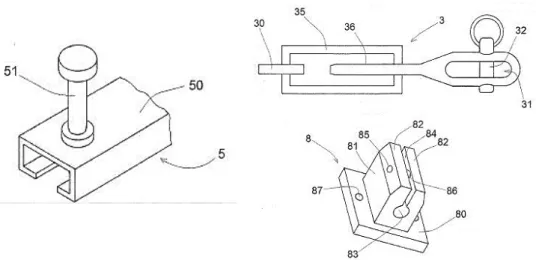
Figure 2.1. “Structural Member” 3d views: double T-section, C-section and the connection to the slab.
- Claims
The claims are the most important part of a patent. The goal of the claim is to point out and distinctly claim the subject matter of the invention. The patent claims will be reproduced. 1. System (100) for making building facades comprising:
- a pillar (1) intended to be connected to structural parts (W) of the building and to support panels (P) constituting the building façade; said pillar (1) comprising:
- a section (10; 210) intended to support said panels (P), said section being a pultruded profile made of synthetic resin reinforced with fiber glass and having cross-sectional dimensions lower than 100 mm x 100 mm, and
- at least one cable (2) connected to said profile and extending for the entire length of the profile, said cable (2) being obtained with a plurality of steel strands and being pretensioned, - connection means (M) to connect said profile to the structural parts (W) of the building, and - cable-fixing terminals (3) fixed at the ends of the cable (2) and connected to said structural parts (W) of the building or to said profile (10; 210) of the pillar.
2. The system (100) of claim 1, also comprising a plurality of cable-fixing clamps (8; 208; 308) fixed to said profile (10; 210) of the pillar to fix the cable (2) and one or more systems for pre-tensioning the cable (2).
3. The system (100) of claim 2, wherein the cable-fixing clamp (8; 208; 308) comprises opposite jaws (82; 280, 281) or a U-bolt consisting in a "U"-bent iron rod (380).
4. The system (100) of any one of the preceding claims, wherein each cable-fixing terminal (3) comprises tensioning means (35) to tension the cable (2) and said cable-fixing terminal (3) is hinged by means of a pin (32) to a bracket (7) adapted to be connected to the structural part (W) of the building or is hinged to a bolt (B) intended to be fixed to the profile (210) of the pillar.
5. The system (100) of any one of the preceding claims, also comprising a guide rail (5) integrated in said structural part (W) of the building, wherein said connection means (M) and/or said cable-fixing terminals (3) are connected to said guide rail (5) to adjust the position of said pillar (1).
20 6. The system (100) of any one of claims 2 to 5, wherein said profile (10; 210) of the pillar has a base (11) or central core (211) whereto said cable-fixing clamps (8; 208; 308) are fixed. 7. The system (100) of any one of the preceding claims, wherein said profile (10) of the pillar has a "U"-shaped cross-section and said profile (10) of the pillar comprises a base (11) and two wings (12) that protrude from the base defining a seat (13) wherein said cable (2) is disposed; wherein the wings (12) are faced towards the structural part (W) of the building and the base (11) is faced outwards in order to fix said panels (P) on the base (11) of the pillar profile.
8. The system (100) of claim 7, wherein said connection means (M) comprise brackets (4) made of profiles with an "L"-shaped cross-section; each bracket (4) comprising a first portion (40) intended to be connected to the structural part (W) of the building and a second portion (41) provided with a slot (42) wherein a bolt (43) slides, being fixed to a wing (12) of the pillar profile in order to adjust the distance of the pillar profile from the structural part (W) of the building.
9. The system (100) of any one of the preceding claims, wherein said profile (110) of the pillar has an "H"-shaped cross-section and said profile (210) of the pillar comprises a central core (211), a back wing (212) connected to the central core and a front wing (212) connected to the central core, in such manner to define two seats (213) wherein said cables (2) are disposed, wherein the back wing (212) is intended to be connected to the structural part (W) of the building and the front wing (212') is faced outwards to support said panels (P) of the façade.
10. The system (100) of claim 9, wherein said connection means (M) comprise angular brackets (4) directly connected to said back wing (212) and to said central core (211) of the pillar profile or connected to an intermediate bracket (9) connected to said back wing (212) of the pillar profile.
Figure 2.2. The mullion (1) is fixed to the loft (W) in order to support the façade panels (P); the mullion consists of a composite material profile (10) connected to strand (2).
21 Figure 2.3. The channel (5) is embedded in the loft; fork terminal (3) connected to strand (30); the clamp (8) permits in line the strand.
Figure 2.4. Cross-section of the mullion with the C profile (hypothesis 1); Cross-section of the mullion with the double T profile (hypothesis 2).
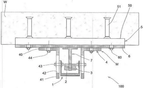
22 Figure 2.5. View from above, Cross-section of the façade system (hypothesis 1) embedded in the loft (W) through the Halfen channel (5) and brackets (M).
Figure 2.6. View from above, Cross-section of the façade system (hypothesis 2) embedded in the loft (W) through the Halfen channel (5) and brackets (M).
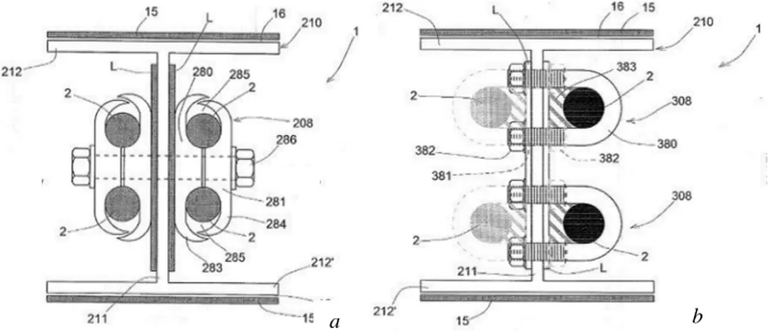
23 Figure 2.7. Cross-section of the double T profile (hypothesis 2) with four strands and different clamps a e b.
Figure 2.8. View from above, cross-section of the façade system (hypothesis 2) with four strands, embedded in the loft (W) through the Halfen channel (5) and brackets (M).
24 Figure 2.9. Cross-section, front view of the façade system; particular of the system with four strands anchorage to the loft (W) through the Halfen brackets.
2.3.
Product information
The Structural Member includes:
- GFRP profiles with different sections (C and double T) with areas less than 90x90 mm2; - steel laminates bonded to GFRP profiles with the objective of tightening the composite profiles and to facilitate the fixing of the panels;
- one or more pre-tended steel wires linked to the GFRP profile through several terminals, with the objective of containing deformations. The steel wires allow to reduce the member’s length of free inflection on every occasion. The ends of the steel wires are connected to the building’s structure through forks.
The Structural Member is linked to the building’s structure (slabs) through connection systems readily available on the market (corner guides Halfen, etc.).
2.4.
List of figures
Figure 2.1. Structural Member 3d views double T-section, C-section and the connection to the slab.
Figure 2.2. The mullion (1) is fixed to the loft (W) in order to support the façade panels (P); the mullion consists of a composite material profile (10) connects to strand (2). Figure 2.3. The channel (5) is embedded in the loft; fork terminal (3) connected to strand (30); the clamp (8) permits in line the strand.
25 Figure 2.4. Cross-section of the mullion with the C profile (hypothesis 1); Cross-section of the mullion with the double T profile (hypothesis 2).
Figure 2.5. View from above, cross-section of the façade system (hypothesis 1) embedded in the loft (W) through the Halfen channel (5) and brackets (M).
Figure 2.6. View from above, cross-section of the façade system (hypothesis 2) embedded in the loft (W) through the Halfen channel (5) and brackets (M).
Figure 2.7. Cross-section of the double T profile (hypothesis 2) with four strands and different clamps a e b.
Figure 2.8. View from above, cross-section of the façade system (hypothesis 2) with four strands, embedded in the loft (W) through the Halfen channel (5) and brackets (M).
Figure 2.9. Cross-section, front view of the façade system; particular of the system with four strands anchorage to the loft (W) through the Halfen brackets.
26
Chapter 3
On GFRP-steel hybrid bonding systems:
mechanical performances before and after
the ageing treatments.
In this work, the reliability of the Structural Member basic principle, i.e. the hybrid system of GFRP pultruded profiles bonded with steel laminates, is verified, with the objective of containing GFRPs deformations. The contents of this chapter will be published in a scientific international journal.
3.1.
Abstract
In this paper, the contribution in terms of stiffness increase by coupling steel laminates to GFRP pultruded profiles, through three epoxy adhesives, is investigated. The objective is to verify the applicability of this hybrid system in structural members for curtain walls. Different specimens types were employed in order to investigate on: the compatibility of the bonding system (shear tests on GFRP-steel single lap joints); the response to the local stresses of the bonding system (puncture tests on GFRP-steel squared tubular short profiles); the response to flexural stresses of the bonding system (three-point bending tests on GFRP-steel squared tubular long profiles). The effects of two environmental ageing, continuous condensation and UV radiations, were also analysed. The results demonstrated the compatibility of the bonding system and the stiffness increase of GFRP profiles when the steel reinforcements were applied. Analytical studies were comparable with those observed in the experimental tests, confirming the advantageous method of hybridization. With regard to artificial ageing, the continuous condensation demonstrated the worst effects on the specimens, while better results were registered after the UV radiations. The combinations of the two ageing conditions showed unexpectedly better results, with the enhancement of the mechanical performance of the joints.
27 Nomenclature
AF Adhesive failure L Steel plate positioned on the lower side of the GFRP profile
AGFRP Section area of the GFRP profile LFTF Light-Fiber-Tear Failure
ASTEEL Section area of the steel plate MF Mixed failure
At Application temperature NO No detachment
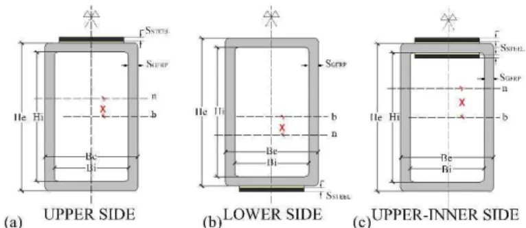
Be External dimension of the section area’s base P.D. Partial detachment
Bi Internal dimension of the section area’s base S Displacement
CF Cohesive failure St Service temperature
DIC T.D. Total detachment
DSC Differential scanning calorimeter T0 Un-aged conditions
EPX1 First epoxy adhesive Tcc Artificial ageing in climatic chamber
EPX2 Second epoxy adhesive Teig Extrapolated onset temperature
EPX3 Third epoxy adhesive Tefg Extrapolated end temperature
Et Young modulus in tension Tg Glass transition temperature
EGFRP Young modulus of GFRP profiles in tension Tuv Artificial ageing under UV rays
ESTEEL Young modulus of steel plates in tension U Steel plate positioned on the upper side of the GFRP profile
F Load carrying capacity U-I Steel plates positioned in the upper-inner side of GFRP profile
He External dimension of the section area’s height UV Ultraviolet radiations Hi Internal dimension of the section area’s height Wt Working time at 22 °C
IGFRP Moment of inertia of the GFRP profiles section area X The distance of the neutral axis from the barycentre ISTEEL Moment of inertia of the steel plate section area εt Tensile strain
kGFRP Stiffness of the GFRP sample σt Tensile strength
kSTEEL Stiffness of the steel plate σys Tensile yield strength
l Span length τ Average shear strength
K1GFRP-STEEL Stiffness of the GFRP-steel specimen: materials work together k2GFRP-STEEL Stiffness of the GFRP-steel specimen: materials do not collaborate
28
3.2.
Introduction
Despite the several advantages, it is well known in the literature that GFRP profiles present low elastic modulus with respect to steel (up to ten times lower) [1-4], preventing its use in the civil construction sector [5-7] especially when small profiles size is required, such as in curtain walls.
For this reason, it is necessary to develop suitable approaches to improve the stiffness of the GFRP pultruded material, and some authors demonstrate that coupling GFRP profiles with higher mechanical performances materials, especially steel, is an advantageous method [1,3]. However, to the authors knowledge, validated data for designers are still scarce and there has been little research on the comparison of different types of adhesives used for the joining of GFRP and steel profiles. Furthermore, the evaluation of the influence of environmental ageing was not presented, even if it is well known that bonding connections are adversely influenced by environmental conditions [8-10].
In the present work, an experimental campaign on the connection of GFRP pultruded profiles and steel laminates through three different epoxy adhesives is proposed. The objective is to investigate on three different aspects. (1) The first is the compatibility of the bonding system, through shear tests conducted on small-scale specimens (GFRP-steel single lap joints), also deepening on the effects of two environmental ageing. (2) The second is the response to the local stresses of the bonding system, through puncture resistance tests on full-scale specimens (GFRP-steel squared tubular short profiles) which simulate the local stress transmitted by the curtain panels bolted to the structural members; the effects of two environmental ageing is also carried out. (3) The third is the response to flexural stresses of the bonding system, through three-point bending tests on full-scale specimens (GFRP-steel squared tubular long profiles) which simulate the flexural stresses, undergoes by the whole structural members in curtain walls (i.e. the wind load).
3.3.
Methods
3.3.1. Phases
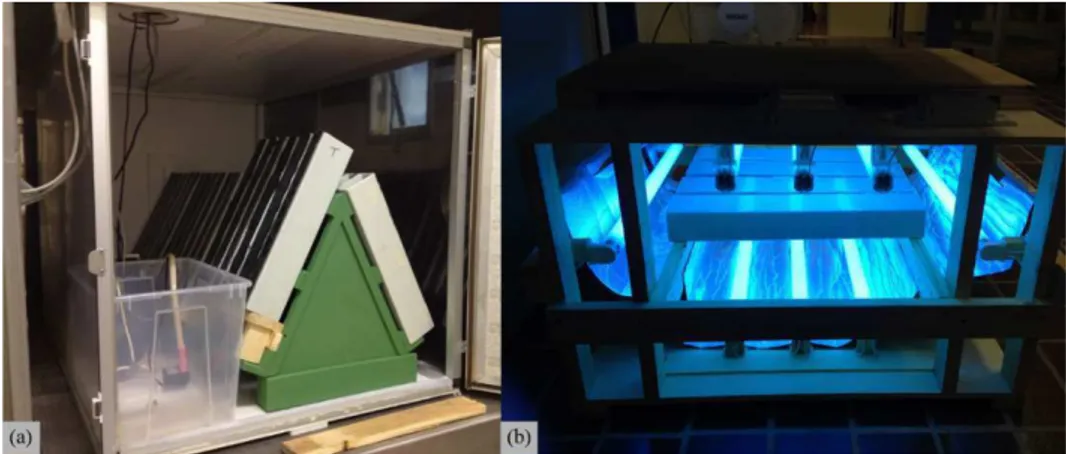
The research includes experimental and analytical studies, divided into the following phases: - Experimental tests were carried out to evaluate both the GFRP-steel compatibility and the steel contribution to enhancing the mechanical performances of the GFRP profiles. The experimental programme comprised: (i) material characterization tests, (ii) shear tests on adhesively bonded GFPR-steel single lap joints, (iii) puncture tests on GFPR-steel squared tubular short specimens and (iv) three-point bending tests on GFPR-steel squared tubular long specimens. The GFRP tubular specimens used in the two latter experimental tests (iii, iv) were adhesively joined to steel plates in three configurations, with the steel plates positioned in the upper, lower and “upper-inner” sides of the GFRP profiles (Fig.3.1), which are alternative positions of steel laminates with respect to the loading direction. Furthermore, the effect of two environmental ageing, namely continuous condensation and UV exposures, were analysed in steps (ii, iii) of the experimental programme.