POLITECNICO DI MILANO
Facoltà di Ingegneria Industriale
Dipartimento di Scienze e Tecnologie Aerospaziali Corso di Laurea Magistrale in Ingegneria Aeronautica
CHARACTERIZATION OF A
SELF-HEALING COMPOSITE:
MECHANICAL AND FUNCTIONAL PROPERTIES
Relatore: Dott. Ing. Antonio Mattia GRANDE
Tesi di Laurea di: Clara SIMÓN GARCÍA Matricola 894522 Anno Accademico 2018 – 2019
Contents
List of Figures ... v Sommario ... x Abstract ... xi Nomenclature ... xii Introduction ... 11 State of the Art ... 3
1.1 Smart Materials ... 3
1.2 Self-healing Materials ... 5
1.2.1 Basic Principles ... 5
1.2.2 Classification ... 7
1.3 Self-Healing Fibre-Reinforced Composites ... 11
1.3.1 Current Fibre-Reinforced Composites ... 11
1.3.2 Dynamic Covalent Chemistry ... 16
1.3.3 Dynamic Sulphur Chemistry ... 19
1.4 Self-healing Performance Evaluation... 34
2 Processing and Manufacturing ... 36
2.1 Introduction ... 36
2.2 Materials ... 37
2.2.1 Synthesis of Specimens ... 37
2.2.2 Dynamic Samples Manufacturing ... 41
2.3 Scanning Electron Microscopy (SEM) ... 43
3 Mechanical Characterization ... 51
3.1 Density Tests ... 51
3.2 Dynamic Mechanical Analysis (DMA) ... 53
4 Experimental Results ... 64
4.1 Density Tests ... 64
4.2 Dynamic Mechanical Analysis (DMA) ... 68
4.3 Differential Scanning Calorimetry (DSC) ... 76
5 Additional Functionalities ... 79 5.1 Mechanochromism ... 79 5.2 Reprocessability ... 93 5.3 Repairability ... 97 6 Conclusions ... 103 Acknowledgements ... 107 Bibliography ... 108
List of Figures
Figure 1.1.1. Active material: Piezoelectric Transducers ... 3
Figure 1.1.2. Active material: Shape Memory Polymer ... 4
Figure 1.1.3. Passive material: Fibre Optics ... 4
Figure 1.2.1. Damage management concept: traditional and self-healing materials [3] ... 5
Figure 1.2.2. Basic healing process [6] ... 6
Figure 1.2.3. Capsule-based self-healing composite [11] ... 8
Figure 1.2.4. Vascular self-healing approaches [3] ... 9
Figure 1.3.1. Epoxide group [21] ... 11
Figure 1.3.2. DGEBA resin [33] ... 11
Figure 1.3.3. Furan and maleimide bases polymers using reversible DA reactions [38] ... 16
Figure 1.3.4. CANs Classification [34] ... 17
Figure 1.3.5. Viscosity vs temperature within dissociative networks [3] ... 18
Figure 1.3.6. Recyclable ion gel using thiol/disulphide exchange mechanism [42]... 20
Figure 1.3.7. Representation of network healing through disulphide exchange reactions [27] ... 21
Figure 1.3.8. Schematic representation of the aromatic disulphide exchange reaction mechanisms [23] ... 22
Figure 1.3.9. Sequence of the healing event in a PUU elastomer [49] ... 23
Figure 1.3.10. Reprocessing of a PUU sample in the form of a cylinder (a) and from powder (b) [50] ... 24
Figure 1.3.11. Structure of the reference and dynamic epoxy networks ... 25
Figure 1.3.12. Normalized stress relaxation curves of dynamic epoxy network (a) and fitting of relaxation times (b) ... 26
Figure 1.3.13. Reprocessing experiments to characterize the dynamic epoxy network [50] ... 27
Figure 1.3.15. Synthetic procedure and chemical structure of the p-EPO and
o-EPO [25] ... 29
Figure 1.3.16. Hit and grounded p-EPO simples [25] ... 29
Figure 1.3.17. Composite manufacturing using dynamic epoxy prepregs (a) and reference epoxy prepregs (b) ... 30
Figure 1.3.18. Thermoprocessing of a cured composite laminate [50] ... 31
Figure 1.3.19. Samples of FRPs subjected to delamination (i) First ILSS (ii) Under heat and pressure (iii) Second ILSS test ... 32
Figure 1.3.20. Mechanical recycling of a CFRP [50] ... 32
Figure 1.3.21. Behaviour of FRPs under the effect of several chemical substances [50] ... 33
Figure 2.2.1. Memmert oven ... 38
Figure 2.2.2. Hot press ... 40
Figure 2.2.3. VELP Scientifica ARE magnetic stirrer... 42
Figure 2.2.4. Thermo Scientific Heraeus Oven ... 42
Figure 2.3.1. Bitech Europe grinding and polishing machine ... 43
Figure 2.3.2. Scanning electron microscope scheme [57] ... 44
Figure 2.3.3. Reference composite 1: fibre reinforcement detail ... 47
Figure 2.3.4. Dynamic composite: fibre reinforcement detail ... 47
Figure 2.3.5. Reference composite 1: SEM image 1... 48
Figure 2.3.6. Reference composite 1: SEM image 2... 48
Figure 2.3.7. Reference composite 2: SEM image 1... 49
Figure 2.3.8. Reference composite 2: SEM image 2... 49
Figure 2.3.9. Dynamic composite: SEM image 1 ... 50
Figure 2.3.10. Dynamic composite: SEM image 2 ... 50
Figure 3.1.1. Mohr Westphal balance ... 51
Figure 3.2.1. Relationship between the applied stress and the resulting strain [55]... 53
Figure 3.2.2. Material responses in DMA [54] ... 55
Figure 3.2.3. TA Instruments DMA 2980... 56
Figure 3.2.4. Dual cantilever clamp assembly ... 57
Figure 3.3.1. Representation of the advance of the cross-linking reaction [52] ... 60
Figure 3.3.2. DSC Scheme: 1) disk, 2) furnace, 3) lid, 4) differential thermocouple(s), 5) programmer and controller, S) crucible with sample
substance and R) crucible with reference sample substance [51] ... 61
Figure 3.3.3. TA Instruments DSC 2010 CE ... 61
Figure 3.3.4. TA Instrument Sample Encapsulating Press ... 62
Figure 4.1.1. Comparison of the void volume fraction calculated using the Archimedes principle (Mohr – Westphal balance) and SEM ... 66
Figure 4.2.1. Definition of DMA Tg in ASTM D7028 [62] ... 68
Figure 4.2.2. Example of DMA measure ... 69
Figure 4.2.3. Change in E when varying the fibre or void volume fraction ... 71
Figure 4.2.4. Reference composite 1: stress relaxation test ... 73
Figure 4.2.5. Reference composite 2: stress relaxation test ... 73
Figure 4.2.6. Dynamic composite: stress relaxation test ... 74
Figure 4.3.1. Example of DSC measure ... 76
Figure 5.1.1. Delamination scheme after impact in thick and thin laminates 79 Figure 5.1.2. Steel rod and transparent plexiglass tuve ... 80
Figure 5.1.3. Impact experiment setting ... 80
Figure 5.1.4. Impact tests scheme ... 81
Figure 5.1.5. Green zone characteristic area vs Impact height ... 83
Figure 5.1.6. Color intensity vs Impact height ... 84
Figure 5.1.7. Example of intensity colouring calculation ... 84
Figure 5.1.7. Sample after impact (room temperature): 0 hours ... 85
Figure 5.1.8. Samples after impact (room temperature): 2 hours ... 85
Figure 5.1.9. Sample after impact (room temperature): 24 hours... 86
Figure 5.1.10. Change in green coloration (impact time, left and after 4 days, right) on a frozen sample ... 87
Figure 5.1.11. SEM: delamination structure (1) ... 89
Figure 5.1.12. SEM: delamination structure (2) ... 89
Figure 5.1.13. SEM: delamination structure (3) ... 90
Figure 5.1.14. SEM: delamination structure (4) ... 90
Figure 5.1.15. SEM: delamination structure (5) ... 91
Figure 5.1.16. SEM: delamination structure (6) ... 91
Figure 5.2.1. Thermoforming process: lay-up, preheating, positioning, pressure application, demoulding and component attainment (from left to
right) [78] ... 93
Figure 5.2.2. Morphing wing with corrugated structure [80] ... 94
Figure 5.2.3. Mould 2D projection: geometry ... 94
Figure 5.2.4. Sample and mould placed within the hot press before pressure application ... 95
Figure 5.2.5. Sample after reshaping 1 ... 95
Figure 5.2.6. Sample after reshaping 2 ... 96
Figure 5.3.1. Hot press ... 98
Figure 5.3.2. Samples before (left) and after (right) the adhesion test ... 99
Figure 5.3.3. Instron 4302 tensile testing machine ... 100
Figure 5.3.4. Tensile test samples before (left) and after (right) the tests ... 100
List of Tables
Table 1.3.1. Comparison of properties for general thermoset matrices [32] . 12
Table 1.3.2. Advantages related to the use of fibre composites [31] ... 13
Table 1.3.3. Properties of the major types of glass fibres [31] ... 14
Table 1.3.4. Properties of the major types of carbon fibres [31] ... 14
Table 1.3.5. Thermal and mechanical properties of both reference and dynamic epoxy networks [40] ... 26
Table 2.3.1. Samples geometrical parameters ... 45
Table 4.1.1. Density measurements ... 64
Table 4.1.2. Density error measurements ... 65
Table 4.1.3. Void fraction obtained with density tests and SEM ... 66
Table 4.2.1. DMA Tg measurements ... 69
Table 4.2.2. Measured complex modulus and rule-of-mixture modulus ... 70
Table 4.2.3. Initial relaxation modulus in DMA stress relaxation mode ... 74
Table 4.3.1. DSC Tg measurements ... 77
Table 4.3.2. DSC and DMA Tg comparison ... 78
Table 4.3.3. DSC and DMA Tg comparison among the dynamic epoxy and the dynamic composite ... 78
Table 5.1.1. Sample’s impact behaviour ... 82
Table 5.1.2. Influence of temeprature on green coloration duration... 86
Table 5.1.3. Effect of impact test on the complex modulus ... 88
Sommario
Il presente elaborato si concentra sulla valutazione delle proprietà meccaniche e funzionali di un composito autorigenerante formato da una resina epossidica covalente dinamica e un rinforzo industriale in fibra di vetro a 0°/90°.
Nella tesi verranno brevemente presentati i progressi raggiunti in questo ambito, focalizzando l’attenzione sui reticoli reversibili polimerici caratterizzati da disolfuri aromatici. In primo luogo verranno esaminate le proprietà termomeccaniche del materiale composito dinamico attraverso lo studio comparativo con un materiale composito di riferimento. La seconda parte sarà dedicata alla valutazione di altre proprietà funzionali come il meccanocromismo, la rielaborazione, la riparabilità o la riciclabilità.
L'idea della tesi deriva da precedenti progetti realizzati al Politecnico di Milano che miravano a caratterizzare termomeccanicamente la resina epossidica dinamica. Grazie a questo lavoro verranno ampliate le potenziali applicazioni dei materiale multifunzionali, poiché prende in considerazione i materiali compositi, che rappresentano la rivoluzione tecnologica in corso nel settore aerospaziale.
Abstract
The present thesis focuses on assessing the mechanical and functional properties of a self-healing composite constituted by a dynamic covalent epoxy resin and a 0°/90° commercial glass fibre reinforcement.
Advances in the field are briefly explained, since different healing strategies are under research, but the focus is made on the investigation of reversible crosslinked composites based on aromatic disulphides. First, thermomechanical properties are assessed making a comparative study with a composite manufactured using commercial, industrial-tested materials and secondly additional functional properties are examined, such as mechanochromism, reprocessability, repairability or recyclability.
The idea of the dissertation stems from previous projects carried out at Politecnico di Milano which aim was characterizing the pure dynamic resin. Upscaling the project focusing on composites, which still are the ongoing technological revolution in aerospace manufacturing industry, potential applications of multifunctional materials are expanded.
Nomenclature
A Pre-exponential Arrhenius factor
AFM Atomic Force Microscope
AHEW Amine Hydrogen Equivalent Weight
BDSER Bis-disulphide bond Dynamic Epoxy Resin
CAN Covalent Adaptable Network
CFRP Carbon Fibre Reinforced Polymers
DA Diels Alder
DA-rDA Diels Alder/retro Diels Alder
DETDA Diethyltoluenediamine
DGEBA Diglycydil Ether of Bisphenol A
DCC Dynamic Covalent Chemistry
DMA Dynamic Mechanical Analysis
DMF Dimethylformamide
DSC Differential Scanning Calorimetry
E Young modulus
E’ Tensile storage modulus
E’’ Tensile loss modulus
E* Complex modulus
Ea Activation energy
EEW Epoxide Equivalent Weight
FRP Fibre Reinforced Polymers
FRPC Fibre Reinforced Polymer Composites
G’ Shear storage modulus
G’’ Shear loss modulus
GFRP Glass Fibre Reinforced Polymers
ILSS Interlaminar Shear Strength Test
K(T) Temperature dependent separable function
NDI Non-Destructive Inspections
PUU Poly(urea-urethane)
RTM Resin Transfer Moulding
SEM Scanning Electron Microscopy
Td Degradation temperature
Tg Glass transition temperature
Tv Freezing transition temperature
TGA Thermogravimetric analysis
TRL Technology Readiness Level
UV Ultraviolet
V Volume
Vv Void volume fraction
WLF Williams-Landel-Ferry
f Fibre volume fraction
o-EPO Ortho Epoxy
p-EPO Para Epoxy
phr Parts per 100 grams of epoxy resin
𝐭𝐚𝐧 𝜹 Loss factor
2-AFD 2-Aminophenyl disulphide
4-AFD 4-Aminophenyl disulphide
𝜶 Degree of cure 𝜺 Strain 𝜼 Efficiency 𝜼 Viscosity 𝝆 Density 𝝈 Stress 𝝎 Oscillation frequency 𝚫𝑯𝒄𝒖𝒓𝒆 Heat of cure
Introduction
Aerospace industry is well known for its role as technological driving force. Thus, high-performance materials have been developed. Composite materials evolution began in the 1960s motivated by the heavy weight of metallic components, the expansion of polymer industries and the discovery of high strength materials, such as glass fibres. Since then its implementation in the aerospace industry has grown exponentially.
Composite materials consist of a load carrier material embedded in a matrix, so that constituent materials properties are combined to exploit their synergies. They show greater strength characteristics, lower weight and higher fatigue and corrosion resistance than metallic alloys, so even if their manufacturing can be problematic, their advantages outweigh the disadvantages and new generation large aircraft, such as Airbus A350XWB and Boeing 787, are mainly designed using a primary composite structure.
Notwithstanding the above, composites still present major drawbacks that should be overcome to expand their application not only in the aerospace field, but also the automotive, construction and wind energy sectors. At present, composites manufacturing is very expensive and due to their nature, they cannot be reshaped, making their repair and recycling almost impossible. A solution is to entitle composites to repair themselves, just like biological systems, so that they can restore their mechanical properties. This kind of materials are known as self-healing materials.
The main objective of this thesis is to characterize mechanically a modified dynamic fibre reinforced polymer (FRP) comparing it with a reference glass fibre reinforced polymer (GFRP) and assessing several functionalities of the material, such as mechanochromism, thermoforming or adhesion to evaluate its repairability and
reprocessability capabilities, which will make it outperform the current composite materials.
This thesis will be presented in accordance to the following scheme:
1. State of the Art
Fundamentals and description of the main self-healing approaches and healing strategies, and self-healing materials additional functional properties.
2. Processing and Manufacturing
Description of the materials and manufacturing processes used within the development of the thesis. Observation techniques (SEM, mainly) are also included in this chapter, as a visual assessment is important to complete a material’s analysis. SEM is used throughout the thesis to evaluate the composite void volume fraction, fibres morphology and structural defects.
3. Mechanical Characterization
Explanation of the fundamentals of the used experimental techniques (namely DMA, DSC and Mohr – Westphal balance) for the material’s examination, as well as an overview of the experimental layout.
4. Experimental Results
Presentation and interpretation of the experimental results, comparing a reference composite with the thesis subject self-healing material.
5. Additional Functionalities
Evaluation of significant functional properties which the dynamic composite may show. Considering the research conducted at the IK4-CIDETEC Research Centre [50], experiments are realized to evaluate the material’s reprocessability and repairability.
6. Conclusions
Summary of the experimental results including the most remarkable differences, advantages and disadvantages of the assessed dynamic composite in comparison with the reference composite.
1 State of the Art
1.1 Smart Materials
Smart materials are materials which properties can be modified in a controlled way when an external stimulus is applied. These changes apply to their mechanical, thermal, optical or electromagnetic properties.
Inspired by living organisms, smart materials mirror the functionalities found in nature. If compared with the human body, it is observed that the host material must be endowed with sensors which process the received stimuli mimicking the nerves and actuators which adequately respond to the incoming signals imitating the muscles [1]. Furthermore, everything must be controlled by a data analysis system or brain which monitors the received signals, elaborates the acquired information and generates the proper reaction. Smartness describes the sensing and self-adaptability capacity.
Smart materials can be classified according to their working principle as active or passive materials. Active materials have the capacity to modify their properties under the application of an electric, thermal or magnetic field by transforming energy. Examples include piezoelectric materials (they generate a voltage when subjected to a mechanical stress and vice versa), shape memory alloys or polymers (these materials can be deformed and then returned to their original shape by heating) or magnetostrictive materials (they generate a magnetic field upon application of a stress).
Figure 1.1.2. Active material: Shape Memory Polymer
Passive materials cannot transduce energy but are able to change one of its properties under a stimulus. Within this group fibre optics (light properties change when a strain is implemented), pH-sensitive materials (they change their colour when acidity varies) or chromogenic systems (they change their colour in response to a stimulus) are included.
Figure 1.1.3. Passive material: Fibre Optics
The versatility of smart materials makes them suitable to solve actual engineering problems, in addition to providing the opportunity to design new generation products. Some of the possible applications of smart materials are vibration control, lifetime monitoring, self-healing, damping aeroelastic stability or active and passive controls. [2]
1.2 Self-healing Materials
1.2.1 Basic Principles
Within smart materials, this thesis focuses on self-healing materials. Following the biomimetic approach, self-healing materials are materials which can retrieve a functionality which has been diminished due to a damage.
Traditionally, the main goal of materials development was to improve them by enhancing their properties and optimizing their manufacturing process. Although materials with extraordinary properties have been developed, even smallest defects are not avoidable. That leads to the need of periodical inspections and repairs which are highly time-consuming and expensive. Fibre-reinforced polymer composites (FRPCs) are especially critical because they can suffer extreme internal damage from low velocity impacts without any external indication. Thus, non-destruction inspection techniques are needed to check for any possible defect. When damage is found, no repair technique can be used as standard since composites undergo several failure modes, such as fibre breakage, fibre pull out, matrix micro-cracking, interface debonding or delamination.
Developing self-healing materials therefore means a change in the material research philosophy: from damage prevention to healing. That means from avoiding crack creation to making the repair intrinsic to the material. Ideally self-healing materials could recover periodically their performance, extending their lifetime to an unlimited extent, hence enhancing their reliability. [4]
For the time being, self-healing technology has not reached the required ‘Technology Readiness Level’ (TRL) to be applied on a large scale, but the prospect is that these materials will be economically beneficial in the long run due to their higher reliability and durability [5]. Its application is anticipated in almost every industry. So far, it is being developed mainly in the aerospace, automotive, biomedical, civil and energy industries. Focusing on aerospace industry, self-healing materials offer huge advantages since reliability and safety are critical aspects. Furthermore, its implementation in spacecrafts is interesting since space maintenance is extremely difficult and expensive. [4]
Self-healing concepts can be applied to different material classes, such as metals, ceramics and polymers. These materials have different intrinsic properties, but the general healing process can be defined regardless of the material.
Whenever a damage is caused on the material, a crack can be generated. To repair the defect, a healing agent triggered either by the damage itself or an external stimulus is activated. The agent acts in the damaged area either by physical or chemical interactions assuring the crack planes reconnection. Once the healing action is performed, the agent action vanishes resulting in the restoration of the material mechanical properties.
Self-healing polymers are the most developed self-healing materials, since their structure makes them relatively easy to be modified. Metals and ceramics are characterized by the fact that atoms in the solid phase form rigid three-dimensional structures, but still are gaining attention due to their promising features.
1.2.2 Classification
Current self-healing polymers can be sorted in two main groups depending on the need of an external trigger to initiate the healing process: non-autonomic and autonomic. Non-autonomic self-healing materials require an external stimulus, like heat or light. By contrast, autonomic materials use the own damage as starter of the healing action. [7]
A second way of categorising self-healing composites is represented by the healing strategy: extrinsic and intrinsic healing. [8]
Extrinsic healing techniques consist in the use of a healing agent placed in the matrix as a separate phase. The reservoir breaks when damage occurs releasing the healing agent. The agent occasionally can self-react, but generally a catalyst is needed, which can be dispersed in the matrix or directly combined with the healing agent. The main approaches are the use of capsuled-based structures, liquid-filled hollow fibres or a mesoporous network. Consistent with the biological simile, capsules act like cells while hollow fibres and mesoporous networks mimic the vascular and circulation systems in animals. [9]
Capsule-based self-healing materials incorporate microcapsules in which the healing agent is embedded. When a crack appears and breaks a capsule, the healing agent moves towards the defect and repairs it. The first successful attempt was developed by White et al. [11] which included polymeric microcapsules filled with a cross-linkable liquid oligomer placed into a low viscosity epoxy matrix containing Grubbs catalyst, which yield a 75% recovery in toughness in fracture tests. Since
then this strategy has been extensively researched due to its ease of implementation, potentially even for mass production. Consequently, different combinations of healing agents and catalysts, capsules sizes and encapsulation techniques have been developed.
Figure 1.2.3. Capsule-based self-healing composite [11]
Changing the healing agent container, liquid-filled hollow fibres self-healing composites are obtained. Based on the previous research findings, Bond et al. [12] first showed an effective behaviour of this technique, obtaining a recovery of 97% in flexural strength and an easy way to trace the defects, since the used dye offered a proper damage visualization. The working principle is in line with the one of
microcapsules, but fibres offer the advantage of a better integration within an FRP and a larger potential recovery power, since the volume of healing agent is higher than the one contained within capsules. To obtain an effective healing action, it is necessary to optimize the number and spatial distribution of the hollow fibres. Extending the 1D vascular concept of liquid-filled hollow fibres, 2D and 3D networks have also been developed. [13] Its invasiveness must be minimized so that its effect does not undermine the polymer mechanical properties. Therefore, its structure and the healing agent characteristics, such as fluidity and stability, should be carefully selected.
Figure 1.2.4. Vascular self-healing approaches [3]
Although at present none of these strategies have been applied on large scale, it is likely that the integration of extrinsic healing systems to existing materials will be more straightforward than intrinsic approaches. Yet they present some inconveniences such as the potential chemical incompatibility between the healing agent and the composite, which is itself inhomogeneous, the scarce design window to introduce the healing agent in the structure and the fact that the healing action is
linked to the healing agent presence leads to singular healing events which magnitude is also limited by the healing agent quantity [5].
Intrinsic healing is based on the own healing capability of the matrix material. When subjected to an external stimulus or an internal damage, the material can repair itself through the reversibility of chemical or physical bonding in the matrix phase. No external agents are needed, so beforehand they have the advantage that multiple healing events can take place. The most significant strategies are based on reversible covalent bonds, thermoreversible physical interactions and supramolecular chemistry. [10]
Reversible covalent bonds are the basis of the self-healing behaviour of the fibre-reinforced composite used within the development of this thesis. Thus, a detailed explanation of the different investigated mechanisms is given down under the heading “Dynamic Covalent Chemistry”.
Self-healing behaviour based on reversible physical interactions involves the use of ionomeric polymers. Ionomers are polymer groups containing ionic species, such as metal salts, which form reversible clusters inducing mobility within the polymeric structure [14]. It has been extensively applied to study high velocity ballistic impacts [15], which could lead to its application in military aircraft, but also the general effect of cluster plasticisation on the self-healing behaviour [16].
Supramolecular chemistry works with interactions which are neither covalent nor physical, including π-π stacking, metal coordination and hydrogen bonding, being the latter the most researched approach. It seems to be an encouraging way to induce self-healing behaviour due to their low energy. Low molar mass monomers are held together by these interactions to obtain additional features, such as switchable environment-dependent properties or improved processing. The main challenge is finding the balance between having a reversible polymer and the association constant, since having a high reversibility can also be a synonym of smaller assemblies and poor mechanical properties. [17]
1.3 Self-Healing Fibre-Reinforced Composites
1.3.1 Current Fibre-Reinforced CompositesThermosetting materials are cross-linked polymers formed by an irreversible exothermic chemical reaction. The formed covalent polymer network is insoluble and mostly inert, which makes it almost impossible to recycle or reprocess once it has been formed. Their application cannot be at present substituted by thermoplastics, so it has become of critical importance to find a method to efficiently recycle this kind of polymers.
In the case of aerospace industry, the focus is made on obtaining reprocessable, repairable and recyclable fibre-reinforced thermoset composites using epoxy resins as matrix. Epoxy resins are thermosetting low-molecular-weight pre-polymers containing more than one epoxide group which properties depend on the type of epoxy resins and curation agents used during their manufacturing. The epoxide group is a three-membered ring formed by an oxygen and two carbons. Most of the commercially available epoxy resins are oligomers of diglycydil ether of bisphenol A (DGEBA) which react with a hardener [28]. DGEBA is extended due to its good mechanical properties and high glass transition temperature (𝑇𝑔).
Figure 1.3.1. Epoxide group [21]
Among the thermosetting resins, epoxy resins are of interest due to their magnificent chemical and mechanical properties, heat, electrical and water resistance, adhesion strength, low cure shrinkage, long shelf lives, availability and relatively cheap price. These outstanding characteristics have led to their extensive use as electronics encapsulation, sealants, coating, adhesives and of course matrices for fibre-reinforced composites. [20][21]
Thermosetting resins Property
Poly-ester Epoxy Phenolic
Bismale-imide
Poly-imide
Processability Good Good Fair Good Fair to
difficult Mechanical
properties Fair Excellent Fair Good Good
Heat resistance 82 ºC 93 ºC 176 ºC 176 ºC 260 – 315
ºC
Price range Low to
medium Low to medium Low to medium Low to medium High Delamination
resistance Fair Good Good Good Good
Toughness Poor Fair to
good Poor Fair Fair
Table 1.3.1. Comparison of properties for general thermoset matrices [32]
Although epoxy resins have been presented as outstanding materials, they still present some major drawbacks in their use as structural materials such as their inherent brittleness and rigidity, which make them prone to delamination and induce a poor impact resistance. To improve their physical properties, several paths can be followed. Within the aerospace industry, as well as toughening the matrix using a solid solution with a more ductile polymer, precipitating an elastomeric second phase or developing of interpenetrating polymer networks, fibres have been chosen as toughening agents. [31]
The ever-increasing use of high-performance fibre composites within aerospace applications is driven by the improvements in specific (property/density) strength and stiffness in comparison with metallic alloys. The main advantages are summarized in the following table.
Weight Saving
Higher range Lower fuel cost Increased payload Rising manoeuvrability
Lower Acquisition Cost
Lower manufacturing cost Better “fly-to-buy” ratio
Lower assembly costs
Higher Performance
Improved aerodynamics Good aeroelastic properties Higher temperature capability
Better damage tolerance Lower detectability
Lower Maintenance Cost
Better fatigue and corrosion resistance Better mechanical damage resistance
Table 1.3.2. Advantages related to the use of fibre composites [31]
Reinforcement fibres are generally circular cross section tubes made of low atomic number elements, including carbon, boron, aluminium and silicon, which can be formed into stiff, low density materials. These materials are manufactured in the form of fibres due to their strong directional interatomic bonds. This entails that
they cannot relieve stress concentration by plastic flow and are notably weakened by defects, especially when they are superficial. According to Weibull statistics, the probability of a defect existing per unit length is an inverse function of the material volume; hence as a fibre presents a low volume, it is less susceptible to damage. [31] Within this thesis the focus is made on glass and carbon fibres, as their use is widely extended in the aerospace industry due to their high strength-to-weight and stiffness-to-weight ratios. In Table 1.3.3 and Table 1.3.4 the properties of the main commercially glass and carbon fibres are shown.
Glass Fibres
Property E-Electrical S-High Strength
Specific gravity 2,6 2,5
Tensile modulus (GPa) 73 87
Tensile strength (MPa) 3445 4890
Ultimate strain (%) 3,5 4,5
Thermal expansion (x10-6 mm-1K-1) 5 5,6
Table 1.3.3. Properties of the major types of glass fibres [31]
Carbon Fibres
Property HM Type I HS Type II IM Type III
Specific gravity 1,9 1,8 1,8
Tensile modulus (GPa) 276 – 380 228 – 241 296
Tensile strength (MPa) 2415 –
2555
3105 –
4555 4800
Ultimate strain (%) 0,6 – 0,7 1,3 – 1,8 2,0
Thermal expansion (x10-6 mm-1K-1) - 0,7 - 0,5 N/A
Thermal conductivity (Wm-1K-1) 64 – 70 8,1 – 9,3 N/A
Electrical resistivity (µΩm) 9 – 10 15 – 18 N/A
Glass fibre-reinforced composites are used due to the simplicity and low cost of glass fibres manufacturing from the molten state, their strength and their chemical inertness, which helps corrosion inhibition. In the aerospace industry glass fibre composites are used in the secondary aircraft structure, where no heavy loads are applied such as window surrounds, storage compartments, wing fairings and wing fixed trailing edge panels. [32]
Carbon fibre-reinforced polymers have the highest specific modulus and specific strength of all reinforcing fibre materials, so their application is highly extended in the aerospace industry. Carbon fibres can retain these properties even at high temperatures and at room temperature they do not chemically react with most of solvents, acids or bases. [54]
Present solutions for the disposal of fibre-reinforced polymers are heavily polluting, highly energy consuming and generate a significant material waste. Landfill is the current cheapest option, but also the least preferred option under the European Union’s Waste Framework Directive, which means that it is prone to be prohibited at least on European territory as environmental legislation is becoming more and more restrictive. Other recycling techniques include mechanical processes such as grinding, pyrolysis and solvolysis. Pyrolysis is commonly used in the chemical industry, so its extension as an industrial scale process was the most straightforward. During the process, fibres are contaminated and degraded at high temperature, so chemical treatments have been thought as a reasonable alternative to pyrolysis. Solvolysis techniques can be extensively tuned using different solvents, temperature and pressure levels, and catalysts depending on the material, but still they are not commercially exploited. [22]
1.3.2 Dynamic Covalent Chemistry
Dynamic Covalent Chemistry (DCC) consists in extending the dynamic features found in supramolecular chemistry to molecular chemistry using reversible covalent bonds. DCC covers dynamers, covalent adaptable networks (CANs) and vitrimers.
The first step in the development of dynamic components are dynamers, which are
“constitutional dynamic polymers of either supramolecular or molecular nature whose monomeric components are linked through reversible connections, which can be either non-covalent interaction or reversible covalent bonds”, according to Skene and Lehn
[29]. They can respond to physical and chemical stimuli by establishing reversible networks.
The most studied dynamic covalent reaction within the self-healing materials field is the Diels-Alder/retro-Diels-Alder (DA-rDA) reaction for cross-linking linear polymers. The reversible bond was first reported in the late 1960s, but first implemented by Chen et al. [36] using furan-maleimide polymers. It has also being used to create a thermally activated self-healing carbon fibre composite including a bis-maleimide tetrafuran which presented almost a 100% strength recovery [7] [37].
CANs refer to the networks in which a cross-linked structure is present due to the number and topology of reversible covalent bonds and can be modified under an applied stimulus. The network does not suffer any degradation; hence, it maintains the initial bond density while the material responds to the stimulus. CANs can be manufactured from monomers connected through reversible linkages, as part of the fabrication process or by using proper functional groups [30].
CANs can be classified according to their exchange mechanism: dissociative and associative networks. Both mechanisms are schemed in Figure 1.3.4.
Figure 1.3.4. CANs Classification [34]
In dissociative networks, bonds are first broken and then reformed, which make them momentarily lose their integrity. The most common dissociative networks are again based on DA reactions between furans and maleimides. Cross-linking becomes a reversible reaction upon heating leading to a fast reorganization of the network and a significant viscosity drop. Upon cooling, the network recovers its stiffness and insolubility properties, allowing thermal reprocessing and healing of the material. [34]
Figure 1.3.5. Viscosity vs temperature within dissociative networks [3]
Associate networks main characteristic is their fixed cross-link density; hence, they are both dynamic and permanent, since a bond is only broken after a new covalent bond has been formed. Several networks were reported during the first decade of the 21st century, but it was not until Leibler et al. [39] found in 2011 a network
formed by a transesterification catalyst and an epoxy/acid or epoxy/anhydride that these polymers showed relevant functionalities. These networks have a gradual viscosity reduction upon heating, such as vitreous silica. Honouring this feature, these materials were named vitrimers.
Vitrimers behaviour is mainly dependent on temperature and their covalent bond structure. At high temperatures, viscosity is driven by chemical change reactions; thus, viscosity decreases following the Arrhenius law, unlike thermoplastics and dissociative CANs which are ruled by the Williams-Landel-Ferry model (WLF). Until degradation temperature range is reached, vitrimers maintain their integrity, that meaning that they do not dissolve in chemically inert solvents.
Vitrimers viscoelastic behaviour can be defined using two transition temperatures: glass-transition temperature (𝑇𝑔) and freezing transition temperature (𝑇𝑣).
𝑇𝑔 is one of most important thermophysical properties of polymers and its meaning is equivalent to the melting point of non-amorphous materials. It divides the glassy, hard and brittle, and the rubbery and soft states and therefore is correlated to molecular motion.
𝑇𝑣 depends on the cross-linking exchange reactions and marks the transition
between viscoelastic solid and viscoelastic liquid, as the network begins to flow (the timescale of bond exchange reactions is lower than the timescale of material formation). It is hereby established that the temperature coincides with the point in which a viscosity of 1012 Pa·s is reached.
Both temperature values need to be considered when designing the polymer, so several parameters are used to control them, such as exchange reaction kinetics, intrinsic rigidity of monomers or cross-linking density. [35]
1.3.3 Dynamic Sulphur Chemistry
Among the chemical bonds prone to be used to manufacture dynamic polymers, sulphur-containing compounds have been extensively researched, especially networks including thiol/disulphide exchange and disulphide exchange. Disulphide bonds are weaker than carbon bonds, facilitating the mechanical scission [45]. Thiol/disulphide exchange mechanism is based on the nucleophilic displacement of a thiolate anion from the disulphide when attacked by another thiolate anion. It is highly influenced by changes in pH, which is an advantage when using a pH trigger as catalyst, but also a disadvantage when polymers are subjected to aerial oxidation or work in acidic conditions, as no enough reactive thiolates are present, weakening the network dynamic properties. [26]
One successful investigation was presented by Wei et al. [42]. Due to the mild transformation conditions of the thiol/disulphide a reversible ion gel with high
toughness, high conductivity and recyclability was produced. The gel could be six times reshaped under relative low values of temperature (60 °C) and pressure (0.04 MPa) with no relevant performance loss and without the need of an external agent.
Figure 1.3.6. Recyclable ion gel using thiol/disulphide exchange mechanism [42]
Disulphides respond at room temperature, as a reasonable level of bond strength is achieved. It usually needs to be triggered by chemicals, heat or UV light, but some autonomous examples have also been reported. Disulphide chemistry owes its versatility to the reversibility of the S-S bond cleavage which generates sulphenyl radicals.
Being recyclability one of the main reasons for the use of dynamic covalently bound materials, Johnson et al. [43] presented a disulphide-containing epoxy which degradation kinetics can be controlled by temperature, concentration of disulphide groups and monomer stoichiometry. This study also proved that disulphide-containing epoxy thermosets are stable under severe conditions.
Takahashi et al. [41] reported the development of degradable epoxy resins using disulphide linkages synthetized from bis(4-glycidyloxyphenyl) disulphide and several diamines. While mechanical properties were comparable to the ones of the reference resin, the dynamic epoxy resins showed the ability to fragment rapidly, allowing the resin recyclability.
Also, vitrimer materials containing disulphide bonds have been researched by Zhou
et al. [46], which synthesized BDSER by the reaction of a difunctional epoxy
monomer with 4,4’-disulfanediyldianiline (4-AFD). The introduction of more disulphide bonds was expected to increase the repair capacity of the matrix. The material showed excellent mechanical and thermodynamic materials, as well as good reprocessability, self-healing, degradability, low activation energy and fast relaxation times.
Figure 1.3.7. Representation of network healing through disulphide exchange reactions [27]
To improve the bond interchange rates and lower the bond strength, disulphide bonds can be replaced with tetrasulphides, as the stability of the S-S bridge is reduced when a higher number of sulphur atoms is present. Abdolah Zadeh et al. [47] developed a dual organic-inorganic crosslinked network by sol-gel process. Tetrasulphide content revealed to have an important effect on healing temperature and polymer structure when repairing a crack. Dynamic exchanges induce the flow of the crosslinked network while irreversible linkages keep the mechanical integrity of the polymer. The industrial implementation of this innovative technology depends on the long-term performance of the healed material, so as well as the dependence of the material on the dynamic covalent bonds, the effect of curing time was studied [44]. It was found that increasing the curing time improved the material
stability and mechanical properties, but was not related to the healing efficiency, as the number of available S-S bonds does not change.
Within disulphide exchange mechanisms, the most promising is the aromatic disulphide exchange. Little was known regarding the reaction mechanism and electronic structure allowing the dynamic network behaviour, so a theoretical approach was developed by Matxain et al. [23]. The scope of this study was achieving a better understanding of the reaction at molecular level, so that self-healing behaviour implementation could be improved. Several compounds where derived from diphenyl disulphide to analyse the effects of substitution on the chemistry of the process. The research concluded that the chemical structure is significant to improve self-healing materials properties and deduced that the main reaction mechanism of the aromatic disulphide exchange is a radical mediated mechanism.
Self-healing behaviour depends on the disulphide cleavage, hydrogen bond between polymer chains and the capability to overcome the reaction barrier at room temperature. Bond dissociation energy is lowered when para-substituting phenyl groups with ring-activating moieties, making the aromatic ring more stable and promoting bond division. Hydrogen bonding keeps the disulphide chains close, that meaning that they are fundamental for the polymer structure. [23][45]
Aromatic disulphide exchange has been used to modify polyurethanes, poly(urea-urethanes), polyimides and epoxy resins.
Rekondo et al. [49] reported self-healing poly(urea-urethane) elastomers with 97% healing efficiency in tensile strength tests at room temperature after being cut in half with a razor blade, just by contact between the halves. The significant healing efficiency has been attributed to the aromatic disulphide content, as well as the presence of two urea groups, capable of forming a quadruple hydrogen bond. Its easy preparation from commercially available materials makes the industrial use of these kind of elastomers promising in the short run.
Figure 1.3.9. Sequence of the healing event in a PUU elastomer [49]
Moreover, this research group [50] demonstrated that poly(urea-urethane) elastomers based on aromatic disulphides can also be manufactured for reprocessing by applying temperature and pressure on a mould. The obtained polymer shows the same mechanical properties as the pristine sample. Reprocessing was achieved using both a cylinder sample and powder, which offers the advantage of using the cured resin directly as starting material. Although mechanical tests show that aromatic disulphides can rearrange the material at room temperature, it is necessary to carry out rheology experiments to study the stress
relaxation. Rheology tests showed that the polymer needs to be treated above 100 °C to completely relax.
Figure 1.3.10. Reprocessing of a PUU sample in the form of a cylinder (a) and from powder (b) [50]
Grande et al. [24] deepened in the study of poly(urea-urethanes) examining the function of the hydrogen bonds and disulphide content; thus, the polymer structure. Different samples were prepared maintaining the number of disulphide linkages but changing the crosslinking density. The change in the network was proved to be directly correlated to the mechanical properties and healing efficiency.
Also based on the reversible exchange of aromatic disulphides, Ruiz de Luzuriaga et
al. [40] have developed an epoxy vitrimer system which shows the following
interesting features: synthesis from available starting materials, easy reprocessability, repairability and recyclability. To analyse the advantageous properties of the new system, a comparison between DGEBA with 4-aminophenyl disulphide (4-AFD) as dynamic hardener and DGEBA with diethyltoluenediamine
(DETDA) as reference hardener was made. Mixing of the resin prepolymer and the corresponding hardener was made at 60 – 80 °C followed by a curing process at higher temperatures.
Figure 1.3.11. Structure of the reference and dynamic epoxy networks
Thermomechanical analysis was carried out to determine the 𝑇𝑔, inferior
degradation temperature (𝑇𝑑), storage modulus (E’), stress and strain at break.
𝑇𝑔 values are comparable using both differential scanning calorimetry (DSC) and dynamic mechanical analysis (DMA). Thermogravimetric analysis (TGA) showed a difference in thermal stability, as the dynamic network has a lower 𝑇𝑑, which is likely to be linked to the presence of the disulphide bond. E’ values are analogous in both networks regardless the test temperature. Tensile tests revealed a similar behaviour of the thermosets, which means that mechanical properties are not affected by the dynamic hardener below 𝑇𝑔.
Tg(DSC) [°C] Tg(DMA) [°C] Td [°C] E’ (25 °C) [GPa] E’ (150 °C) [GPa] Stress [MPa] Strain [%] Reference network 127 130 350 2,5 20 81 7,3 Dynamic network 130 130 300 2,6 20 88 7,1
Table 1.3.5. Thermal and mechanical properties of both reference and dynamic epoxy networks [40]
Following the usual thermomechanical tests, dynamic properties were assessed. First, stress relaxation was considered. The time and temperature dependent relaxation modulus of the dynamic epoxy resin were tested by DMA. The obtained results showed that complete relaxation and flow occur when reaching a temperature higher than 𝑇𝑔. Relaxation times were found using the Maxwell’s model for viscoelastic fluids and ranged from 3 hours at 130 °C to 20 seconds at 200 °C. To prove that the dynamic epoxy network presents a vitrimer behaviour, it is necessary to determine 𝑇𝑣. Fitting the relaxation time as a function dependent on temperature following the Arrhenius’s law, 𝑇𝑣 was extrapolated.
Figure 1.3.12. Normalized stress relaxation curves of dynamic epoxy network (a) and fitting of relaxation times (b)
After obtaining the reference vitrimer temperatures, reprocessability, repairability and recyclability of the material was tested. Three different experiments were carried out.
The first one consisted in processing two samples, one of each epoxy resin, in a hot press at 200 °C and 100 bar for 5 minutes. The reference epoxy led to a powder state material, while the dynamic epoxy created a new sample in the form of a film. Its mechanical properties were identical to the ones showed by the original sample. The second test involved the ability of the dynamic network to self-repair. A small superficial scratch was made on two samples and heat and pressure were applied. The reference epoxy showed no change, but the dynamic epoxy could be repaired when the temperature reached a value above 𝑇𝑔.
The final test was planned to evaluate the material recyclability. Two resin samples were grinded and then compacted into a mould in which heat and pressure were applied. The reference epoxy resin could not be recovered, but the dynamic sample showed perfect visual appearance and its mechanical properties were like the ones of the pristine sample.
Following the work of Ruiz de Luzuriaga et al. [40], Paolillo [48] completely characterized the behaviour of an epoxy resin at Politecnico di Milano, which will be used within the development of this thesis. DGEBA and 4-AFD will be used as resin prepolymer and hardener of the dynamic epoxy and DGEBA with 4,4’-ethylenedianiline will constitute the reference epoxy to manufacture both the dynamic and reference composites which will be analysed.
Figure 1.3.14. 4-AFD (left) and 4,4’-ethylenedianiline (right) [48]
Few examples of FRPs containing reversible polymer networks have been yet researched. The dynamic behaviour is usually induced into the polymer matrix using a hardener which generally does not generate any additional features within the polymer. Again Ruiz de Luzuriaga et al. [25] reported that the previously described 4-AFD, used as dynamic hardener for the generation of dynamic epoxy networks or vitrimers, can induce a mechanochromic functionality within the polymeric network. This group developed a dynamic epoxy resin based on reversible aromatic disulphide crosslinks (p-EPO), which showed a green coloration when machined or hit which disappeared spontaneously after several hours. To understand which chemical species are inducing this functionality and its time dependency an additional epoxy network was studied (o-EPO) including 2-AFD as hardener.
p-EPO showed green coloration when hit and grounded to power, that meaning, when broken. The colour disappeared gradually after 24 hours at room temperature. To analyse the temperature dependency a sample was placed into an oven at 150 °C and another in a freezer at -20 °C. The oven sample lost its green
coloration within 30 seconds, while the frozen one maintained the colour for days. A suitable explanation is the direct dependence between temperature and chain mobility.
Figure 1.3.15. Synthetic procedure and chemical structure of the p-EPO and o-EPO [25]
o-EPO samples were subjected to the same mechanical tests, but no green coloration appeared. 4-AFD and 2-AFD are isomers which only difference is the relative position of the disulphide and the amino substituents, so its different behaviour seemed surprising, but highlighted the important of the chemical structure.
Mechanochromism is a significant functionality since it can be used to detect stress, strain and deformation, as well as damage, which is especially useful in the evaluation of FRPs. [26]
As well as FRPs monitoring, composites manufacturing processes can highly benefit when introducing the previously described dynamic epoxies. Currently, the epoxy matrix is partially cured before the lay-up of the composite, so that fibres are maintained within the matrix and enough functional groups are present to complete the curing of the thermoset. Since the matrix has not reached its final state, it has a limited shelf-life (in which it must be refrigerated) and out-life before it loses its ability to self-adhere or adhere to the tool. If dynamic networks were introduced, these disadvantages could be overcome, as this group reported that a compacted multilayer composite was obtained when laying up and hot pressing eight single enduring prepreg sheets using the dynamic epoxy, while no attachment was achieved when using regular prepregs.
Extending the reshaping capability of the dynamic epoxy, thermoforming can be introduced, which is the deformation of the composite even after curing. Actual techniques to manufacture 3D composites are extremely complex or even impossible when using conventional epoxy composites, while thermoforming offers the possibility to produce 3D composites from 2D laminates. Thermoforming was analysed using a sheet of multi-layered dynamic CFRP using resin transfer moulding (RTM) which was then placed in a preheated zig-zag mould and processed in a hot press. After cooling, the desired shape was obtained. When using a regular epoxy, the used specimen could not withstand the process.
Figure 1.3.18. Thermoprocessing of a cured composite laminate [50]
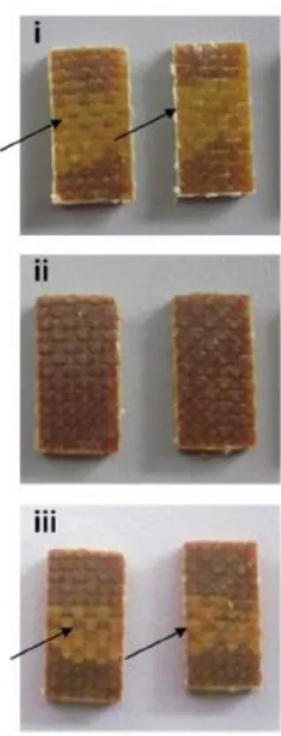
Repairing composites requires at present time special techniques and skilled workers, therefore more automated maintenance methods need to be created. Within the most common failures in multilayer composites, delamination is found. This problem could be solved by the self-adhesion capability of dynamic epoxy resins. Several samples where cut from a CFRP sheet (ISO 14130) manufactured from prepregs and then delamination was induced. Then heat and pressure were applied, and delamination disappeared. Subjecting the samples to interlaminar shear strength tests (ILSS), it was shown that mechanical properties were approximately recovered.
Figure 1.3.19. Samples of FRPs subjected to delamination (i) First ILSS (ii) Under heat and pressure (iii) Second ILSS test
Finally, both mechanical and chemical recycling have been assessed. Mechanical recycling was achieved by grinding the CFRP and compressing the obtained powder in a mould. As reinforcement fibres lose its form, mechanical performance cannot be as high as the one obtained with the original material, so it could not be used as structural material.
Figure 1.3.20. Mechanical recycling of a CFRP [50]
Dynamic epoxy showed a good resistance to several chemical substances, but the reversible nature of the crosslinks allows the network to be dissolved in the presence of a thiol, following the thiol/disulphide exchange mechanism. Introducing
a sample in a solution of 2-mercaptoethanol in DMF, after 24 hours under vacuum in an oven at 100 °C, the reinforcement fibres could be recovered undamaged after matrix dissolution.
1.4 Self-healing Performance Evaluation
Self-healing processes include both structure and functionality restoration. The first step in assessing self-healing performance consists on the observation of the structure recovery. Some of the techniques applied for the optical characterization involve the use of optimal microscope, laser microscope, scanning electron microscope (SEM) and atomic force microscope (AFM). [18]
With a view to evaluate quantitatively the quality of healing, the healing efficiency, denominated η, is used. It is defined as the ratio of a material property of the healed sample to that of the virgin sample.
𝜂 =𝑃ℎ𝑒𝑎𝑙𝑒𝑑 𝑃𝑣𝑖𝑟𝑔𝑖𝑛
· 100%
Despite being a quantitative parameter, its direct interpretation may not be accurate. Some polymers can show a very fragile behaviour, while the ones used in real applications have stronger matrices. If they are used indistinctly as reference materials, the results can significantly vary. Furthermore, the effect of the healing additives on the virgin polymer can help or suppress the healing efficiency and it changes depending on the applied loadings. Alternate definitions can then be used to normalise the healing material properties comparing the properties of the healed material with the ones of the original material without added healing components.
𝜂 = 𝑃ℎ𝑒𝑎𝑙𝑒𝑑
𝑃𝑛𝑜ℎ𝑒𝑎𝑙𝑖𝑛𝑔· 100%
Another factor that can considerably affect the healing efficiency is the extent of the damage. When using samples that have catastrophically failed, healing effect measurements are more reliable, but it does not respond to the target application of self-healing materials, which is restoring the original material properties when partial damage is present.
As stated before, FRPs suffer several failure modes, so in order to assess the healing effect, several different damage methods should be studied. Currently no standard processes have been described, but most often mechanical properties are primarily tested using tensile, compression or bending test protocols. Other experimentations which have already been carried out include impact, scratching, hammering or indentation tests. Depending on the test, several healing efficiency definitions can be applied using the appropriate property. [19]
2 Processing and Manufacturing
2.1 Introduction
Manufacturing is a key factor in the composites design process, since it heavily influences the properties and cost of the material. Preparation for a composite manufacturing should proceed in coordination with the early design concepts and includes the selection of materials, composites quality assurance, development of a manufacturing plan, setting of the material requirements and tools, and production process development.
Figure 2.1.1 describes the generic phases of a laminate thermosetting composite manufacturing process.
Figure 2.1.1. Flow chart of composite laminate part fabrication [32]
Within this thesis only small samples with a relatively simple geometry will be manufactured, so this chapter focuses on the used materials to produce both the self-healing material and reference samplings, the explanation of the different implemented manufacturing strategies and the observation of the produced specimens using Scanning Electron Microscopy (SEM) to determine which manufacturing process is more suitable to fit the material required criteria.
2.2 Materials
HEXFORCE ® - HEXCEL ® E glass fabric, nominal weight 290 g/m2, thickness 0,23
mm, 7 yarn/cm warp and 7 picks/cm weft, SX8 EVO A epoxy resin and SX8 EVO B hardener purchased from Mike Compositi were used to manufacture the reference samples. [68][69]
D.E.R. ™ 332 diglycidyl ether of bisphenol A (DGEBA) and 4-aminophenyl disulphide (4-AFD, 98%) were used for manufacturing the dynamic samples and were purchased from Sigma-Aldrich. Glass fibre reinforcement is maintained in the dynamic samples production.
2.2.1 Synthesis of Specimens
2.2.1.1 First procedure: Vacuum Bag + Heating
The first sample manufactured within this thesis consisted on a 10 x 10 cm four-layer glass fibre reinforced composite using the reference epoxy resin and hardener. The objective was achieving a composite with 50% fibre reinforcement, so the first step before beginning with the lay-up was weighting the fibre fabric so to introduce a proper amount of resin. The fibre reinforcement weight was 12,14 g, so to assure a proper fibre content, 15 g of matrix were used, since part of the resin is lost during curing. According to the resin properties, to have a complete cross-linking reaction, the ratio of epoxy resin and hardener is 100:30, so within 15 g, theoretically, 11,5 g of resin and 3,5 g of hardener were needed. In the actual sample 11,48 g of resin and 3,52 g of hardener were introduced.
Once the epoxy resin and the hardener were mixed, fibre fabric and matrix were manually laid up using a regular plastic spatula so that resin is homogeneously distributed. As it is a manual process, it is difficult to avoid the generation of void within the material, so a grid is placed above to facilitate the extraction of the
retained air. After the grid, the composite is covered by a release peel ply which enables the separation of the composite from the bleeder, which is the next layer. The bleeder holds the excess resin from the composite. The vacuum bagging film in which all the mentioned materials are placed is then sealed using a rubber and connected to the vacuum pump via a vacuum connector.
Resin data sheet suggested 20 h at room temperature and 5 h at 70 °C for complete curing, but in this trial the sample was directly introduced 5 h in the oven maintaining vacuum [53]. After 1 h in the Memmert oven, the vacuum bag was checked to see if the sealing was properly working or if the bag was partially opened. The rubber was not perfectly hermetically closed, so silicone adhesive was introduced in the vacuum bag critical points.
Figure 2.2.1. Memmert oven
The obtained sample weighted 16,36 g, so to determine the volume fraction of fibre reinforcement present within the specimen, rule of mixtures is applied,
𝑓 = 𝑉𝑓 𝑉𝑓+ 𝑉𝑚
where 𝑓 is the fibre volume fraction and 𝑉𝑓 and 𝑉𝑚, the volume of both the present phases, fibre reinforcement and matrix. The achieved fibre volume fraction was 53,54%, which is above the target value. Reformulating the rule of mixtures, theoretical density can be calculated. Rule of mixtures is generally applied in materials science, especially in the composites field, since it theoretically delimits the values of properties such as the elastic modulus or the density. It consists on a volume-weighted mean which considers both the properties of the matrix and the fibres. In the present case, the rule can be described as
𝜌𝑐 = 𝑓𝜌𝑓+ (1 − 𝑓)𝜌𝑚
The resultant value will be later compared to the measured density value, so to assess the presence of voids within the material.
2.2.1.2 Second Procedure: Hot Press
Before starting the manufacturing of the dynamic samples, a second manufacturing technique was tried to attempt to reduce the defects present in the specimen. The first step in this manufacturing process is analogous to the one followed in the first trial: manual lay-up. In order to measure and optimize the quantity of needed resin, 15 g of epoxy and 4,5 g of hardener were mixed to ensure that enough resin was available for the lay-up. 11,15 g of resin were needed for the lay-up, that meaning that using this method the fibre-matrix weight ratio, considering that 10,83 g of fibre were used, is of 97,13%. Minimization of resin utilization is important not to waste material, but in the case of the dynamic epoxy is crucial, as its cost is considerably higher than the one of a regular polymer. Cost optimization falls
beyond the scope of this thesis, but since it is one of the factors limiting the current feasibility of self-healing materials, it should be accounted.
The composite was laid up onto a vacuum bag film and covered by Teflon. It was then introduced within another vacuum bag film to create a double layer coverage. After that, it was placed in a hot press for 20 h at room temperature and 5h at 70 °C. The pressure within the press is controlled by a built-in barometer which scale is 2 bar, so a precise control is not provided. The real pressure ranges from 5 to 6 bar. After its curing, the specimen weighted 13,66 g, which lead to a theoretical volume fibre fraction of 60,52%, which constitutes an improvement with regard to the first trial.
2.2.2 Dynamic Samples Manufacturing
When manufacturing the reference samples, the suggested resin hardener ratio was used, while in order to produce dynamic samples, no supplier recommendation is available. In order to achieve the optimum performance from a resin/hardener system, it is necessary to use an appropriate stoichiometric mix ratio. When using functional epoxide/reactive curing agents, it is desirable to make react resin and hardener at approximately stoichiometric quantities. [67] To calculate the stoichiometric quantity of amine in weight parts per 100 grams of epoxy resin (phr), the amine hydrogen equivalent weight (AHEW) of the hardener and the epoxide equivalent weight (EEW) of epoxy resin are needed.
𝐴𝐻𝐸𝑊 = 𝑀𝑜𝑙𝑒𝑐𝑢𝑙𝑎𝑟 𝑊𝑒𝑖𝑔ℎ𝑡 𝑜𝑓 𝐴𝑚𝑖𝑛𝑒 𝑁𝑜. 𝑜𝑓 𝑎𝑐𝑡𝑖𝑣𝑒 ℎ𝑦𝑑𝑟𝑜𝑔𝑒𝑛𝑠 𝐸𝐸𝑊 = 𝑀𝑜𝑙𝑒𝑐𝑢𝑙𝑎𝑟 𝑊𝑒𝑖𝑔ℎ𝑡 𝑜𝑓 𝐸𝑝𝑜𝑥𝑦 𝑅𝑒𝑠𝑖𝑛 𝑁𝑜. 𝑜𝑓 𝑒𝑝𝑜𝑥𝑦 𝑔𝑟𝑜𝑢𝑝𝑠 𝑝ℎ𝑟 = 𝐴𝐻𝐸𝑊 𝐸𝐸𝑊 · 100
Considering 4-AFD with a molecular weight of 248,37 g/mol and number of active hydrogen atoms equal to 4, and D.E.R. ™ 332 diglycidyl ether of bisphenol A with 340,41 g/mol and number of epoxy groups equal to 2, the phr is 36,48%, that meaning a 100:36,48 mixing ratio.
While the reference epoxy resin and hardener where mixed at room temperature, to prepare the dynamic matrix it is necessary to mix both components at 80°C with a VELP Scientifica ARE magnetic stirrer and degassed under vacuum with a Thermo Scientific Heraeus Oven. Magnetic stirrer provides no precise control on temperature, so temperature was externally monitored by using thermocouples.
Figure 2.2.3. VELP Scientifica ARE magnetic stirrer
![Table 1.3.4. Properties of the major types of carbon fibres [31]](https://thumb-eu.123doks.com/thumbv2/123dokorg/7521551.106093/28.892.129.766.721.1019/table-properties-major-types-carbon-fibres.webp)
![Figure 1.3.3. Furan and maleimide bases polymers using reversible DA reactions [38]](https://thumb-eu.123doks.com/thumbv2/123dokorg/7521551.106093/30.892.140.758.808.1020/figure-furan-maleimide-bases-polymers-using-reversible-reactions.webp)
![Figure 1.3.4. CANs Classification [34]](https://thumb-eu.123doks.com/thumbv2/123dokorg/7521551.106093/31.892.143.754.436.825/figure-cans-classification.webp)
![Figure 1.3.8. Schematic representation of the aromatic disulphide exchange reaction mechanisms [23]](https://thumb-eu.123doks.com/thumbv2/123dokorg/7521551.106093/36.892.257.632.804.1045/figure-schematic-representation-aromatic-disulphide-exchange-reaction-mechanisms.webp)
![Figure 1.3.10. Reprocessing of a PUU sample in the form of a cylinder (a) and from powder (b) [50]](https://thumb-eu.123doks.com/thumbv2/123dokorg/7521551.106093/38.892.229.650.240.670/figure-reprocessing-puu-sample-form-cylinder-powder-b.webp)
![Table 1.3.5. Thermal and mechanical properties of both reference and dynamic epoxy networks [40]](https://thumb-eu.123doks.com/thumbv2/123dokorg/7521551.106093/40.892.127.767.160.358/table-thermal-mechanical-properties-reference-dynamic-epoxy-networks.webp)
![Figure 1.3.15. Synthetic procedure and chemical structure of the p-EPO and o-EPO [25]](https://thumb-eu.123doks.com/thumbv2/123dokorg/7521551.106093/43.892.278.614.263.717/figure-synthetic-procedure-chemical-structure-p-epo-epo.webp)
![Figure 1.3.21. Behaviour of FRPs under the effect of several chemical substances [50]](https://thumb-eu.123doks.com/thumbv2/123dokorg/7521551.106093/47.892.190.695.271.659/figure-behaviour-frps-effect-chemical-substances.webp)
