3 Handling concept and Simulation tool
3.1 Concept
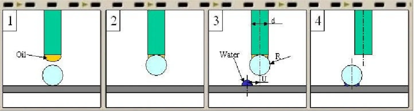
The goal of this work is to realize a microhandling system based on capillary force that uses two different liquids to pick and release the object: a drop of a low surface tension liquid (oil) is used to pick a sphere and a little drop of a high surface tension liquid (water) is used to release it. The concept is shown in Figure 1.
Figure 1 Functioning concept
The objectives are to reach a high reliability for the tasks that the gripper have to execute and to obtain a good positioning precision in the releasing task. Actually the releasing drop has the property to self centre the component on it. This fact is important because it allows the precise release of the object that were previously grasped incorrectly (i.e. misaligned with the gripper axis).
To reach these goals some repeated handling tests have been done, verifying the reliability characteristic. Other tests have been executed with a low releasing velocity to understand better the phenomenon.
First of all, however, a simulation tool has been developed to obtain theoretical results to be compared with the results of the experiments.
3.2 Simulation tool
3.2.1 Problem definition: geometry and forces
[1] There are two classical approaches to estimate capillary force acting between two objects linked by a liquid bridge:
2 an energetic approach that consist in writing the interfacial energy of the system and deriving it with respect to the separation distance between the objects;
2 a geometrical approach that consist in approximating the meniscus shape to a known geometry and using it in the calculation of the capillary force considered sum of Laplace and Tension forces (refer to paragraph 2.1 of this work):
+ = = Force Tension ) sin( 2 curvature) surface mean H tension, surface ( Force Laplace 2 1 1 1 2 1 φ θ γ π γ π γ r F r H F T L (3.1)
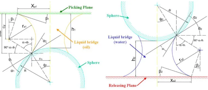
The geometrical approach is chosen with the circular approximation of the meniscus (liquid-vapour interface). The configuration to refer to is the one in Figure 2: the picking tool and the releasing substrate are supposed to be planes.
Figure 2 Geometry of the picking meniscus (a) and of the releasing meniscus (b)
Principal parameters are: 2 R is the sphere radius
2 xa is the radius of the contact line between the plane and the meniscus (we supposed it
to be a perfect circle)
2 Ra is the radius of the contact line between the sphere and the meniscus
2 ra is the principal curvature radius of the meniscus in the figure plane
2 α is the contact angle between the meniscus and the sphere plane 2 β is the contact angle between the meniscus and the plane
2 θ describes points on the sphere surface
3.2.2 The algorithms
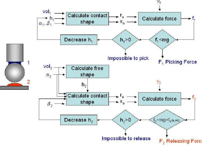
The schemes of the algorithms we followed to estimate the picking and releasing forces and the corresponding distances between the planes and the sphere are reproduced in Figure 3.
In the first algorithm the contact angles are parameters given by the couple liquid-material, while the volume and the separation distance are imposed. Using them it is possible to determine the shape of the meniscus and in particular the parameters ra, xa and Ra. Now
the corresponding force f1 can be calculated by using the formerly written equations. If the
picking force f1 for a given height h overcomes the weight of the sphere mg, this value is the wanted picking force F1. Otherwise the height h must be decreased step by step until
the force is enough or the height is zero. Actually if the height h reach the null value the sphere can not be grasped. The force F1 tend to detach the component from the surface,
so the distance sphere-plane reduces and the force increases as well. Since this phase is irreversible and its energy minimum is reached when the sphere touches the gripping plane (h1=0), the grasping can be configured as an instable process. Actually this position
is the one that satisfies the minimal surface configuration corresponding at the minimum value of the free energy.
The second algorithm refers to the releasing process. In this case it is necessary to calculate, first of all, the height of the water drop laying on the working plane: it is the separation distance. Hereinafter the algorithm follows the same scheme as the first one except for the discriminant force. In this case f2 is the releasing force and, if the sum of f2
and the weight is greater than the picking force f1(h1=0) , it is the wanted releasing force F2. In this case as well the height of the meniscus must be decreased step by step until the releasing process happens or the height itself is zero and in this case the sphere can not be discharged. When the procedure is possible, the sphere is attracted to the releasing plane by the same mechanism explained previously for the picking phase.
3.2.3 Numerical simulation
The iterations included in the algorithms can be easily evaluated by using a computer and a mathematical program. We used the application MATLAB®, that is a high-level matrix/array language with control flow statements, functions, data structures, input/output, and object-oriented programming features. It allows both "programming in the small" to rapidly create quick and dirty throw-away programs, and "programming in the large" to create large and complex application programs.
The program has been structured with a main file that uses two subroutines contained in two secondary files. The main file, called mainsurf.m (see Appendix B), first evaluates the
(using a double loop and calling up the secondary files geom.m and forz.m), then prints a three dimensional graph, that represents the force surface. Later the application returns the picking heights, related to the drop volumes able to overcome the sphere’s weight mg. Then it provides also the picking forces calculated for h=0: Fpick2. Afterwards the program calculates the releasing force for each possible separation distance, for each releasing drop volume and for each previously determined Fpick2. For doing that, the releasing drop’s height H2 must be calculated. H2 has been computed from the following equation (according with Figure 4):
(
)
− = ⇒ − = − = 2 2 2 2 2 2 2 cos 1 cos 3 3 1 β β π H R R R H H R H Vol g g g g cap spherical⇒
(
)
(
)
3 2 2 2 cos 2 cos 1 3 β π β + − = Vol H (3.2) Figure 4 DropThe function file geom.m evaluates the meniscus geometry by calculating the parameters ra, xa, Ra and Vol (volume) while, for a chosen distance h between sphere and plane, the angle θ (theta) varies from zero to thetamax. At the beginning, the file obtains the thetamin angle that is the minimum angle able to define a real geometry. The geometric parameters ra, xa and Ra are calculated by using the following equations obtained by geometrical considerations: + + + = + + + = + ) cos( ) cos( cos ) sin( sin sin β α θ θ α θ θ β a a a a a r r R R h r R r x and Ra = Rsin θ (3.3)
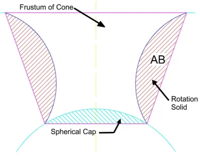
Some studies calculate the meniscus volume as sum of various cylinders which it has been divided into, but, fixed the circle as meniscus shape, it is possible to compute it as difference between the volume of the frustum of cone and the sum of the spherical cap and the rotation solid obtained from the circular segment (Figure 5). For the determination of the rotation solid volume the second Gouldino’s theorem can be used. This theorem calculates the volume by using the area and the barycentre of the plane section AB rotating around the axis (see Appendix A).
Figure 5 Volumes
The function file forz.m calculates the geometrical parameters for a given volume (variable Voldato) by interpolating the results obtained from the previous function “geom” and evaluates the capillary forces for this geometry by using equations (3.1).
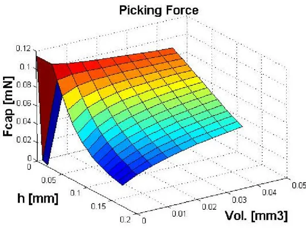
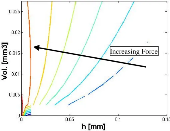
3.3 Results
The program returns plots, both in the picking phase and in the releasing one, of the capillary force varying volume and height of the meniscus. Naturally the two plots are similar (Figure 6 and Figure 7).
It is possible to notice that the capillary force (Fc) grows with the decrease of the distance
between the sphere and the plane (h) much more than it grows with the increase of the volume of the meniscus (Vol). Fixed the height h different from zero, the force raises with the volume. If h is equal to zero, the force has a different trend and it increase reducing the