1
1
1
B
B
l
l
u
u
e
e
t
t
o
o
o
o
t
t
h
h
™
™
t
t
e
e
c
c
h
h
n
n
o
o
l
l
o
o
g
g
y
y
1.1 Introduction
Handheld devices are rapidly becoming an integral part of our daily lives. In most cases, these devices do not have compatible data communication interface, or alternatively if they do, the interface requires cumbersome cable connections and configuration procedures. The continued growth of the use of portable devices in recent years has made it desirable to find better solutions in order to facilitate on-demand connections between devices. An obvious solution would be to get rid of cables and use short-range wireless links. Moreover, such a solution could prove inexpensive, enabling compelling applications, and be universally adopted by device vendors.
From this concept, the idea of Bluetooth™ (BT) arose in order to standardise wireless communications between any and all electrical device replacing classical cable systems. This concept provides powerful added value, embodied by three main goals: small size, minimal power consumption and low price. Small size and low cost is desirable in order to obtain a large diffusion of Bluetooth technology, compared with the alternative of placing cables. Low power consumption is also desirable in view of the fact that devices are often mobile and need to use battery power, such power being optimised as much as possible.
Chapter 1 Bluetooth™ technology
2
1.2 History of Bluetooth™
What is Bluetooth™? The question comes spontaneously when you hear the words Blue-Tooth. This name comes from the tenth-century Danish Viking King Harald Blatand: Blatand in Danish means Bluethooth. He brought warring Viking tribes under a common rule. As he united and controlled Denmark and Norway, therefore, Bluetooth aspires to be the de facto standard in wireless connectivity. Bluetooth™ started in 1994, when Ericsson Mobile Communication began a study to examine alternatives to cables linking its mobile phones with accessories. This study looked at the use of radio links. Only five years later, in July 1999, the specification for Bluetooth wireless technology (version 1.0) came out as consequence. As soon as Bluetooth technology was implemented and produced, it proved to be a very interesting wireless communication system; but as could be expected, there were some concepts that seemed acceptable in theory that did not work optimally when translated into hardware and software. A review version was necessary to address these problems; thus an updated version (1.1) was published in early 2001. Furthermore, thanks to the continued growth and evolution of portable communicating devices in recent years, Bluetooth standard was undergoing continuous improvement in order to answer market expectations. The latest version (1.2) was released in November 2003, and now a further version is under development in order to move a step forward for Bluetooth technology: the
Enhanced Data Rate.
This continuous evolution of Bluetooth’s specification has been possible thanks to the Special Interest Group (SIG), founded in February 1998, by the following group of core promoters:
Ericsson Mobile Communication AB. Intel Corporation.
IBM Corporation. Toshiba Corporation. Nokia Mobile Phones.
Chapter 1 Bluetooth™ technology
3 In May 1998, the core promoters publicly announced the formation of the SIG and invited other companies to participate. In December 1999 four important companies also became members of the SIG: Microsoft, Lucent, 3COM and Motorola. On membership of SIG, a company acquires the right to develop and improve the BT specifications, through various studies or practical tests. Afterwards, results are made available and assist the SIG to decide any possible modification on the Bluetooth standard. Today, new companies may participate in the SIG as adopter companies, obtaining the licence required to implement Bluetooth wireless technology. STMicroelectronics is a member of the BT SIG, and is in fact a Gold Associate Member and within the SIG, it is part of the radio Improvement Working Group and a member of the Roadmapping Committee. At the head of the Bluetooth SIG is the program management board coordinating operation of the entire group. The Bluetooth specifications define the system for the radio up to the higher levels, due to establish an easy and correct link between various devices made by different producers. These specifications are available online at the website www.bluetooth.org for free-download or further information.
1.3 Bluetooth protocol stacks
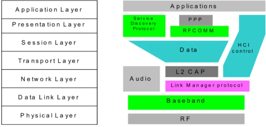
The standard model for every communication system, relative on the communication protocol stacks, is the familiar OSI (Open System Interconnection). Bluetooth follows a particular communication system, quite similar to the model, but they are not exactly matched. In the following figure, the Bluetooth protocol stack layers and the differences among the two models are shown.
The Physical Layer is responsible for the electrical specification of the communication device, including modulation and channel coding. In the Bluetooth system this is covered by the Radio and part of the Baseband. The
Chapter 1 Bluetooth™ technology
4 the radio front end, frequency bands, channel arrangements, permissible transmit power levels, and receiver sensitivity level.
A p p li c a ti o n L a y e r P r e s e n ta ti o n L a y e r S e s s i o n L a y e r T r a n s p o r t L a y e r N e tw o r k L a y e r D a ta L i n k L a y e r P h y s i c a l L a y e r A p p li c a ti o n s R F C O M M L 2 C A P A u d i o L i n k M a n a g e r p r o t o c o l B a s e b a n d R F H C I c o n t r o l D a ta S e r v ic e D is c o v e ry P r o t o c o l P P P
Figure 1.1 – Comparison between OSI and Bluetooth protocol stacks.
The next layer is the Baseband, which carries out Bluetooth’s physical (PHY) and media access control (MAC) processing. This includes tasks such as device discovery, link formation, and synchronous and asynchronous communication with peer. Moreover, Bluetooth is unique in offering the front-end RF processing integrated with the baseband module. In this way, on-chip integration lowers the cost of the network interface and the small size makes it easy to embed Bluetooth chips in devices such as cell phones and PDAs.
The Data Link Layer must check transmission, framing and error control of a specific link, such as overlaps Link Controller and the control end of the Baseband. The Network Layer is responsible of transferring data across the network and encompasses the end of the Link Controller and the beginning part of Link Manager. Bluetooth peers must exchange several control messages for the purpose of configuring and managing the baseband connections. These message definitions are part of the link manager protocol (LMP) .
The Transport Layer is responsible for the connection and transfer of multiplexing data across the network to the level provided by the application, and thus overlaps the high end of the Link Manager and all the Host Controller Interface. The Session Layer provides the management of session and data flow
Chapter 1 Bluetooth™ technology
5 control service, which are covered by L2CAP and the lower end of RFCOMM and Service Discovery Protocol (SDP). Usually, L2CAP and layers above it are implemented in software. L2CAP delivers packet received from higher layers to the other end of the link. The RFCOMM specification defines a method of emulating the RS-232 cable connection on top of the Bluetooth air link.
The Presentation Layer is involved to present a common interface of Application Layer and almost covers the RFCOMM, SDP and the Point-to-Point protocol (PPP). Finally, Application Layer which manages communication between host applications is also the same for Bluetooth.
1.4 Radio Front end
Bluetooth devices operate at 2.4 GHz in the licence-free ISM band (Industrial, Scientific and Medical) where many applications operate, such as microwave ovens or IEEE 802.11; this means that Bluetooth must be robust regarding outside interference. The used band, between 2.4000 - 2.4835 GHz is divided into 1-MHz spaced channels, so the maximum speed available during communication is 1 Megasymbol per second. Nowadays, the available channels are usually 79 and the previous limitation depending on the country (23 available channels for France, Spain and Japan) has now been exceeded. Finally, the transmitted signal at the frequency of ISM band is received and demodulated to obtain a signal within a band of 1 MHz, which is the length of each separate radio channel.
Each Bluetooth device uses a transmission technique based on TDM (Time Division Multiplexing): every time slot lasts 625 microseconds and a packet can be constituted by a single slot, 3 consecutive slots or 5 consecutive slots. In addition, since Bluetooth uses all the band ISM, Frequency Hopping Spread
Spectrum (FHSS) technique is used to solve transmission problems: after each
packet, the radio frequency hops from radio channel to radio channel, in both communicating devices, using a pseudorandom hopping sequence. The algorithm
Chapter 1 Bluetooth™ technology
6 used ensures maximum distance between adjacent channels in the hop sequence, due to guarantee a safe link and good immunity against other sources of interference into ISM band. All communicating devices must know the sequence of the frequency, this knowledge is embedded in the hopping sequence construction algorithm.
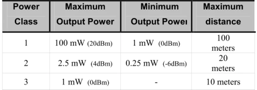
Bluetooth is a low power technology and this implies that the distance between the devices must be short. From this point of view, there are three different radio classes, which correspond to a different operation ranges (see Table 1.1) :
Power Class Maximum Output Power Minimum Output Power Maximum distance 1 100 mW (20dBm) 1 mW (0dBm) 100 meters 2 2.5 mW (4dBm) 0.25 mW (-6dBm) 20 meters 3 1 mW (0dBm) - 10 meters
Table 1.1 – Bluetooth transmit power classes.
There is also a minimum range of 10 cm to be respected between communicating devices, because some receivers may be saturated. Furthermore, Bluetooth offers three different low-power modes for improving battery life: Hold mode, Sniff mode and Park mode, further description remains outside the scope of this report. The initial standard of Bluetooth (versions 1.0 and 1.1) is called “Basic Rate”, and the modulation used is GFSK (Gaussian Frequency Shift Keying). In this way, the transmission of a binary 1 gives rise to a positive frequency deviation from the nominal carrier frequency, while a binary 0 gives rise to a negative frequency deviation. Thus, the maximum bit rate for GFSK modulation is 1 Megabit per second (Mbps). Instead, for the new standard called “Medium Rate” or in the latest version “Enhanced Data Rate” two new modulation types have been selected: π/4-DQPSK and 8-DPSK, which are able to increase the maximum bit
rate up to 2 Mbps and 3 Mbps, respectively. Both will be comprehensively analysed in the following chapters.
Chapter 1 Bluetooth™ technology
7
1.5 Effecting a Bluetooth communication
A Bluetooth device may work in two different ways: as master or as slave. Master is the device which initiates an exchange of data, while the slave responds to the master. The master sets the frequency hopping and the slave has to synchronise to it. It should be underlined that every master and slave has its own BT-Clock and BT-Device Address. This is necessary to guarantee a perfect link between various devices, through an algorithm that calculates the right frequency hop sequence for all devices. When slaves connect to a master, they receive the Bluetooth device address and the clock of the master, which are used to calculate every frequency hop. The master also has the power to divide bandwidth between its slaves determining the number of time slots which should be given to every slave. Furthermore, the device that has the role of master is not fixed, but it can change without simultaneity. The slave is then synchronized in the timing and in the hopping of the master; the master is in turn able to listen for messages coming from the slave; in the next time slot master and slave change channel and retune their radio. Now the slave has to transmit whether it has or has not understood the last message or data. In the next slot, the slave will be able to listen and the cycle goes on. The master, however, has the freedom to decide to transmit or not to transmit. The slave will not transmit again unless it is polled by the master.
There are usually two different ways in which all Bluetooth devices are linked: piconet or scatternet. A set of BT devices sharing a common channel is called
piconet. As shown on the left side of Figure 1.2, a piconet is a star-shaped
configuration in which the device at the centre performs the role of master and all other devices operate as slaves. All slaves must follow the frequency hopping and timing of the master. Every slave has a link with the master, but there are no direct links between slaves. Up to seven slaves in active mode can be served simultaneously by the master, or they may be linked using a scatternet.
A scatternet is formed by interconnecting multiple piconets. As shown on the right side of Figure 2, the connections are formed by bridge nodes, which are
Chapter 1 Bluetooth™ technology
8 members of two or more piconets. This means that one device is member of more than one piconet, spending some time slots in one piconet and some in another piconet. After staying in a piconet for some time, the bridge can turn to another piconet by switching to its hopping sequence. In a scatternet, it is quite possible that a device could be master in one piconet and slave in another piconet, or slave in two picontes. But it cannot be a master of two piconets simultaneously, since all the slaves should be synchronised to it. It is useful to remark that more piconets in an area means more packet collisions, because the devices are not now synchronised to the same master and consequently the data rates may decrease. Clearly, this not only happens to independent piconet but also to scatternets.
Master Slave Master
Slave Slave Slave Slave Slave Bridge Node
Figure 1.2 – Piconet and Scatternet.
Bluetooth technology is able to connect devices which move continuously and sometimes go out of range; for this reason the network topology change continually, called an ad hoc network. Therefore, a special discovery protocol is needed. Bluetooth uses a procedure known as inquiry for discovering other devices; it uses paging to subsequently establish connections with them. Both inquiry and paging are asymmetric procedures that involve the inquirer and the inquired (as well as the pager or the paged) devices to perform different actions. This implies that when two nodes set up a connection, each needs to start from a differential initial state; otherwise, they would never succeed in discovering each other. The profile specifications play an important role here, defining the required initial state for each device in each usage scenario. A symmetric procedure for establishing connections is an ongoing topic of research.
Chapter 1 Bluetooth™ technology
9 The inquiry and paging are conceptually simple operations, but the frequency-hopping nature of the physical layer makes the low-level details quite complex. Two nodes cannot exchange messages until they agree to a common channel-hopping sequence as well as the correct phase within chosen sequence. Bluetooth solves this problem simply by mandating the use of a specific inquiry-hopping sequence known to all devices. During inquiry, both nodes hop using the same sequence; but the sender hops faster than the listener, transmitting a signal on each channel and listening between transmissions for an answer. When more than one listener is present, their replies may collide. To avoid any collision, listeners defer their replies until expiration of a random back off timer. This implies a longer procedure time for setting up the communication among devices (this problem has been solved in the 1.2 BT specifications, as shown in the next paragraph).
Paging is the procedure which two Bluetooth devices, a master and a slave, carry out to initiate the connection, by addressing a request directly. The communication steps during the paging procedure are similar to the inquiry, except that the paging message is unicast to a selected listener, so the listener need not back off before replying. The sender also has a better estimate of the listener’s clock, which enables it to communicate with the listener almost instantaneously. Upon receiving an ACK for the paging message, the sender becomes the master and the listener becomes the slave of the newly formed piconet, and both nodes switch to the piconet’s channel-hopping sequence. Later, if necessary, the master and slave roles can be swapped.
At the end, when a BT device is switched on, but communication with an another device does not exist, this is called the standby state. During this time, the device is inactive and the radio is switched off in order to avoid the detection of any inquiry message. After these stages, the connection state starts the communication in real terms. All of these states and relative procedures are managed by the Link Controller, which follows the specifications given by Link Manager Protocol (LMP).
Chapter 1 Bluetooth™ technology
10
1.6 Syncronous and Asyncronous links
There are two different communication types according to the different data that should be exchanged: SCO and ACL. The SCO (Synchronous Connection Oriented) packet is used for voice or audio communication, while ACL (Asynchronous Connectionless) packet is used for data communication.
ACL links
After a connection between a master and a slave is established, an ACL link is also settled. While a master may have several ACL links to different slaves at any one time, only one link may exist between two devices. A master can decide independently when to exchange data with a slave, so ACL packets provide a packet-switched connection but data are only sent from the high level. This scheme has two advantages: the master can ensure that slave transmissions do not collide; and the slots can be allocated to satisfy the quality of service (QoS) requirement of each ACL. The master can grant more bandwidth to a slave by polling more frequently or by changing the packet size. ACL packets carry data from the L2CAP layers, because all user data is sent by L2CAP and passed to the Baseband. A slave may only respond with an ACL packet in the next slot after having been addressed by a master. There are also ACL broadcast packets which are not directed to a specific slave but are in fact received by every slave.
SCO links
This link is symmetric between a master and a slave because of its has reserved channel bandwidth and reserved timeslots to exchange data in periodic regular times. It provides a circuit switched connection and is therefore suitable for applications time bounded such as audio or voice. For this application retransmission is not possible and SCO packets are sent only once. In this way, it is necessary that data packets are protected with a particular correction code. Inside data packets the Forward Error correction (FEC) code is used. It is useful to
Chapter 1 Bluetooth™ technology
11 the demodulation block in order to check and reduce errors that could possibly be received. A master can support up to three SCO links to the same slave or to different master; a slave can support up to three SCO links from the same master. The parameter that defines the time in which the master regularly sends SCO packets to the slave, is the Tsco and usually is called “SCO interval” and is
measured in time slots. The slave has been granted the ability to respond with SCO packet in the reserved time slots. In the event that decoding of the Packet Header is not correct, the slave might still respond in the reserved slot. The master is not allowed to transmit in reserved slots, except for a broadcast LMP message. When an SCO link is set up, the reserved slots are specified such as the SCO interval, Tsco and the starting offset, Dsco. A device must schedule the ACL packet
around reserved SCO slots in order to preserve their integrity; the only exceptions are Link Management control packets which can override SCO links.
1.7 Bluetooth specifications 1.2
Bluetooth standard is continuously in evolution in order to adapt to the needs of new faster applications. New features have been introduced with the BT specification 1.2, to reduce interference generated by Bluetooth devices towards other wireless systems working in the same ISM band; to increase immunity of Bluetooth devices against interference generated by other non hopping systems and to improve performance by reducing missed acknowledgements. Attention is focused on the principal innovations introduced within the new specifications. Adaptive Frequency Hopping (AFH) is the new technique used to optimise the frequency hopping of the communicating devices. The master has the task of making a channel classification to decide which channels will be avoided (unused channels) and which shall be used (used channels). In this way, the number of channels can be reduced from 79 to N, where N is at least 20 and only used channels are selected, in order to optimise every time slot. A specific re-mapping
Chapter 1 Bluetooth™ technology
12 function is used to re-map unused channels to used ones, which is based on the master clock to guarantee randomness. The slave can also undertake channel assessment. The host device may also indicate what frequency may not be used. A new feature is the single channel: an unique frequency used for the transmission of the master-to-slave packet and for the slave-to-master response, improving the efficiency of the ARQ procedure and the computation of the frequency selection algorithm.
The SCO links of version 1.1 have 64 kbps symmetric traffic and limited performance in case of degraded channels. The new extended SCO links (eSCO) overlap the limit providing high data rates, synchronous data streaming capability, guaranteed error rates and enabling asymmetric SCO traffic. These features are an ideal support for foreseen applications such as higher quality voice (headset/microphone), access to a video conference service from a data terminal via a 3G gateway, access of car functions using an in-car device, etc.
The need of a faster connection rises when consideration is given to the fact that the default inquiry period has a gap depending on the back off time and that paging timing can be elongated if in the wrong train. The new faster connection has the target to improve the connection time when connecting to known or unknown devices. A possible solution is to send the first FHS soon after having got the first hit, thus guaranteeing that all devices will answer before the gap time, although on average this does not speed up the connection time. Another problem occurs when a device is waking up in the wrong train, because the next train has to be waited for adding a little delay. To solve this problem the device under inquiry may perform an “Interlaced scan”, that means effecting a double scan, on both trains, with an increase in power consumption.
Chapter 1 Bluetooth™ technology
13
1.8 Next generation of Bluetooth
The Enhanced Data Rate (EDR) 1 mode provides an extension of the Bluetooth specification by adding new packet types. This standard introduces several changes within Radio and Baseband specification parts. Enhanced Data Rate provides a two-fold and optionally a three-fold increase in the data rate during the Payload portion of certain packet types. A robust PSK scheme has been chosen to simplify the hardware integration of EDR in the Bluetooth radio. Π/4-DQPSK or 8DPSK are the modulation applied depending on the propagation conditions. Whether or not a device is capable of supporting the Enhanced Data Rate is indicated in the LMP_features message. A EDR capable device may support the 2Mbps mode only or both 2Mbps and 3Mbps. Only the master can enable Enhanced Data Rate mode on ACL and/or extended SCO (eSCO) link separately for each of the EDR capable slaves in the piconet. Enhanced Data Rate is an optional feature that can be used to complement the Basic Rate operation of a Piconet (Bluetooth 1.1) or in combination with the new Radio improvements (Bluetooth 1.2).
In fact, every data packet always starts with an Access Code and a Header Code modulated by GFSK and if needed the Payload can be transmited with the two new modulation type to improve the data rate. This feature has been chosen in order to guarantee an entire compatibility with the basic GFSK standard, but in this way, the resulting packet structure is more complicated. Data transmission through the new modulation types needs a Guard Time to separate the two kind of modulations and a Synchronous Sequence useful for the new timing recovery. The specifications of the Bluetooth feature relative to upper stack layers are outside this scope. The next chapters focus attention on the Radio and Baseband parts.
1 The previous name “Medium Rate” (MR) of the new BT standard has been changed in the new