POLITECNICO DI MILANO
School of Industrial and Information Engineering
Master of Science in Electrical Engineering
Comparison between Induction, Permanent
Magnets and Synchronous Reluctance Motors for
Electrical Railway Traction Applications
Supervisor:
Prof. Morris BRENNA
Co-supervisor
Ing. Piero MOIA
Master Thesis of:
Gianluca CONIGLIARO
ID: 884869 Academic Year 2018-2019
Indice
Indice ... iii
INDICE DELLE FIGURE E TABELLE ... v
ABSTRACT ... 1
SOMMARIO ... 2
1 SYNCHRONOUS RELUCTANCE MOTOR: INTRODUCTION AND STATE OF THE ART .. 3
2 MATHEMATICAL MODEL AND DESIGN ASPECTS ... 7
2.1 MATHEMATICAL MODEL ... 7
2.1.1 Magnetization characteristics ... 10
2.1.2 Cross saturation effects ... 13
2.1.3 Effect of iron losses ... 15
2.2 Design features ... 18
2.2.1 Classification based on the rotor design ... 18
2.2.2 Flux barriers shape ... 20
2.2.3 Flux barriers geometry ... 22
2.2.4 Tangential and radial ribs ... 26
2.2.5 Influence of the air-gap ... 28
2.2.6 Influence of the number of poles ... 28
2.3 Control and operating domain aspects ... 30
2.3.1 Operating limit points ... 30
2.4 Different control strategies ... 36
2.4.1 Maximum power factor control strategy ... 36
2.4.2 Maximum Rate of Change of Torque Control ... 37
2.4.3 Field Weakening Control ... 37
3 COMPARISON BETWEEN SynRM AND INDUCTION MOTORS ... 41
3.2 Analytical Comparison ... 43
3.3 Characteristics and difference between the two motors ... 45
4 COMPARISON BETWEEN PERMANENT MAGNETS MOTORS AND SYNCHRONOUS RELUCTANCE MOTOR ... 53
4.1 Characteristic Materials: Rare-Earth... 53
4.2 PMSM: Advantages and Disadvantages ... 58
4.3 Failure Issues for a Permanent Magnets Synchronous Machine ... 62
4.4 Demagnetization risk for a permanent magnet ... 65
5 SYNCHRONOUS RELUCTANCE MOTORS IN TRACTION APPLICATIONS ... 67
6 SIMULATION RESULTS: COMPARISON BETWEEN INDUCTION AND SYNCHRONOUS RELUCTANCE MOTORS ... 71
6.1 Parameters Calculation ... 71
6.2 Simulation results ... 75
7 COMPARISON BETWEEN IPM AND SYNRM IN RESPONSE TO DIFFERENT FAULT CONDITIONS ... 83
7.1 Classification of Industrial Motor Faults ... 85
7.2 Simulation results ... 87
7.2.1 Comparison Between SynRM and IPM when an uncontrolled generator fault condition occurs ... 87
7.2.2 Comparison Between SynRM and IPM Motors When Symmetrical Short-Circuit Occurs ... 91
7.2.3 Comparison Between IPM and SynRM When Phase-to-Phase Short-Circuit Occurs ... 102
8 CONCLUSIONS ... 109
INDICE DELLE FIGURE E TABELLE
Fig. 1.1 Example of isotropic (a) and anisotropic (b) rotor structure. ... 4
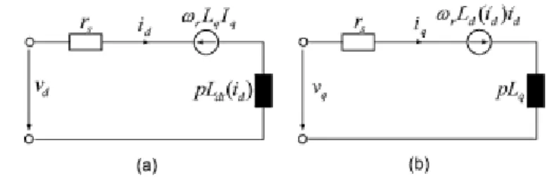
Fig. 2.1 Example of ideal equivalent circuit of d-axis (a) and q-axis (b) in dq reference frame ... 8
Fig. 2.2 Example of phasor diagram of SynRM [3] ... 11
Fig. 2.3 Example of magnetization characteristic of the two axes neglecting cross-saturation [3] ... 13
Fig. 2.4 Example of equivalent circuits in rotor reference frame including iron losses, d-axis circuit (left) and q-d-axis circuit (right) ... 17
Fig. 2.5 Example of cross-section of TLA rotor [66] ... 19
Fig. 2.6 Example of TLA rotor ... 19
Fig. 2.7 Example of section of ALA rotor [66] ... 20
Fig. 2.8 Example of ALA rotor ... 20
Fig. 2.9 Example of different barrier's shape ... 22
Fig. 2.10 Example of TLA rotor with cut-off (a) and without cut-off (b) [8] ... 22
Fig. 2.11 Example of machaon rotor structure [7] ... 24
Fig. 2.12 3U and I2U rotor example [7] ... 25
Fig. 2.13 Example of four-pole TLA rotor [10] ... 27
Fig. 2.14 Current limit circle, voltage limit ellipse and MTPA trajectory in the d-q currents plane [67] ... 31
Fig. 2.15 Example of FOC structure for SynRM [37]. ... 39
Fig. 2.16 Example of DTC structure [68] ... 40
Fig. 3.1 Example of Induction (left) and Synchronous Reluctance (right) motors topologies ... 42
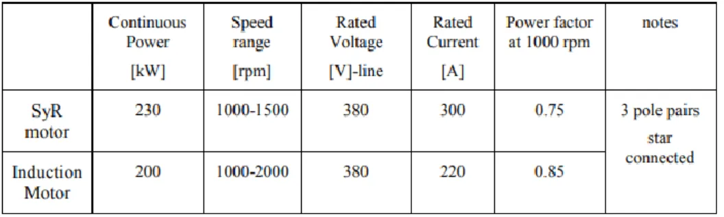
Fig. 3.2 Parameter comparison between IM and SynRM [17] ... 47
Fig. 3.3 Parameters of SynRM for air-conditioning compressor [18] ... 48
Fig. 3.4 IM and SynRM of 250 kW ... 51
Fig. 4.1 Trends of consumption for rare-earth materials over recent years ... 57
Fig. 4.2 Trends of price for rare-earth elements over recent years ... 58
Fig. 4.3 Parameters comparison between IPM,SMPM and SynRM for air-conditioning compressor application ... 60
Fig. 6.1 Inductance relationship as function of power for different air-gap length [3] . 74 Fig. 6.2 Load torque profile applied to SynRM. In the y-axis the values of torque are reported in Nm ... 76 Fig. 6.3 Reference (blue line) and measured (red line) speed of SynRM ... 77 Fig. 6.4 Reference (yellow line), measured (blue line) and load (green line) torque of SynRM over time ... 77 Fig. 6.5 Reference and measured speed [rpm] of IM for different load conditions ... 79 Fig. 6.6 Measured (yellow line) and load (red line) torque for IM ... 79 Fig. 6.7 Amplitude of Apparent power as function of time for IM delivered from the inverter ... 81 Fig. 6.8 Amplitude of apparent power consumption for SynRM ... 81 Fig. 7.1 Different Speed reference imposed to IPM motor as function of time ... 87 Fig. 7.2 Stator voltages in dq reference frame at different speeds in Uncontrolled Generation Fault ... 88 Fig. 7.3 Phase currents of IPM at different speed in Uncontrolled Generation Fault ... 88 Fig. 7.4 Electromagnetic torque of IPM as function of time in Uncontrolled Generator Fault conditions. ... 89 Fig. 7.5 Phase-to-phase voltages of IPM during Uncontrolled Generator Fault ... 89 Fig. 7.6 Reference speed imposed to IPM in a three-phase short circuit fault condition ... 94 Fig. 7.7 Electromagnetic Torque as function of time in healthy and three-phase short-circuit fault conditions ... 94 Fig. 7.8 Phase currents of IPM in healthy and three-phase short-circuit fault conditions ... 95 Fig. 7.9 Zoom of phase currents diagram in healthy and three-phase short circuit fault conditions ... 96 Fig. 7.10 Zoom of IPM torque in healthy and three-phase short circuit fault conditions ... 96 Fig. 7.11 q-axis current of IPM in healthy and three-phase short circuit fault conditions ... 97 Fig. 7.12 d-axis current of IPM in healthy and three-phase short circuit fault conditions ... 98
Fig. 7.13 Phase currents of IPM in healthy and three-phase short circuit fault conditions at motor terminals with the opens of circuit breaker between inverter and the motor ... 99 Fig. 7.14 Electromagnetic torque for IPM in healthy and faulty conditions when a three-phase short circuit occurs at the motor terminals and a circuit breaker is put between the inverter and the motor ... 99 Fig. 7.15 Speed reference imposed to SynRM ... 100 Fig. 7.16 Electromagnetic torque for SynRM in healthy and faulty conditions when a three-phase short circuit occurs ... 101 Fig. 7.17 Phase currents of SynRM in healthy and faulty conditions when a three-phase short circuit occurs ... 101 Fig. 7.18 IPM electromagnetic torque as function of time in healthy conditions and during phase-to-phase short circuit fault ... 102 Fig. 7.19 Zoom of torque behaviour of IPM in healthy conditions and during phase-to-phase short-circuit fault ... 103 Fig. 7.20 IPM phase currents in healthy and phase-to-phase short circuit fault conditions ... 103 Fig. 7.21 d-axis currents of IPM in healthy conditions and during phase-to-phase short circuit fault ... 104 Fig. 7.22 Zoom of d-axis current behaviour between t=1.29 s and t=1.81 s ... 104 Fig. 7.23 Phase-to-Phase voltages ... 105 Fig. 7.24 SynRM electromagnetic torque in healthy conditions and during phase-to-phase short-circuit fault ... 106
Table 1 Efficiency values of IM and SynRM at different load conditions at speed of 1500 rpm ... 82 Table 2 Parameter of IPM used for simulations ... 84
1
ABSTRACT
The purpose of this thesis is to conduct an analysis of the applicability of Synchronous Reluctance motors for the electrical railway traction applications. In summary, the aim of this thesis is to evaluate possible solutions, free from permanent magnet applications, able to realize an electromechanical power conversion with the required performance characteristics, reliability and ease of use. This solution has been identified with the Synchronous Reluctance motors and the advantages and disadvantages of these particular machines will be highlighted compared to other common types of machines more used in the industrial field. In the various chapters of the thesis it will be first illustrated the theoretical aspects of the mathematical model that describes the behavior of the Synchronous Reluctance motor, the aspects relating to the regions of operation and the control strategies adopted. Furthermore, the characteristic parts that constitute the rotor structure in terms of design will be presented. Subsequently, comparisons will be introduced based on the main characteristics of these motors in comparison with Induction motors and Permanent Magnet Synchronous motors by conducting a bibliographic search on existing realities in the industrial field. Comparisons will be made as regards the performance in terms of efficiency for the comparison with the induction motor and as regards the comparison with the Permanent Magnet motor, the focus will be on behavior in different fault conditions. It will then be illustrated how the Synchronous Reluctance motor can be a good alternative in terms of performance and reliability for its possible use for the electrical railway traction applications.
2
SOMMARIO
Lo scopo di questa tesi è di condurre un'analisi dell'applicabilità dei motori Sincroni a Riluttanza per le applicazioni di trazione elettrica ferroviaria. In sintesi l'obiettivo di questa tesi è valutare possibili soluzioni, libere da applicazioni di magneti permanenti, in grado di realizzare una conversione di potenza elettromeccanica con le caratteristiche prestazionali richieste, affidabilità e facilità di utilizzo. Questa soluzione è stata identificata con i Motori sincroni a riluttanza e i vantaggi e gli svantaggi di queste particolari macchine saranno messi in evidenza rispetto ad altri tipi comuni di macchine più utilizzate in ambito industriale. Nei vari capitoli della tesi saranno prima illustrati i fondamenti teorici del modello matematico che descrive il comportamento del Motore sincrono a riluttanza, gli aspetti concernenti le regioni di funzionamento e le strategie di controllo adottate. Inoltre saranno presentate le parti caratteristiche che ne costituiscono la struttura del rotore in termini di design. Successivamente saranno introdotti dei confronti basati sulle caratteristiche principali di tali motori in confronto con i motori a Induzione e i motori sincroni a Magneti permanenti eseguendo una ricerca bibliografica su realtà già esistenti nel campo industriale. Saranno effettuati confronti per quando riguarda le prestazioni in termini di efficienza per il confronto con il motore a induzione e per quanto riguarda il confronto con il Motore a magneti permanenti ci si concentrerà sul comportamento in diverse condizioni di guasto. Verrà quindi illustrato come il Motore sincrono a riluttanza può essere una buona alternativa in termini di prestazioni ed affidabilità per un suo eventuale utilizzo per la trazione elettrica ferroviaria.
3
1 SYNCHRONOUS RELUCTANCE MOTOR:
INTRODUCTION AND STATE OF THE ART
Electrical motors had been used in traction applications for more than 100 years, during these years different kinds of motors have been used. The electrical traction represents an interesting field in a period in which the decreasing of air pollution is one of the most important topics for the major economic of the world, and the electric motor represent the beating heart of a traction system. Two topologies can be remarked for this application: Direct Current Motors (DCM), and Induction Motor (IM). With the increasing need to reduce masses and improve efficiency it has led to a growing interest in recent years to synchronous motors. In traction applications, such as railway or electric vehicle the alternative to Induction Motors is represented by Permanent Magnet Synchronous Motors (PMSM). These types of motors which rely on the performance characteristics of the permanent magnets in recent years have represented the favourably solutions by the manufacturer mostly for electric vehicles where high values of torque density are required. Unfortunately, permanent magnets utilization leads to higher cost to buy raw material (the magnets itself made of “rare earths”) that is not welcomed by traction drives manufactures and customers too. As several authors and researchers have showed interest in this type of motors, and in some fields the substitution of drive equipped with Induction or Permanent Magnets motors with the Synchronous Reluctance ones it is already an operational reality. A Synchronous Reluctance motor show in terms of stator’s structure the same one of the Induction and the Permanent Magnets motors ones, a typical distributed three-phase winding architecture was considered in the analysis. The main difference which this type of motor presents is located on the rotor structure. Unlike the most used motors in industrial applications such as the Induction and the Permanent Magnets one, a Synchronous Reluctance motor doesn’t have any winding or magnet on the rotor. The mechanism for the torque production is based on the reluctance concept, which is the only reason that allows this motor to generate torque. This concept is very
4
basic and it has a very old history and it can be traced back to before the beginning of 20th century. The phenomenon of the reluctance torque is due to the magnetic anisotropy of the rotor structure which creates a difference in the flux path so the flux lines of the magnetic field which is created only by the stator’s windings follow the path whit the minimum reluctance. In this situation the rotor axis with minimum reluctance tends to align with the stator’s field creating a sort of distortion field. In fact for the sake of reducing the whole system potential energy to reduce the field distortion, the reluctance torque is produced to align the d− axis of the rotor with the magnetic field. This is made possible if exists an angle difference between the direct axis and the magnetic field lines. This would not be possible if we were in presence of an isotropy structure. In other words in an energized system a simple salient rotor will tend to align with the core when the coil is energized in order to maximize inductance or minimize magnetic reluctance.
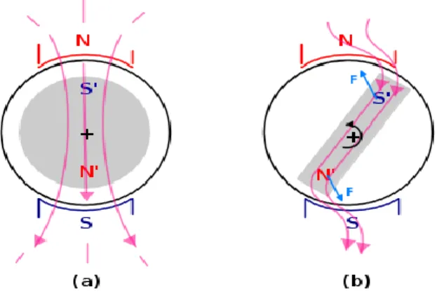
Fig. 1.1 Example of isotropic (a) and anisotropic (b) rotor structure.
The two figures show an isotropy (a) and an anisotropy structures (b) inside a magnetic field. If the isotropic structure is considered due to the fact that the pole pieces induced on the rotor result at any instant facing with the stator’s pole pieces the attraction forces in the rotor produce a set of forces with zero moment which don’t put in rotation the rotor. Instead if it is selected a rotor of anisotropic type the attraction forces form a couple of forces with non-zero moment such that the rotor is put on rotation. In this condition if a load torque is applied on the shaft which
5
maintains constant the angle between the direct axis and the magnetic field, the input electromagnetic energy will be continuously converted into mechanical energy.
This motor was among the most recent solutions in which an interest has been developed thanks to the advantage which show such as the low inertia of the rotor, the high power-weight ratio, the good performance in terms of acceleration, low cost of materials and simplicity of manufacture. These motors have several applications in the textile industry, in that of the glass, in the field of the plastic and in each of that fields which require a constant speed when there is a change in the applied load. Also are found applications of the Synchronous Reluctance motor in the heating systems and in the air conditioning systems or more commonly in the water distribution systems and in the waste water treatment. These motors are ideal for that type of applications which present variable load, with show a quadratic relationship between load torque and speed. Performing a research on the various models available on the market entered by the constructors, it is shown as the range of products provide several sizes and the range of power goes from 1,1 kW to 315 kW at a speed of 1500 rpm. Between the main characteristics which are put in evidence by the manufacturers there are a perfect adjustment on the structure of the machine, a very high efficiency in all the speed range and load, an high power available on the shaft in with respect to the external volume, a reduced moment of inertia of the rotor, high rotation accuracy and at the end a very low acoustic noise.
Considering the efficiency standards, set by the International Electrotechnical Commission, the obtained efficiency varies from IE2 (High efficiency) to IE4 (Super premium efficiency), but is more near to IE2 at relatively lower power levels. These motors reach levels of efficiency IE4 more or less between 11 kW and 15 kW. They have also good performance at low speeds. The Synchronous Reluctance motors are resulted very feasible for the applications such as compressors, pumps and fans. There are also applications in the aeronautical field for the motor drives of the airplane. With its high efficiency maintained at partial load, the Synchronous Reluctance motor represents the ideal solutions for all that industrial applications which don’t need the constant use of nominal power and need to save energy and high efficiency in order to respect the industry regulatory requirements. The robustness of this construction is
6
proved by applications already existing and operatives. In the electrical railway traction applications it happens that if there is no need to put two motor in parallel connected to a single inverter, sometimes this situation can occur in high speed locomotives, the Induction motor can be replaced by a synchronous one, but for example in the subway this doesn’t occur.
The Synchronous Reluctance machine is also employed in a generator mode in those applications such as wind turbines and mini hydroelectric plants.
In [1] the authors present a reluctance machine for high power and speed applications used for the development for a flywheel for hybrid and electric vehicle.
7
2 MATHEMATICAL MODEL AND DESIGN ASPECTS
2.1 MATHEMATICAL MODEL
The rotor of a Synchronous Reluctance motor (SynRM) doesn’t have any winding and magnet and is made only by ferromagnetic material. So due to the fact that must be of anisotropic type in order to develop torque, in terms of geometry it is fundamental that the rotor presents an high saliency ratio which is given by the ratio between the d-axis inductance and the q-d-axis inductance. The rotor is designed in order to have the minimum reluctance in the d-axis, and the maximum reluctance in the q-axis. The saliency ratio is an important parameter for this type of machine, and it is optimized by choosing a suitable geometry of the rotor and a good combination between slots/number of poles for which regards the stator structure.
The mathematical model which describes this motor can be derived from the motor which belongs to the category of AC brushless motors, with the main difference that the flux generated by the magnets and linkage with the stator windings is equal to
zero. Firstly as a starting point in this paragraph in order to derive the conventional model of the Synchronous Reluctance machine the following hypothesis are made:
- The eddy currents in the stator and rotor’s ferromagnetic cores are neglected ; - The rotor is considered totally without windings, also the damping winding are
not considered ;
- For the computation of the inductances only the fundamental harmonic of the magnetic field distribution at the air-gap is considered, so the magnetic circuit is considered totally linear and the inductances assume a constant value. The vector equation of a SynRM expressed in a fixed stator reference frame is:
8
From the equation (1) can be derived the space vector of the flux linkage with the stator windings:
∫( ) (2)
If now it is considered a reference frame based on the position of the rotor with the axis with maximum reluctance aligned with the q-axis, and the axis with minimum reluctance aligned with the d-axis and so with higher values of flux density the following electrical equations can be obtained for which regards the stator windings:
(3) (4)
In which: - , are the space vector of stator’s voltages of the two axes; - is the stator phase resistance;
- are the dq-axes components of the current’s space vector;
- p is the number of pole pairs, is the mechanical rotational speed of the motor;
- are the dq-axes inductances;
9
The space vector which represents stator flux linkage could be also represented by its components along the d-q axes:
(5)
(6)
Carrying out the energy balance in terms of power and by separating the different components it is obtained the expression of the electromagnetic torque developed by the motor:
( ) (7)
( ) (8)
If the two currents components are expressed as:
(9)
(10)
where is the angle between that the space vector of current forms with the d-axis in the d-q plane.
The electromagnetic torque could be expressed also in terms of this angle:
( ) (11)
This expression is useful if the optimum angle for the maximum production of torque for a given current is required, and in this ideal case it results equal to 45°. But as it will
10
be seen in the following part of this thesis this angle is subject to change when the effect of magnetic saturation and iron losses will be considered.
The expressions (7) and (8) show as the electromagnetic torque depends on difference between the values of the two axes inductances and so it is strongly affected by a suitable rotor geometry and optimization which are both factors which improve the torque capability of the motor.
The expression of the torque ripple could be expressed as:
(12)
The saliency ratio is expressed:
(13) Disregarding the phase stator resistance in the mathematical model and making use of the phasor diagram the power factor can be expressed as (2):
( ( )) (14)
The maximum power factor achievable by the motor is:
(15)
Hence the average torque depends on the inductance’s difference, while the power factor depends on the saliency ratio. It is so clear from the obtained equations that in order to develop high values of torque it is necessary to increase the saliency ratio and so the inductances difference.
2.1.1 Magnetization characteristics
The model previously obtained it is an ideal model, as in the real operating conditions due to the presence of ferromagnetic material the relationships between fluxes and respective currents are not linear. This is cause of a variation of the inductance which
11
doesn’t assume any longer a constant value. These effects of non-linearity are the self-saturation and the cross-self-saturation.
The inductances of the two axes are given by the sum of two terms, which are the magnetizing and the leakage inductance:
(16)
and for the fluxes:
(17)
Fig. 2.2 Example of phasor diagram of SynRM [3]
Looking at the phasor diagram it can be expressed the magnetizing fluxes of the two axes as:
(18)
12
where is the angle between the d-axis and the magnetizing flux space vector in the d-q plane.
For the saturation effects are take in consideration only the magnetizing inductances because these are responsible for the torque production of the SynRM, while it has been established as the leakage inductances have a more considerable effect on the power factor. The risk of saturation is much higher for d-axis flux as the path follow by the flux density is higher in the ferromagnetic materials, while, the presence of flux barrier in the q-axis path, made of non-ferromagnetic material (mainly by air), reduces considerably the risk of saturation for the q-axis inductance. Please check the illustration in the following paragraph. The construction of the magnetic flux path takes into account these considerations and the design of the tangential and radial ribs is done to set the ferromagnetic saturation and the relevant inductances of the machine, the design considers also the mechanical robustness of the structure.
It can be reported for general purpose the general expression of the magnetizing inductance concerning the fundamental harmonic:
( ) (19)
where
- m is the number of phases of the motor ; - is the effective air-gap lenght ; - is the external diamater of the rotor ; - is the active conductor lenght ;
- is the winding factor for the fundamental harmonic ; - N is the number of turns per phase ;
- p is the number of pole pairs ;
The equation (19) shows as the magnetizing inductance is inversely proportional to the pole numbers of the machine, and so by increasing this number the magnetizing inductance decrease. The d-axis magnetizing inductance decrease
13
more rapidly due to the difference of the air-gap length between the two axes caused by the presence of the flux barriers in the q-axis. This affects also the saliency ratio and so the power factor of the machine. Hence if the performance of the machine has to be maintained the diameter D must be increased and so the size of the machine is higher [4].
Fig. 2.3 Example of magnetization characteristic of the two axes neglecting cross-saturation [3]
2.1.2 Cross saturation effects
Another non-linearity effect which affect the performance of the Synchronous Reluctance motor is the magnetic dependency of the fluxes of one of the two axes with the current of the other axis, that is the magneto-motive force which sustain the d-axis flux affects the capability of the magneto-motive force of the q-axis of generate the flux and vice-versa generating a coupled effect. Hence the two magnetic circuits are not decoupled and the two fluxes generations are not independent from each other. All that has an effect on the inductance that can be expressed in the following way to represent this phenomenon:
( ) ( )
(20)
14 ( ) ( )
(21)
Applying the (21) and the (20) to equations (3) and (4) with the relationship:
(22)
this relationship derives from the assumption that the system is conservative, and takes to the equation of the following models [5]:
( ) ( ) (22) with: ; . (23)
These relationships can be interpreted as the inductances and determine the steady state average value of the induced e.m.f and torque; while the transient inductances (23) affect the variation of currents and fluxes and created an additional term of disturbance induced voltage which depends on the degree of magnetic coupling.
The cross-saturation effect is mainly due to the iron part shared by the two axes in particular for the bridges. Such effect of magnetization has important consequences on what are the control strategies to adopt for the electrical drive, mostly when high values of torque are required.
Several studies have analyzed the effect that such phenomenon have on the motor performance, focusing in particular on the influence on the difference between the inductances and on the salience ratio, since they are the main parameters that characterize the performance of the machine. In [2] this phenomenon is analyzed according to the load conditions. It emerges that at constant current at low loads
15
there is an increase in the difference between the inductances with respect to the conditions in which saturation is neglected and less at full load, in these conditions the direct axis inductance is little influenced while there is a considerable reduction of the q-axis inductance in particular precisely to smaller currents, which leads to the conclusion that a control which maintains the constant current is preferable.
The magnetic coupling between the two axes has effect also in the performance of the motor at overload conditions. This effect was further investigated in [6] where a comparison was made between the torque curves with equal to zero and different from zero.
Also here it emerges that the effect of cross-saturation on the maximum torque value is lower at nominal current, while increasing the current this effect becomes more and more pronounced. Another aspect highlighted in this article was the difference between the location of the points on the plane of the currents of the two axes at maximum torque per current in the presence of cross-saturation and in absence and how this curve goes towards higher current angles, requiring for a given torque, an higher "d" axis current to balance the saturation effect.
2.1.3 Effect of iron losses
It is also important to consider the effect that iron losses have on motor torque production, which leads to the development of a modified equivalent circuit compared to the ideal one seen so far. In an AC machine the iron losses have a close dependence on the supply frequency and on the voltage. The iron losses in a Reluctance Synchronous machine occur in the two parts of the ferromagnetic structure: the stator and the rotor. The losses in the stator have the same origin as those of the stator of another conventional machine such as the Induction one. The rotor of a SynRM is ideally considered without losses, but in reality the rotor can be subjected to fluctuations at high frequency caused by the interaction between the laminations and the stator teeth. So if the rotor design is not optimized these losses can be considerable high.
16
In this model the total current of each axis does not no longer coincide with that of magnetization as in the ideal case.
(24)
represent the components of leakage current in the ferromagnetic core in
the reference system of axes "d" and "q". So it is clear how the total current used to fed the circuit is not used by the machine completely to produce torque. For the definition of this model an equivalent resistance is defined which represents the iron losses both in the stator and in the rotor. The stator equations therefore referred to the reference system on the two axes becomes the following:
( )
( )
(25)
The magnetization fluxes can be obtained in the following manner:
∫ ∫
(26)
In equations (26) it is highlighted how the two magnetization fluxes are affected by the mutual coupling and the iron losses.
In conclusion, as well as for the equations of state of the voltages it can also write the expressions relative to the average torque, affected by these phenomena:
17
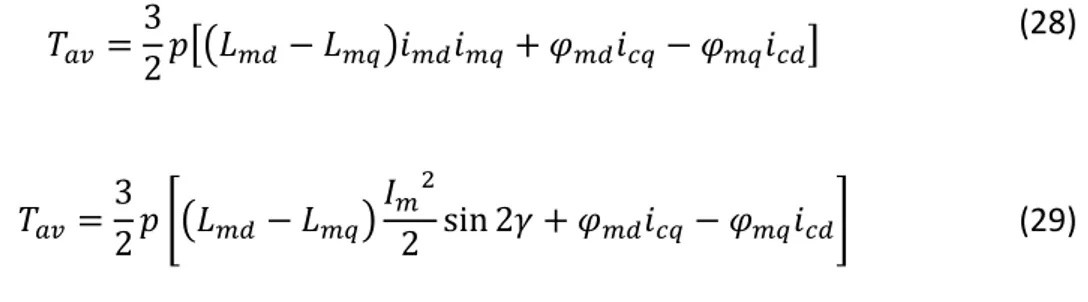
In this expressions the dependence on the inductance and on the magnetization current term is highlighted. Replacing the current values and as a function of the respective components that represent the aspects of magnetization and losses in the ferromagnetic core, it is obtained the following expression of the torque,
[( ) ]
*( ) +
(28)
(29)
The iron losses have two effects: firstly they reduce the output power and therefore the torque, and second they increase the angle of current, therefore the angle that corresponds to the production of the maximum torque per ampere.
In recent years, thanks to the development of power electronics and control systems, the Synchronous Reluctance motor has been able to leave the need for a cage-based start-up structure, allowing the possibility of a suitable design that would allow a high level of salience and a high level of performance. The possibilities of optimization in terms of rotor design to create a difference of reluctance between the axes are many and present different degrees of freedom. In the following it will be illustrated the classifications of the different types of rotor and the main parameters in which to act in order to obtain an adequate torque and a reduced torque ripple that is translated in terms of the difference between the inductances and the relationship between them.
Fig. 2.4 Example of equivalent circuits in rotor reference frame including iron losses, d-axis circuit (left) and q-axis circuit (right)
18
2.2 Design features
2.2.1 Classification based on the rotor design
High anisotropy reluctance synchronous motors can have mainly two configurations, which are the transverse lamination (TLA) and axial lamination (ALA). The salient poles configuration similar to that of a switched reluctance motor has been gradually abandoned in the studies as this presented the problems of noise and vibrations production. As regards the TLA and ALA rotors, both types channel the flux through flux barriers and flux segments. The former are made of magnetically insulating material, and these in a TLA rotor usually consist of air making holes without the addition of other material, while the flux segments are made of iron.
In the case of the transversal laminated type (TLA), the rotor is composed of a pack of perforated laminations. The mechanical strength of the rotor is obtained thanks to thin magnetic bridges whose thickness is mechanically sized. These are arranged in the air gap in a tangential and radial way to guarantee a greater mechanical strength. The thickness of bridges typically varies from a few tenths of a millimeter for the smallest machine to a few millimeters for the largest machines. An advantage of this configuration lies in being able to optimally size the permeances of the individual flux barriers in order to optimize the rotor structure, making the distribution of the magnetic field in quadrature as sinusoidal as possible, thus achieving a low torque ripple.
A disadvantage, on the other hand, lies in not being able to confer distributed anisotropy, that is, the flux barriers cannot tend to infinity, which is why the salience ratio will be less than an ALA rotor.
19
Fig. 2.5 Example of cross-section of TLA rotor [66]
Fig. 2.6 Example of TLA rotor
The axial laminated SynRM (ALA) is obtained by assembling magnetic laminations interposed to amagnetic insulating sheets, which are subsequently bent and arranged axially to the rotor shaft. Their arrangement allows them to perform the dual function of flux barrier and rotor cage. To support the structure, non-magnetic spacers are used and the motor shaft is also non-magnetic. An advantage of this configuration lies in being able to obtain high salience factors leading to a better performance and a greater power factor. However, there are also drawbacks due to the high level of surface saturation of the rotor laminations, due to the stator slots, and to the high losses in the rotor iron caused by the flux harmonics in the magnetic plates of the stator teeth. However the ALA motor has a slight advantage in terms of torque density compared to a TLA, which however from the constructive point of view is more
20
convenient since in terms of production the ALA rotor requires a more complex process since a solid magnetic material is required to maintain a constant space between segments. For this reason the TLA rotor is the most adopted for the construction of a Synchronous Reluctance motor. Another reason of disadvantage in using an ALA type rotor lies in the fact that it is not possible to perform the skewing technique, much used in order to reduce torque oscillations, due to its mechanical complexity.
Fig. 2.7 Example of section of ALA rotor [66]
Fig. 2.8 Example of ALA rotor
2.2.2 Flux barriers shape
As mentioned, the TLA rotor is the most used type for Synchronous Reluctance motors, and in almost all of the articles that were found in literature this type of structure is analyzed. The shape of the barriers takes on particular importance, which is chosen
21
according to the best distribution of the flux obtained. To obtain the best saliency ratio, the direct flux of the direct axis must be maximized and that of the axis with higher reluctance must be reduce as much as possible. The two main forms are straight-line barriers and arc-shaped barriers. However, it has been shown how the adoption of flux barriers with the shape that follows the path of the field lines produced by the stator winding that would be obtained in a rotor without flux barriers is the best compromise to obtain high performances. The flux along the direct axis to be maximized must be supported by flux segments that follow its path, while on the "q" axis the shape of the flux barriers must be perpendicular to the flux lines. This form of the barriers was adopted as a starting point in articles where the objective was to obtain a motor that would optimize torque density and minimize joule and iron losses. In fact, the results achieved were those of obtaining a considerable increase in the saliency ratio, obtained thanks to a considerable decrease in the q-axis inductance, and an improvement as regards the torque ripple and the power factor with respect to motors that use arc-shaped barriers. As regards the number of flux barriers to be adopted to improve performance, this value must be coordinated with a suitable number of stator slots. Usually the parameters regarding the stator of a SynRM are fixed since the comparisons are carried out using the same stator belonging to an Induction motor or to a Synchronous Permanent Magnets motor for reasons of simplicity, even constructive, therefore operating only on the choice of adequate rotor design.
The number of flux barriers per pole is usually greater than four, as this has proved to be the best choice in terms of high developed torque and reduced torque ripple. A further increase in flux barriers did not seem to bring significant improvements. However, there are also applications that have obtained a motor with a high torque density using a number of stator slots equal to 36 and a number of flux barriers per pole equal to 3.
22
Fig. 2.9 Example of different barrier's shape
The specific power and the torque density can be further improved by using or not the last flux segment on the rotor periphery. This absence is called cut-off for the TLA rotor. The absence of this segment involves, first of all, a decrease in the weight of the rotor material, thus involving a specific increase in power with respect to the configuration in which this segment is used. The decrease in torque fluctuation is significant if the last segment is cut, reaching percentages of about 42% less of ripple [7].
Fig. 2.10 Example of TLA rotor with cut-off (a) and without cut-off (b) [8]
2.2.3 Flux barriers geometry
The position of the flux barriers and the suitable asymmetry of the rotor are chosen in such a way as to reduce the torque ripple, mainly due to the slots harmonics. The
23
configurations with different flux barriers per pole allow to have a high rotor saliency which translates into a high average torque.
The geometry of the barriers is an essential aspect since it is what allows to obtain the anisotropy of the rotor. The saliency ratio is the most important parameter as regards the achievement of a high power factor, high torque/current ratio, and a wide constant power speed range. All these aspects must be taken into consideration in order to obtain a machine that has a reduced torque ripple or at least within acceptable limits (this assumes particular importance for those applications such as traction where having a low torque ripple avoids noise or vibrations), a high efficiency over a wide speed range, and that resists the mechanical stresses to which the motor is subjected, and also has an adequate value of torque density and power.
It has been verified how the torque ripple can be reduced by different techniques: rotor inclination (skewing technique), suitable choice of number of flux barriers with respect to the number of stator slots, and optimization of the choice of the geometry of these barriers. Each barrier is defined by different variables: shape, thickness, angular position at the air gap, length and position with respect to the depth of the curvature.
The thickness of the flux barriers has an impact on the value of the saliency ratio and on the developed torque. The maximum and average torque value increases as the thickness of the flux barriers increases, but torque ripples also increase. This happens due to the fact that the reluctance of axis "q" increases more rapidly as the thickness of the barriers increases, since the part of air present increases, but saturation in the stator teeth and tangential ribs causes the air flux to suffer large distribution variations assuming an irregular trend. However, this irregular pattern is a function of the amplitude of the current vector, so it would be enough to reduce the current to reduce the saturation and therefore the torque ripple. Flux barriers can take on different thicknesses from each other, even if the configurations that have the same thickness are usually adopted so that the flux through these zones follows a constant path. In this regard it can be said that the flux in quadrature for each segment can be divided into two components: a circulation flux; a flux that crosses the rotor (limited by air barriers).
24
The torque ripple is mainly caused by the interaction between stator teeth and the rotor barriers which causes a discontinuous change in reluctance, this is caused by the relative position between the stator teeths and the outer edges of the flux barriers. As regards the relative position between the edges of the barriers and the stator teeth, the configuration in which the edges match the teeths is usually used. However, it has been noted that by changing this relative position, in which the center of the flux barrier corresponds to the center between the teeth and the slots and obtaining an asymmetrical configuration, an improvement in the torque has been obtained. However, this change has no effect on the torque developed as it is not seen by the inductances.
In order to reduce torque ripple in [9] two types of asymmetric rotor configurations are proposed where the objective was to attenuate the amplitude or totally eliminate some harmonic torque components thus to have the lower undulating trend possible. The study shows how a configuration can be used with two different types of laminations in order to reduce torque oscillation. Another method may consist in using two different geometries for the flux barriers for adjacent poles, using alternatively from pole to pole barriers of different shape and geometry. This configuration is called "Machaon rotor". This configuration belongs to the category of flux barriers with an asymmetrical shape which leads to compensation of the torque harmonics between adjacent poles.
25
The aspect relative to the position of the barriers has been highlighted in some studies and the geometry with an I-shaped barrier, therefore not excavated and with ∆x equal to zero, and the others with a U shape turned out to be the one that best resists to mechanical stresses due to centrifugal forces due to the lower amount of iron in the peripheral area of the laminations. Furthermore, this geometry reduces the moment of inertia, and having a less degree of freedom in design results to be the best alternative together with the arc-shaped barriers, also in terms of optimization time. Furthermore, the I2U type geometry was found to be suitable for the insertion of magnets to improve the power factor and extend the speed range with constant power, in which case it move to a Synchronous Reluctance machine assisted by permanent magnets (PMASynRM). In the published studies this rotor geometry was found in applications where the rotor design had to be optimized for high speed drives, where a better distribution of mechanical stresses in tangential ribs is required in order to have a high mechanical strength.
Fig. 2.12 3U and I2U rotor example [7]
The number of barriers to be used, the relative thicknesses and the inclination angles between the different barriers are defined as microscopic parameters and it is difficult to characterize entirely the anisotropic structure of the rotor by means of these parameters. These aspects can be linked together by the preliminary choice of the so-called insulation ratio, a parameter that links the flux barriers with that of the flux segments. This parameter is given by the ratio between the sum of the thicknesses of
26
the flux segments and the sum of the thicknesses of the flux barriers, and is defined as a macroscopic parameter.
A motor with a zero insulation ratio indicates a fully laminated rotor, without holes, and therefore with a saliency ratio equal to zero. This parameter for the most part of studies aimed at obtaining a design suitable for a Reluctance motor and is assumed to be around 0.4-0.6, a value that provides a higher maximum torque value. It is also possible to make separate assessments regarding the insulation ratio for the two axes, and an increase in the ratio along the "q" axis causes a decrease in .
So in conclusion the aspect related to the geometry of the flux barriers, which means the choice of number, thickness, shape, position has an important impact on those that are the performances required by the motor, since a correct choice allows to reduce the ripple, improve the saliency ratio and therefore the power factor, and increase the difference between the inductances of the two axes and therefore increase the average torque developed by the motor.
2.2.4 Tangential and radial ribs
Particularly important is the optimization of the dimensions of radial and tangential magnetic ribs, which are the only elements that hold together the different flux segments of a TLA rotor. Sizing these elements correctly is very important both from the mechanically and electromagnetically point of view. A correct choice of the dimensions allows to obtain a high resistivity to the mechanical stresses to which the rotor is subjected, an aspect that assumes an important relevance in high speed applications. As far as their electromagnetic function is concerned, they act as magnetic short circuits, thus increasing the leakage and the quadrature inductances. Therefore the thickness must be as small as possible to limit these last two quantities but at the same time it must assume sufficiently high values to guarantee the mechanical strength and be robust to withstand the mechanical stresses. Several studies show the variation of the inductance parameters as the dimensions the bridges vary. The reduction in thickness leads to an increase in the saliency ratio and the
27
difference between the inductances, and therefore produce an increase in the torque and an improvement in the power factor, which is more influenced by this variation in thickness, since it depends on the saliency ratio and this ratio varies more significantly than the difference between the inductances and therefore the average torque. The radial magnetic bridges are very important with regard to the strength against the centrifugal forces of the rotor especially for Synchronous Reluctance motors used for high speed applications. They are rotor-reinforced structures that are subject to saturation, thus allowing the different segments to have different magnetic potential. The simultaneous effect of both bridges shows how the variation in thickness of the radial ones has a greater impact on the performance of the motor, in terms of the saliency ratio and torque produced. So when the motor has to be designed to reach high speeds and therefore the mechanical specifications are more stringent it is better to reduce the size of the radial ribs rather than the tangential ones. So as investigated by some authors in literature the solutions to increase the maximum speed of the SynRM are: change the thickness values of tangential and radial ribs, fill the barriers with non-magnetic materials, increasing the number of ribs.
28 2.2.5 Influence of the air-gap
The air-gap length has a major influence on the d-axis inductance, while on the inductance it can be considered negligible as an effect. Usually the thickness of the air gap must comply with restrictions due to mechanical aspects, so to increase the saliency and have an effect on the inductances must try to be reduced as much as possible. However, this increase in torque must pay the price of also increasing torque ripple and iron losses due to the simultaneous increase of the Cartier factor.
2.2.6 Influence of the number of poles
Also the number of poles has an influence on the performance of the motor in particular on the electromagnetic and mechanical characteristics, since the saliency ratio and the developed torque depend on this parameter. First of all, a low number of poles are preferable as it has a simple design but would have the disadvantage of increasing the pole pitch with a consequent increase in coil ends which would therefore result in a greater complexity of construction and a greater quantity of copper material to be used with consequent increase in thermal problems. Furthermore, since the average torque developed depends on the number of poles, a low number of poles would result in a lower torque developed and greater ripple. Therefore for the design of a high performance Synchronous Reluctance motor it is usually preferable to adopt a number of poles greater than two. On the other hand the increase in the use of the number of poles is limited by the geometry of the rotor, in particular by the external diameter, in which for machines that require compactness this number is limited and usually a number greater than six is not used.
As mentioned before, the thickness of the magnetic ribs is very important as it ensures the mechanical strength of the rotor, which aspect becomes relevant when the speed at which the motor must operate increases. However, as we have seen, a compromise must be found as the increase in thickness ensures a better mechanical strength but worsens torque development. This decrease in the torque developed is proportional to the square of the number of poles as well as to the thickness of the bridges. Therefore
29
for high performance motors with a higher number of poles it is necessary to find a suitable dimensioning of these structures.
As mentioned before, the q-axis flux is composed by circulating flux across the segments ends and the stator teeth as well as the flux that is flowing through the segments and barriers and therefore the "q" axis inductance can be considered as it is given by the sum of two terms: an which represents the airflow circulation flux;
and the other relating to the flux passing through segments and air. In [10] it is
shown as the ratio ⁄ is independent from the number of pole pairs but decrease as the number of flux barriers per poles increase,
(30)
On the contrary the ratio does not depend from the number of flux barriers per pole but from the number of pole pairs as it is illustrated by this relationship:
(31)
where g is the thickness of air gap; is the total thickness of the flux segments of a pole in the direction of the q-axis. The efficiency of the motor is also influenced by the choice of the number of poles. With regard to the losses a smaller number of poles would allow to reach a certain speed with a lower frequency compared to a motor with a greater number of poles, and this would have an effect in the losses in the ferromagnetic core which depend on the power supply frequency. On the other hand, as mentioned a smaller number of poles would involve longer ends windings, with consequent increase in joule losses. A higher number of poles lead to a better torque/current ratio and better mechanical strength, as well as a reduction in torque ripple [10]. Moreover an higher number of poles can contain the magnetizing current needed especially at starting conditions.
30
2.3 Control and operating domain aspects
2.3.1 Operating limit points
From the control point of view there are different strategies that can be pursued. One of the many is based on the fact that the inductance on the "d" axis electrical circuit is much greater than that on the "q" axis which implies that the same relation also applies to the respective time constants. Moreover the low inertia of this motor and the weight of the small rotor contribute significantly to speed up the control and the time taken to reverse the speed. There are different strategies for implementing a closed-loop control of a Synchronous Reluctance motor and usually these techniques use field-oriented control (Field Oriented Control, FOC) since this technique uses the park transform to decouple the components. Control strategies are mainly classified into:
- Control at constant current ; - Fast torque response control;
- Maximum torque per ampere control; - Maximum power factor control;
In variable speed drives for motor control the technique used is to vary the parameters of voltage and frequency of the stator power supply.
The voltages and currents that can be applied to the motor must remain within specified limits that usually coincide with either the nominal values of the machine or those of the power supply, and usually these two quantities are the same. The determination of the corresponding operating limits of the motor are determined by considering normal steady-state operation, and considering the ideal model in the absence of saturation and neglecting the iron losses. The voltage is increased almost linearly with the speed up to a certain speed , called the base speed of the motor, where the voltage reaches the maximum value compatible with that of the inverter voltage. Below this speed the module of the stator flux vector is kept constant, and if the speed has to be increased beyond the base speed the value of this module have to be decreased. The speed area up to is called a constant torque zone. Beyond this
31
speed value, the motor operates in the constant power zone, where the torque limit value and the stator flux vector module decrease as the speed increases, in fact this zone is also called the “field weakening zone”. To satisfy the limitations the current of each stator phase must have amplitude in RMS value not higher than the nominal value , value beyond which the joule losses produced in the stator circuit would bring the operating temperature of this component to take unacceptable values from the point of view of thermal sustainability. In summary, the operating limit for the operating current must respect the following relationship in the d-q reference frame:
(32)
the latter in the plane of the "d" and "q" axes currents is represented by a circle with center in the origin of the axes.
Fig. 2.14 Current limit circle, voltage limit ellipse and MTPA trajectory in the d-q currents plane [67]
This limit also applies to the stator power supply voltage which must remain within its nominal value, this depends on the insulation selection criteria and on the
32
electromagnetic sizing of the motor. The nameplate data usually refers to the line to line RMS voltage. The following applies to voltages:
(33)
Wanting to represent this limit in the same diagram used for the circle of the current limit, replacing the two voltages of axis "d" and axis "q" with the expressions relating to the two voltages in steady state, and neglecting the resistive voltage drop, which is a good approximation for high speeds it is obtained the following:
( ) ( )
(34)
which represents an ellipse with center in the origin in the plane of the currents and , since synchronous reluctance motors have zero short-circuit current, and which radius decreases with the increasing of the speed.
Fig. 2.14 Example of operating characteristics of SynRM motor [67]
These currents and voltages limits in turn produce torque and speed limits. From the expression of the torque, by expliciting the current , it is obtained branches of hyperbole called "iso-torque" which express the relationship between the two axes
33
currents along the plane at a constant value of the torque. Considering that the operation is a motor mode and therefore the torque is positive and that the reference system chosen for the axes "d" and "q" means that is greater than such branches of hyperbola are located in the first quadrant, and have as horizontal and vertical asymptotes the axes "d" and "q". The point of tangency between the circumference of the current limit, the voltages ellipse and the nominal torque curve represents the operation of the motor at the base speed, whose expression is given by:
√( ) ( )
(35)
Up to this speed, the control strategy most used to achieve high performance is the “Maximum torque per ampere” (in the abbreviation MTPA) where a control trajectory is followed along a curve that maximizes the ratio between torque and current amplitude, and therefore the efficiency, since using this control technique for a given load the losses in the copper are minimized. The operation of the motor at a given working speed, in compliance with the voltage and current limits, corresponds to an internal working point both at the current and voltage limits which corresponds to that working speed. For low speed operation the voltage limit is very wide and the current limit is more restrictive. In this case it is therefore possible to operate in the MTPA location until such a place is inside the voltage limit, which corresponds to the nominal speed. To minimize the stator current with respect to a given load torque it is necessary to choose a suitable angle for the current vector which can be given by:
( ) (36)
For the control in the constant torque zone, the following relationship is adopted for the MTPA control strategy:
( )
(37)
34 ( )
(38)
So if the derivative of (11) is made the angle that allows minimizing the module of the stator current with respect to the torque corresponds to γ = 45 ° and the two components of current are thus linked by the relationship: .
Fig. 2.15 Different torque values as function of stator current amplitude
The point corresponding to the maximum developable torque is at the intersection of the line of the MTPA and the limit circle for the current, which corresponds to the nominal operating point of the motor. The current components at this point are:
√ (39) However, it has been analyzed that considering the saturation effects, which is the dependence of the flux value on the respective current component, influences the ideal motor model and the relationship between the torque and the current. Due to saturation an excessive current increase causes a decrease in the flux and therefore a considerable decrease in the inductance in the "d" axis, which at a given current angle corresponding to the theoretical previous angle of 45 °, drastically decreases the torque.
35
This decrease must be activated by increasing the current angle to obtain the original torque value, and shows how the influence of saturation has an important impact on what is the MTPA control strategy [11]. The reason is that the electromagnetic torque is generated by the interaction between the flux vector and the magnetization current . The modulus of the axis flux vector “d” does not change linearly with the magnetization current component . Therefore it is necessary to use a correct
value for the module of this component in order to not saturate the iron part, which along the d-axis is predominant. Therefore for this reason the current angle is checked to guarantee an adequate flux value, and increasing it also increases the magnetization component along the axis q, the , thus favoring the development of torque.
Even the iron losses have an influence on the search for the optimal angle of current to guarantee the achievement of the torque/ampere performance. This effect requires a further increase in the angle to reduce the flux value and the losses in the magnetic core. Another aspect to take into consideration for the control is that related to the dependence between the iron losses and the supply frequency. If the frequency increases, the current flowing in the equivalent circuit along the resistance will be greater, and therefore the losses will increase, therefore the choice of an angle suitable for this effect must be taken into consideration, and is an aspect that becomes relevant as the speed increases. Instead, it has been seen how the effect of magnetic coupling between the two axes does not affect the choice of the current angle for maximum torque production compared to the ideal machine model. The maximum torque obtainable for a given current is always approximately the same as a 45° current angle. For machines with high losses in the core the saturation effect can be neglected since it is already used with a high value of the current angle which makes the saturation negligible.
36
2.4 Different control strategies
2.4.1 Maximum power factor control strategy
This control strategy aims to maximize the power factor, and together with the MTPA it is classified as one of the most used controls that operate using a constant current angle, always in the constant torque operating area.
For the ideal model this method considers the angle in which the maximum power factor is reached, given by √ ; this method leads to the ideal machine to minimize the inverter's kVA size.
The iron losses as seen make the model of the machine and the control more complex, and in [8] the expression of the internal power factor is introduced in which the dependence between the magnetizing inductances and currents components is shown. In fact, the magnetization angle ε, which is the angle formed by the current magnetization vector with the d axis, does not coincide with that corresponding to the stator current vector γ, an effect due precisely to the losses in the ferromagnetic core. The internal power factor assumes the following expression:
√ ( ) √( ) (( ) ) (( ) ) (40) (41)
The angle of current in which the power factor is maximized is greater than the current angle relative to the production of the maximum torque/current ratio, the difference between the angles decreases as the load increases.
37
The ideal operating angle for the maximum power factor control is close to the value found considering the model with saturation and iron losses, but the power factor value is increased in the latter case. As well as in [12] the behavior of the motor under overload conditions was tested by showing how the internal power factor decreases as the stator current increases.
2.4.2 Maximum Rate of Change of Torque Control
This control strategy aims to always obtain the maximum instantaneous torque derivative from the machine. In essence, the motor is made to work along the path that maximizes the maximum derivative of the torque dT/dt at any instant of time. For the ideal machine the current angle that corresponds to this control is:
√ . (42)
In [13] it is highlighted how the optimal angle of the magnetizing current does not vary much depending on the motor power range, but higher torque levels lead to higher values of the derivative of the torque. Furthermore the saturation in this case does not have a significant effect on the behavior of the motor in terms of choosing the optimal current angle, which is more or less the same in both machine modeling.
2.4.3 Field Weakening Control
For speeds greater than the base speed the voltage reaches its maximum value compatible with that supplied by the inverter. Wanting to increase the speed, therefore, it is necessary to weaken the field which results in a reduction of the modulus of the stator flux vector and therefore of the torque, which follows a trend inversely proportional to the speed. In the limit plane of the currents as mentioned before, the ellipse that represents the limit of the voltages narrows with increasing
38
speed and therefore becomes of primary importance in the choice of the trajectory to be followed in the control. The equation that expresses this limit and which shows the dependence on speed is the following:
( ) ( ) (43)
further simplifying and performing some steps it is obtained:
( ) ( )
( )
(44)
which leads to the expression in ideal conditions, neglecting the effects of saturation and the iron losses, of the angle of current in the field weakening area:
√
( )
( )
(45)
Using this equation, the angle between the current vector and the "d" axis to be used at a given speed is determined, and consequently generate the necessary current components of reference for the constant power zone.
The non-linear magnetic model of the synchronous reluctance motor can use the same approach for field weakening. However, also in this case there is a difference from the angle used in ideal conditions, in fact these angles are much greater and need to be estimated, undergoing the influence of the variations of the equivalent resistance used to model the losses in the iron and of the "d" axis inductance.
The two most commonly used vector control strategies for controlling synchronous reluctance motors are the FOC (Field Oriented Control) and DTC (Direct Torque Control) controls. These methods have proven to be the best alternative in terms of performance improvements to achieve maximum uptime at optimal torque, with high efficiency, a good power factor and low losses. They also give fast torque transients. The FOC consists in controlling the two stator currents in a completely decoupled manner, as happens for a DC motor, in which one component of the stator current acts
![Fig. 2.14 Current limit circle, voltage limit ellipse and MTPA trajectory in the d-q currents plane [67]](https://thumb-eu.123doks.com/thumbv2/123dokorg/7523064.106247/38.892.214.534.678.957/current-limit-circle-voltage-limit-ellipse-trajectory-currents.webp)
![Fig. 2.16 Example of DTC structure [68]](https://thumb-eu.123doks.com/thumbv2/123dokorg/7523064.106247/47.892.148.697.109.363/fig-example-of-dtc-structure.webp)

![Fig. 3.2 Parameter comparison between IM and SynRM [17]](https://thumb-eu.123doks.com/thumbv2/123dokorg/7523064.106247/54.892.170.660.877.1065/fig-parameter-comparison-im-synrm.webp)
![Fig. 3.3 Parameters of SynRM for air-conditioning compressor [18]](https://thumb-eu.123doks.com/thumbv2/123dokorg/7523064.106247/55.892.213.492.565.842/fig-parameters-synrm-air-conditioning-compressor.webp)