Autore:
Vincenzo Pellegrini ____________________
Relatore:
Prof. Marco Luise ________________________
Fast Memory-Based Processing
in Software-Defined Radios
Corso di Dottorato di Ricerca in
Ingegneria dell’Informazione
Copyright c° Vincenzo Pellegrini, 2012
Manuscript received February 28, 2012 Accepted March 28, 2012
Sommario
Negli ultimi anni le Software Defined Radio sono state un argomento di ricerca di primo piano nell’ambito dei sistemi di trasmissione radio. Molti e variegati paradigmi implementativi sono stati concepiti e proposti, con soluzioni capaci di spaziare da sistemi basati su Field Programmable Gate Array (FPGA) a implementazioni ot-tenute mediante un singolo General Purpose Processor (GPP) passando per dispositivi caratterizzati dalla presenza computazionalmente preponderante di un Digital Signal Processor (DSP) o da architetture miste. Tali soluzioni rappresentano punti di equilib-rio diversi dell’inevitabile compromesso tra flessibilit`a e capacit`a computazionale del sistema di trasmissione implementato, comprimendo in qualche modo l’aspirazione ad un sistema radio universale propria del concetto originario dell’SDR. A questo riguardo, le soluzioni SDR basate su GPP rappresentano il modello
implementa-tivo maggiormente desiderabile in quanto costituiscono l’alternativa pi`u flessibile ed
economica tra tutte le tipologie di SDR. Ci`o nonostante, la scarsa capacit`a
com-putazionale ha sempre limitato l’adozione di questi sistemi in scenari produttivi di vasta scala. Se convenientemente applicati entro il contesto di sviluppo SDR, concetti classici noti in informatica sotto la denominazione collettiva di space/time trade-off possono essere di enorme aiuto quando si cerchi di mitigare un simile problema. Traendo ispirazione da detti concetti, nonch`e estendendoli ed applicandoli all’abito dell’SDR, questa tesi sviluppa e presenta una tecnica di programmazione specifica per software radio chiamata Memory Acceleration (MA) che, mediante un uso estensivo delle risorse di memoria disponibili a bordo di un tipico sistema di calcolo general purpose, pu`o fornire alle SDR convenzionali basate su GPP fattori di accelerazione sostanziali (circa un ordine di grandezza) senza ridurne la peculiare flessibilit`a. Alcune rilevanti implementazioni di sistemi SDR capaci di lavorare in tempo reale su proces-sori GPP consumer-grade realizzate in tecnica MA sono descritte in dettaglio entro questo lavoro di tesi e fornite come prova della reale efficacia del concetto proposto.
Abstract
In recent years Software Defined Radios (SDRs) have been quite a hot topic in wireless systems research. Many implementation paradigms were conceived and proposed ranging from Field Programmable Gate Array (FPGA) implementations to single General Purpose Processor (GPP) systems while also including mixed architecture and Digital Signal Processor (DSP) based devices. All such choices trade-off system flexibility for computing power, compressing, to some extent, the quest for an uni-versal radio system which is inherent to the original SDR concept. In this respect, GPP-based solutions represent the most desirable implementation model as they are the most flexible and cost effective among all types of SDRs. Still, the scarcity of com-putational power on general purpose CPUs has always constrained their wide adoption in production environments. If conveniently applied within an SDR context, classical concepts known in computer science as space/time trade-offs can be extremely helpful when trying to mitigate this problem. Inspired by and building on those concepts, this thesis presents a novel SDR implementation technique called Memory Acceleration (MA) that makes extensive use of the memory resources available on a general purpose computing system, in order to accelerate signal computation. Actually, MA can provide substantial (about one order of magnitude) acceleration factors when applied to conventional SDRs without reducing their peculiar flexibility. Notable real-time, consumer-grade GPP SDR implementations that were obtained while developing the MA SDR programming technique are described in detail within this work and pro-vided as factual proofs of the MA concept effectiveness. Opportunity for extending the MA approach to the entire radio system, thus implementing what we call a Memory Based Software Defined Radio (MB-SDR) is as well considered and discussed.
Acknowledgments
Once reached the incipit of this PhD thesis, I really feel I have to thank a bunch of people.
My advisor Professor Marco Luise for his guidance, for the perspective he was continuatively able to provide on exciting research and development opportunities throughout the PhD program and, particularly, for that day, some years ago, in which he spoke to my ears the words “Software Defined Radio” for the first time. My co-advisor Filippo Giannetti for the invaluable insight he always provided into a wide variety of radio transmission issues as well as for having shared with me the emotion of “teaching the wonders of the radio”. My colleague and friend Mario di Dio, for the daily (and nigthly) effort and time spent together in chasing and improving the performance of state of the art SDRs. Dr. Giacomo Bacci of the Pisa University DSP for Communication Lab, for his constant, precious and always gentle help.
Elisabetta, Bernardo, Monica and Giovanni, without whose love, endurance and support, none of the steps composing this research path could have ever been moved forward.
Contents
List of figures ix
List of tables xi
List of acronyms xiii
List of symbols and operators xvii
Introduction 1
Motivations for a “different” SDR . . . 1
Principal issues and challenges . . . 3
Thesis outline . . . 5
1 SDR today: the state of the art 7 1.1 “Historical” notes . . . 7
1.2 Academic and amateur research . . . 10
1.3 Commercial systems . . . 11
1.4 Industrial research . . . 13
2 The memory option: MA research activity 17 2.1 Description of the Memory Acceleration design rule . . . 18
2.1.1 System representation and useful quantities . . . 18
2.1.2 Acceleration design . . . 20
2.1.3 Table aggregation and cache friendliness . . . 23
2.1.4 Recursive Table Aggregation Rule . . . 23
viii CONTENTS
2.2 Application and performance metrics of MA . . . 28
2.2.1 MA compatibility with different acceleration techniques . . . . 28
2.2.2 Performance evaluation . . . 28
2.3 A case study: the DVB-T Viterbi decoder . . . 30
2.3.1 MA design for the Viterbi decoder . . . 30
2.4 Other memory-accelerated algorithms . . . 33
3 MA application to real-world systems 39 3.1 The ETSI DVB-T transmission standard, some PHY-layer notes . . . 39
3.1.1 Analysis of ETSI DVB-T functional blocks . . . 40
3.2 Soft-DVB, a software defined DVB-T modulator . . . 42
3.3 Soft-SFN, a software-defined Single Frequency Network . . . 47
3.4 SR-DVB, a software defined DVB-T demodulator . . . 50
3.5 Second generation DVB systems, improvements and evolutions . . . . 51
3.6 Soft-DVB2, a software defined DVB-T2 modulator . . . 54
4 MB-SDR, opportunities of a full-memory approach 59 5 Conclusions and perspectives 63 5.1 Development perspectives . . . 64
5.2 Research perspectives . . . 64
Bibliography 67
List of Figures
1.1 LYRtech Virtex-4 FPGA SDR Development Platform . . . 9
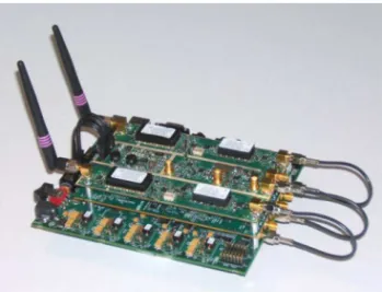
1.2 Sundance SMT 8146 SDR Development Platform . . . 9
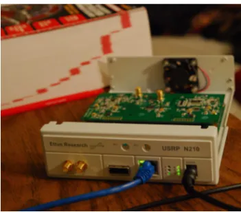
1.3 USRP n210, the highest profile USRP currently available from Ettus Research . . . 12
1.4 HPSDR hardware peripheral . . . 12
1.5 Selex-Elsag Swave Vehicular SDR . . . 13
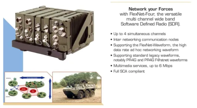
1.6 Thales FlexNet-Four Vehicular SDR . . . 14
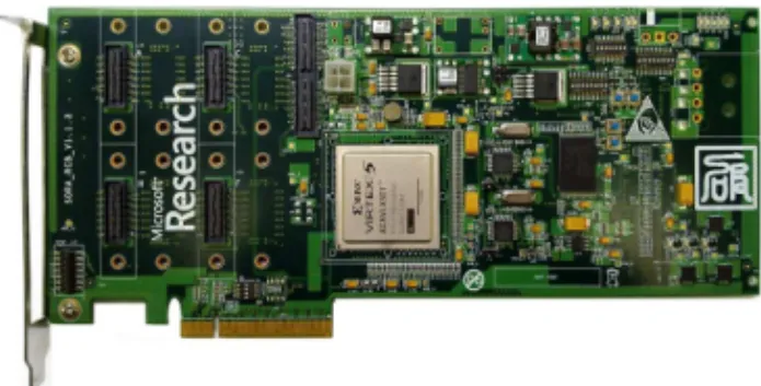
1.7 Microsoft Research Asia Sora PCIe SDR Board . . . 15
1.8 Microsoft Research Asia Sora PCIe SDR Board operating within a standard PC . . . 15
2.1 Possible system representations: black box and web of constituent blocks 18 2.2 Table boundary after one step, released block is peripheral . . . 20
2.3 Computational cost weighted functional block representation. Blocks 1 and 4 are peripheral . . . 20
2.4 Table boundary after one step, released block is peripheral . . . 24
2.5 Atomicity limit reached . . . 24
2.6 Example of released block (FB5) being non-peripheral . . . 25
2.7 Schematic representation of MA Recursive Table Aggregation Rule . . 26
2.8 Multiple processing cores, their dedicated caches and table loading from RAM to the core-dedicated cache . . . 29
2.9 Classical functional block decomposition of the Viterbi Decoder. All displayed functional blocks are implemented through pure computation 32 2.10 Computation-only implementation of our Viterbi decoder . . . 36 2.11 Memory-accelerated Viterbi decoder as returned by RTAR. f(...)
x LIST OF FIGURES
2.12 A very basic MA application: segmentation of a computationally-implemented local oscillator a), into a finite set of tabled complex
oscillations b) . . . 38
3.1 Functional block scheme for the standard ETSI DVB-T transmitter . . 40
3.2 Spectrum of the digital signal at the output of the Soft-DVB SDR . . 43
3.3 Output of the Access Media STB1230 test receiver fed by the Soft-DVB
transmitted signal . . . 44
3.4 Soft-DVB SDR over the Atom embedded-class CPU. Development setup 45
3.5 Soft-DVB SDR over the Atom embedded-class CPU. Performance Figures 46
3.6 Classical MFN Vs SFN configuration. Courtesy of Enensys . . . 47
3.7 Soft-SFN test setup architecture . . . 49
3.8 Soft-SFN test setup. A still from the demonstration video . . . 49
3.9 Output of the mplayer Linux media player being fed by the MPEG TS
received with SR-DVB. . . 51
3.10 Analysis of the demodulated MPEG Transport Stream . . . 52
3.11 The ETSI DVB-T2 broadcasting chain. Source: wikipedia.org . . . 54
3.12 Soft-DVB2 SDR over the Intel E8400 CPU. Performance Figures . . . 56
3.13 The SHARP TU-T2 set-top-box used as a test receiver . . . 57
3.14 Soft-DVB2 SDR at work. Output of the SHARP TU-T2 test receiver
List of Tables
List of Acronyms
ADC Analogue to Digital Converter
ATSC Advanced Television Systems Committee
AWGN Additive White Gaussian Noise
BCH Bose Chaudhuri Hocquenghem
BER Bit Error Rate
COFDM Coded OFDM
CORBA Common Object Request Broker Architecture
CPU Central Processor Unit
DAB Digital Audio Broadcasting
DAC Digital to Analogue Converter
DMT Discrete MultiTone
DRM Digital Radio Mondiale
DSP Digital Signal Processing
DSPCOLA DSP for Communication Lab
DVB-T Digital Video Broadcasting - Terrestrial version
ESSOR European Secure SOftware defined Radio
ETSI European Telecommunication Standards Institute
FEC Forward Error Correction
FFT Fast Fourier Transform
FFTW Fastest Fourier Transform in the West
FM Frequency Modulation
GF Galois Field
xiv LIST OF ACRONYMS
GRC GNURadio Companion
GSM Global System for Mobile communications
HDTV High Definition TeleVision
HW Hardware
IEEE Institute of Electrical and Electronics Engineers
IFFT Inverse Fast Fourier Transform
IP Internet Protocol
JTRS Joint Tactical Radio Systems
LDPC Low Density Parity Check
LFSR Linear Feedback Shift Register
LOS Line of Sight
LUT Look-Up Table
MA Memory Acceleration
MB-SDR Memory-Based Software Defined Radio
MFN Multiple Frequency Network
MIMO Multiple Input Multiple Output
MPEG2 Motion Picture Experts Group2
NO-LOS No Line of Sight
OSSIE Open-Source SCA Implementation - Embedded
PC Personal Computer
PCIe Peripheral Component Interconnect Express
PRBS Pseudo Random Binary Sequence
QEF Quasi Error Free
RF Radio Frequency
RS Reed-Solomon (Codes)
SIMD Single Instruction Multiple Data
SCA Software Communications Architecture
SDH Synchronous Digital Hierarchy
SDR Software Defined Radio
LIST OF ACRONYMS xv
SNR Signal to Noise Ratio
SW Software
TDP Thermal Design Power
TPS Transmission Parameters Signalling
TS Transport Stream
UHF Ultra High Frequency
VHF Very High Frequency
List of Symbols and
Operators
Computation-only implementation of block n fn(...)
Memory-only implementation of block n tn(...)
Number of items within the MIDS l
Cardinality of Alphabet for each item of MIDS A
Cardinality of input space of block fn(...) Cin
Cardinality of output space of block fn(...) Con
Total available computational power W
Computational cost of block fn(...) Wn
Computational cost of subsystem within table boundary WT B
Computational cost of subsystem replaced by table m Wm
Computational cost of subsystem replaced by table m Wm
Computational cost for handling table tm(...) W mm
Total size of available memory M
Total memory footprint of table tm(...) Mm
Data size of items stored in tm(...) Sm
Acceleration factor a
Acceleration efficiency η
Acceleration efficiency of table tm(...) ηm
Introduction
Motivations for a “different” SDR
The field of SDR is slowly attaining its maturity, especially in military and security-related applications [1]. In spite of this, there is still a wide variety of HW platforms to implement an SDR terminal, with no emerging well-established standard solution(s). Amidst this variety, every platform generally adopts its own judicious mixture of (powerful but not so flexible) FPGAs, dedicated DSP processors (less powerful and sufficiently flexible), and/or (easily programmable and flexible but no so powerful) GPPs [2]. Platforms based almost entirely on GPPs are very attractive for research, development and small-scale market deployment, owing to short development time and extremely low development costs [3]. Indeed, they constitute the closest imple-mentation paradigm to the original SDR concept described in J. Mitola’s seminal work [4] back in 1992: the dream of a “universal radio” where all of the needed signal processing is performed directly over a fully reconfigurable computational back-end. If achieved in practice, this fully software architecture could act as an authentic game-changer within the market of radio-frequency (RF) transmission systems, as all pro-duction costs ranging from hardware design to Application Specific Integrated Circuit (ASIC) foundry production would be entirely saved. Reference implementations being written in a high level programming language such as C or C++ could then directly become system pre-production prototypes, or even actual complete products. On the other hand, the drawbacks of such solutions are their limited computational power or, seen from another perspective, their low throughput per Watt when compared to equivalent HW-accelerated (e.g. FPGA-based) implementations [5]. In fact, it has always been a universally accepted assumption that a greater amount of generality and flexibility of the radio system has to be paid with heavy losses on power efficiency, due to the necessary usage of general purpose CPUs. Accordingly, SDR implementations
2 Introduction
up to the present date have simply aimed to replicate the classical HW-implemented signal processing chains into the software realm. Aim of this research is to prove that, by making use of all the resources available on a general purpose computing system (i.e. not only calculus but also memory), it is possible – at least – to substantially reduce the power efficiency gap that exists between SDRs based on general purpose CPUs and HW implementations of the same radio system. Implications of such results include potential for deploying flexible radio technologies on the industrial scale (due to increase of power efficiency up to levels that would make them a practical alternative to HW solutions) as well as do suggest the possibility to implement fully generic, C/C++ definable radio signal processing cores being trivially derived from currently available general purpose CPUs, yet able to deliver very high signal synthesis and demodulation performances.
Introduction 3
Principal issues and challenges
Peculiarities of implementing a real-world software defined radio, especially once the full-software approach has been chosen, make the design and complete development of the radio system substantially different from the traditional work-flow, usually involved in producing conventional, hardware (ASIC) based, radio-communication devices.
Different authors in different contexts adopt different definitions for the rather broad class of what is often referred to as real-time constraints. The term real-time is typically used to indicate both computing time issues and latency issues even if the nature of such constraints is rather heterogeneous. Actually, a practical SDR
implementation has to take into account both needs. An SDR must in fact be
fast enough in processing (modulating and/or demodulating) its informative radio signal to keep-up with the radio frequency (RF) signal rate mandated by the radio communication standard it implements (computational constraint). Also, it must be quick enough in reacting to a stimulus received from the radio frequency channel to comply with external timing requirements imposed by external entities such as (but not limited to) an infrastructured or peer-to-peer network architecture to which the SDR is interfaced (latency constraint). Within this thesis, we will thus respectively distinguish between:
• Computation-yielded real-time constraints
• Architecture-yielded latency constrains
Therefore we will only be using the term real-time with respect to computational power related issues, as these constitute the toughest limit keeping the full-software SDR paradigm from widespread adoption. Timing issues depending on the radio system architecture will be instead referred to as latency issues. It is worth to consider that, as long as an insufficient processing capability slows down the system in all of its tasks due to the typical interdependence of functional blocks, computation yielded real-time constraints can have an impact over latency performance of the radio system while instead the opposite cannot happen, due to the definition we adopt for these two constraint classes. Also, it must be noted that the customary distinction between soft and hard real-time is completely orthogonal to the classification introduced above. In software defined radio, all time constraints are to be considered hard
real-4 Introduction
time bounds as long as missing a single deadline set by the implemented radio-communication standard when processing a single given information unit will (both on the transmit and on the receive chains) have catastrophic effects with respect to the possibility of successfully transmitting that unit and, most likely, some of its contiguous information blocks.
Whenever computational real-time requirements are met, which we must assume as the normal operating condition for any SDR, latency issues might only arise from architectural problems. This fact can have a relevant impact particularly when a full-software implementation paradigm is chosen, which falls right into the main scope of this research. GPP-based systems are conceived and designed around a central computing core (or set of cores) whose operation is regulated by a certain interrupt scheme. Choices taken in implementing such scheme directly yield latency bounds when it comes to make the fully software SDR systems responsive to external stimula acquired through the RF channel (e.g. responding to a transmission request within a certain time which is assigned by some network regulator entity). For these reasons, whenever the SDR system is part of a wider, time-regulated network or when it has to be strictly locked to any sort of external, time-critical event, a real-time kernel must be employed within the host operating system and interrupt as well as hardware-yielded latencies (i.e. timing of buses and hardware interfaces) must be cautiously considered.
Also, given the limited computational power available over GPP platforms, suitable techniques must be implemented within the SDR system in order to maximize its computational efficiency (and thus its throughput-per-watt figures). A proposal being formulated within this context is the main subject of the following chapters of this thesis.
Introduction 5
Thesis outline
The remainder of this thesis is structured as follows.
In Chapter 1, we present the current state of the art of SDR systems with special attention to the full-software option and to its main issues and criticalities. Both the industrial and academic realms are considered.
In Chapter 2, we describe in full detail the proposed Memory Acceleration (MA) SDR programming technique by presenting its logical and quantitative foundations as well as by providing complete examples of its application within real full-software SDR contexts.
In Chapter 3, we describe several complete real-world SDR systems which, along the path of this research, were implemented by resorting to the MA technique, and which we intend as the practical proof of the MA concept.
In Chapter 4, we explore and discuss the idea of extending the memory acceleration design philosophy to the entire software radio system as we imagine and define the concept of a Memory-Based SDR (MB-SDR).
Within the customary conclusions chapter, we discuss implications of the results which were obtained within this research as well as development and research per-spectives that exist within the field of computationally-accelerated software defined radio.
Chapter 1
SDR today:
the state of the art
1.1
“Historical” notes
Probably conceived in 1991, the term and the concept “Software Radio” first appear on the world’s stage in 1992 at the IEEE National Telesystems Conference thanks to Joseph Mitola’s work entitled “The Software Radio” [4] where a universal, fully reconfigurable radio system is imagined as composed by no application-specific subsys-tems and based only upon a general-purpose computational back-end being directly interfaced to the radio medium only through A/D conversion. Since those days, the concept inspired a wide variety of related initiatives in both research and production contexts, which led to a plethora of SDR systems and implementation paradigms. Precisely 20 years, at the time of writing, after Mitola’s seminal work, industry and academia, civilian authorities and the military have all become involved into SDR to some extent and for different reasons. Indeed, the label of early adopters belongs to the United States military whose involvement in SDR technologies dates back to the pioneering days of the SPEAKeasy, phase I and II projects. Such projects consisted in implementing a reconfigurable, multi-standard radio capable of working with ground, naval, airborne and naval forces communication systems (phase I) as well as in obtaining standard-bridging capabilities (i.e. the actual SDR acting as a gateway between heterogeneous RF standards) and in reducing weight and configuration times of former implementations (phase II). The early SPEAKeasy effort extends into nowadays Joint Tactical Radio System: an US military program aiming to obtain
8
SDR today: the state of the art flexible and interoperable communication within a broad set of radio standards. Such system is based on the internationally endorsed Software Communications Architec-ture (SCA): a highly layered software radio architecArchitec-ture designed in order to obtain remarkable cross-platform portability of the implemented radio systems (waveforms in the SCA parlance), which was implemented in a multitude of contexts, including civilian ones. Common Object Request Broker Architecture (CORBA), a special software mechanism allowing pieces of software written in different languages to interoperate is intended as the behind the scenes magic which should allow for the very high level of radio application portability and seamless interfacing targeted by SCA.
Indeed, SDR adoption didn’t only happen within military environments, a swarm of initiatives also proliferated throughout academic institutions and their research labs as the possibility of gaining cheap and quick access to any region of the spectrum was regarded as a true breakthrough by many. Finally, in recent years, industry as well has proposed a wide variety of software defined radio platforms, spanning the full range of SDR implementation paradigms from FPGA to GPP-based systems. Such platforms, intended for both experimentation and development, are typically used to implement rather narrow-band communication standards and however never attempt the implementation of high capacity signals (where high capacity is assumed as > 10 Mbps) on general purpose CPU systems. Actually, the majority of those systems prefers the choice of hybrid architectures where GPPs only act as the overall regulator and information gateway of the system, while all of the heavy processing effort is performed over FPGAs and/or DSPs that are also on-board. A rather popular example of such concept is the LYRtech Virtex-4 FPGA SDR Development Platform (shown in figure 1.1), which features a so-called co-processor SDR architecture (i.e. FPGA + DSP + microprocessor) in a small form factor, all-in-one, computation-embedded solution. It uses CORBA-enabled middleware for all processing devices and runs stand alone without the need for integration with an host computer system. Another quite paradigmatic device is Sundance SMT8146, again a stand-alone system which, developed by Sundance, inc. and mainly targeted at academic institutions, features both FPGA and a DSP based modules (figure 1.2). Recurrent costs and development effort yielded by such class of systems is typically much higher than that of GPP-based counterparts, also SDR code portability is greatly reduced.
1.1 “Historical” notes 9
Figure 1.1: LYRtech Virtex-4 FPGA SDR Development Platform
10
SDR today: the state of the art
1.2
Academic and amateur research
Above all academic projects, GNU GNURadio [6], an open source community project with remarkable academic participation, and OpenSource SCA Implementation -Embedded (OSSIE) [7], originated and maintained at VirginiaTech, deserve a special mention as long as their GPP-oriented implementation paradigm falls right into the scope of this research. The former is an open source initiative born in 2001, which consists of a software section, the GNURadio framework, and a hardware section pro-duced by Ettus Research LLC [8] named Universal Software Radio Peripheral (USRP). The latter is an open source implementation of the JTRS Software Communications Architecture in the form of an SDR development framework, primarily intended to enable research and education in SDR and wireless communications, but also includes tools for rapid development of SDR components and waveforms applications. The GNURadio framework is a fully open source, class-oriented programming framework where C++ classes are used to implement each and every functional block of the radio signal processing chain (the flow-graph in GNURadio speak) while at runtime the flow-graph set-up and interconnection happens by means of a Python script which is often referred to as the glue of the system. Recently, a graphical tool called GNURadio Companion (GRC) has been implemented and distributed along with the GNURadio source tree, that allows for graphical flow-graph design and instantiation. A full C++ programming architecture has been developed as well in order to make Python language dependence just optional. On the hardware side, starting from the early 2001 prototypes, the USRP system grew rapidly (along with its manufacturing company, ETTUS Research LLC) to a full “ecosystem” of products which today includes as many as 5 SDR peripheral types covering the spectrum from DC to 6 GHz while being capable to handle an instantaneous bandwidth of up to 25 MHz at 16 bit sample resolution (or 50 MHz @ 8 bit). Many independent, even individual, and commercial projects were developed on-board both GNURadio and OSSIE but it was academic wireless systems research that appeared to enjoy such systems the most. Research projects were carried on by using such software environments (very often also autonomous software frameworks directly interfaced to USRP hardware) which implemented a wide variety of communication standards and RF applications. Some examples, taken from an extremely abundant published literature, can be: aeronautical Very High Frequency (VHF) receiver and transmitter
1.3 Commercial systems 11
(up to 50 8.33 kHz AM channels) on a SCA-compliant waveform [9], GNSS design, test and analysis [10], RF system verification, validation and measurement [11], communi-cation protocol and device prototyping in Multiple Input Multiple Output (MIMO), cooperative and/or cognitive environments [12], [13], [14], prototyping of radio sensing systems [15]. Other open source community powered implementations also exist. The Open Base Transceiver Station (OpenBTS) [16], is an open source Global System for Mobile communication (GSM) SDR-implemented base station featuring standard 200 kHz GSM traffic and broadcast channels (Gaussian Minimum Shift Keying - GMSK modulation) and being capable of interfacing to standard GSM handsets.
As long as not only academic people happen to love radios, but many individuals around the world have always been fascinated and enthralled by radio experimen-tation, SDR platforms and implementations also arouse within amateur contexts. This way, such projects were born as High Performance Software Defined Radio (HPSDR) [17], which concentrates on narrow-band, usually analogue, voice radio signals in use for short wave listening and point to point communication by radio amateurs worldwide. The implementation paradigm it adopts is GPP-based and extremely close to that of GNURadio and OSSIE.
It appears quite clearly from examples listed above, that a truly wideband, modern, computation-intensive RF communication chain including state-of-the-art Forward Error Correction (FEC) techniques and being entirely implemented over GPP-based SDRs within an acceptable power budgets is still a target to be reached.
1.3
Commercial systems
Again, also in the industrial SDR domain, which is mostly focused on military appli-cations, typical systems are based upon proprietary hybrid FPGA-DSP architectural solutions, which provide enormous computing resources at the expenses of system power consumption rates, SDR application portability and SDR development costs, for all the reasons that were discussed within the introduction to this thesis. Neverthe-less, typical capacities reached by such systems, although significant, and in the Mbps range, remain well below those 10 Mbps we consider acceptable for a truly broadband system. Examples of this fact are state-of-the-art products from major worldwide military SDR players such as the Italian Selex-Elsag and the French Thales group, respectively the Swave (figure 1.5) and FlexNet-Four (figure 1.6) vehicular software
12
SDR today: the state of the art
Figure 1.3: USRP n210, the highest profile USRP currently available from Ettus Research
1.4 Industrial research 13
Figure 1.5: Selex-Elsag Swave Vehicular SDR
radios.
Such systems implement the European Secure SOftware defined Radio (ESSOR) architecture waveforms while also guaranteeing SCA compliance, and obtain maxi-mum capacity (for multimedia applications) of 6 Mbps, while more typical operating data-rates stop at 1.5 Mbps. Such SDR computational performance, when consid-ered in conjunction with the huge computational power available over the presented platforms, is definitely not impressive, this is most likely due to the inefficiency of the middle-ware-encumbered SCA architecture.
1.4
Industrial research
The closest point to the purposes of this research has probably been reached so far by an industrial research project carried out by Microsoft Research Asia in Beijing and called Sora, which plainly stands for “Software Radio”. People at Microsoft Research implemented a Peripheral Component Interconnect Express (PCIe) board acting as a radio front-end for transmission and reception (figure 1.7) on-board a standard Personal Computer (PC) (figure 1.8), much alike what happens within the typical GNURadio full-GPP processing + USRP peripheral paradigm. It is a clear, explicit aim of the Microsoft Research Sora project to achieve high performance, state of the art, real-time radio-communication signal processing over GPP-based computing
plat-14
SDR today: the state of the art
Figure 1.6: Thales FlexNet-Four Vehicular SDR
forms such as commodity PCs. Thus, Sora proposes joint usage of multi-threading, look-up tables and Single Instruction Multiple Data (SIMD) programming within a software radio context in order to obtain significant speedups. Within their main work [18], people from the Sora group report some rather good performance numbers obtained while implementing a proof-of-concept software IEEE 802.11 transceiver by means of all the above-quoted techniques. Although good and very interesting, such performance numbers are not easy to evaluate due to the inherently discontinuous nature of 802.11 traffic which can, by itself, in some quite typical conditions, greatly relief the computational burden imposed upon network nodes’ radio interfaces.
Within this work, we instead reckoned that multi-thread programming and SIMD instructions are already well known implementation enhancements and can always, rather easily, be applied to any GPP-SDR design. Therefore, based on the assumption that increasing cache size and memory resources on a computing system comes at a much smaller power consumption cost than increasing clock frequency, and therefore offers larger performance improvement margin than any other possible acceleration technique, we tried instead to focus only on the memory Vs computation trade-off. We did this by exploring the application of such trade-off to radio signal processing in
1.4 Industrial research 15
Figure 1.7: Microsoft Research Asia Sora PCIe SDR Board
Figure 1.8: Microsoft Research Asia Sora PCIe SDR Board operating within a standard
PC
depth in order to provide a convenient and rather general SW design criterion which enables fast implementation of any radio chain in a memory-intensive fashion. Finally, it must be adequately emphasized that all the advantages of the Memory Acceleration technique that we are about to introduce can also be obtained while applying MA along with other computation enhancement strategies such as multi-threading architectures and SIMD instruction sets, thus leveraging the SDR system performance by the sum of all contributions.
Chapter 2
The memory option:
MA research activity
According to all considerations presented in previous chapters, as well as in the quest for an acceleration technique that was both easy to implement and fully-scalable with respect to the available resources, we decided to focus our research effort onto memory-based speedup techniques revisiting classical concepts already known in com-puter science under the collective denomination of space/time trade-offs. In previous literature, space/time trade-offs are intended as a means to reduce the execution time of a certain algorithm either by increasing the degree of HW/SW parallelism of a given implementation (therefore consuming more space) [19], [20], or by pre-computing the data produced by some well-determined algorithm and casting it into some tabular form [21] (sacrificing again space, in terms of size of the table to be stored, to gain execution time). Our effort aims instead at obtaining memory implementation of entire radio signal processing algorithms (e.g. convolutional encoders, Reed-Solomon encoders, Viterbi decoders, channel estimators and synchronizers) tending towards the limit where any radio signal processing algorithm can indifferently be implemented either in calculus or just through memory look-ups to suitable tables.
18
The memory option: MA research activity
2.1
Description of the Memory Acceleration design
rule
2.1.1
System representation and useful quantities
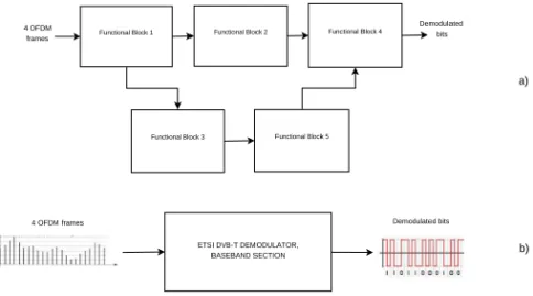
We start our discussion by observing that any radio terminal and, more generally, any system performing signal processing functions, can be represented as the interconnec-tion of a number of constituent funcinterconnec-tional blocks. Simple systems are arranged as a straightforward cascaded “chain” of elementary blocks, more complicated schemes (possibly with feedback connections) look more like a “mesh” of components and connections, as depicted in figure 2.1 a). Focusing for simplicity on a radio receiver, whatever the mesh of blocks and connection is, the end-to-end signal processing function of our system is equivalent to a mathematical function f (...) which maps a certain amount of soft-valued input symbols (for instance the signal samples collected in a given signal frame) into the corresponding hard-valued demodulated information bits as shown in figure 2.1 b). We call the minimum set of soft channel symbols that can be processed independently from the remainder of the stream the Minimum Independent Data Set (MIDS). For the ETSI DVB-T [22] standard (our principal case study) , this would be 4 Orthogonal Frequency-Division Multiplexing (OFDM) frames (i.e. what is called a superframe in [22]). We indicate the size (number of items) of the MIDS with symbol l and with A the cardinality of the alphabet each input datum of the MIDS belongs to.
Functional Block 1 Functional Block 2
Functional Block 3 Functional Block 5 Functional Block 4 ETSI DVB-T DEMODULATOR, BASEBAND SECTION Demodulated bits 4 OFDM frames 4 OFDM frames Demodulated bits a) b)
2.1 Description of the Memory Acceleration design rule 19
The domain of f (...) is then defined as the set of all possible different messages
within a MIDS. We also call input space the domain of f (...) and Ci the cardinality
of such space. Clearly
Ci= Al (2.1)
If we could find a convenient analytical expression for the function f (...), we could consider implementing our sample DVB-T demodulator by programming such analyt-ical expression into a computing system via any high-level programming language like C/C++. This would be a computation-only implementation of the system, one that is completely located at the time end of the time/space trade-off. Such implementation would only (or mainly) take advantage of the computational resources being available on a GPP-based platform, with very little attention to the memory resources that are available.
After this remark on memory resources, it would be natural to think of replacing our function f (...) with a tabular implementation of f (...): a table t(...) containing,
for each of the Alitems of the overall input space, the associated output value. This
would be a memory-only implementation, located at the space end of the trade-off, and would not require any (or would require negligible) real-time computation. On
the other hand, the size Ci of the table would not be practical for any memory
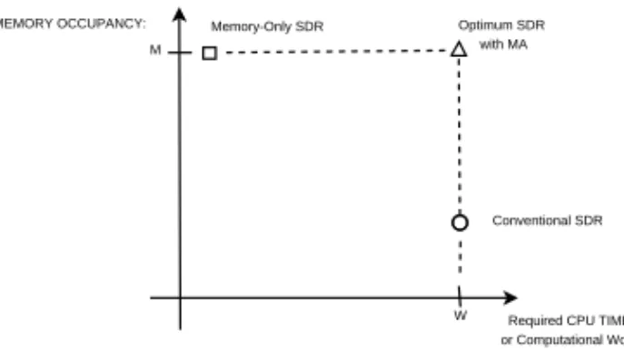
technology available today or in the foreseeable future. The table t(...) could be filled up by running once and forever, at instantiation time (i.e., at the time of initialization or configuration of the terminal) any standard, computation-only, implementation of function f (...) (i.e. the traditional radio system chain) over the entire input space. Such considerations suggest that the path towards optimal SDR implementations lies somewhere in between the two ends, with a hybrid approach that could use both computational and memory resources to the greatest possible extent (situation graphically represented in figure 2.2).
Let us now come back to the mesh representation of the signal processing functions of our SDR. We call this representation the 0-step of a procedure underlying MA, that we label algorithm segmentation. Such 0-step may be the direct translation of the signal processing functions described in a communications standard, in a reference implementation, or, in the parlance of SCA-based SDRs [23], in a waveform. The
implicit assumption in this decomposition is that each of the functional blocks fn(...)
in the mesh is atomic, i.e., impossible to break-up in a further mesh of constituent functional blocks. On the contrary, the aim of our algorithm segmentation approach is
20
The memory option: MA research activity
Required CPU TIME or Computational Work MEMORY OCCUPANCY: Conventional SDR Optimum SDR with MA M W Memory-Only SDR
Figure 2.2: Table boundary after one step, released block is peripheral
just coming to a further decomposition of a functional block fn(...), formerly assumed
to be atomic, into a chain (or mesh) of constituent sub-blocks fn,p(...), p = 1, ..., Pn
whose end-to-end behavior is equivalent to the original function fn(...). One
advan-tage of this is that the input spaces of sub blocks Cin,p will be different from and
significantly smaller than Cin, provided that the segmentation is performed correctly.
Algorithm segmentation cannot be considered as a form of algorithm re-design: as a consequence, algorithm segmentation does not change the overall computational cost of the segmented algorithm. We will describe algorithm segmentation with convenient detail in section 2.1.5.
Figure 2.3: Computational cost weighted functional block representation. Blocks 1 and 4
are peripheral
2.1.2
Acceleration design
An expedient visual representation of the SDR signal processing mesh is obtained
as follows: we call Wn the computational cost of the n-th functional block (required
2.1 Description of the Memory Acceleration design rule 21
Table 2.1: MA / MB-SDR symbols and taxonomy
Symbol Meaning
fn(...) Computation-only implementation of block n
tn(...) Memory-only implementation of block n
l Number of items within the MIDS
A Cardinality of Alphabet for each item of MIDS
Cin Cardinality of input space of block fn(...)
Con Cardinality of output space of block fn(...)
W Total available computational power
Wn Computational cost of block fn(...)
WT B Computational cost of subsystem within table boundary
Wm Computational cost of subsystem replaced by table m
Wr Computational cost of not yet memory-accelerated subsystem
Ωm Computational cost for handling table tm(...)
M Total size of available memory
Mm Total memory footprint of table tm(...)
Sm Data size of items stored in tm(...)
a Acceleration factor
η Acceleration efficiency
ηm Acceleration efficiency of table tm(...)
22
The memory option: MA research activity representation of the SDR in which the size of the functional block is directly propor-tional to such cost, as in figure 2.3. This gives at a glance an indication of the relative computational weight of each block (function) within the whole radio. Let us also
introduce the symbol Ωm as the total computational cost of memory management
for table tm(...), something that has nothing to do with algorithm complexity, but
that represents the cost of memory address calculation plus memory access latency (if significant). The latter parameter can be made equivalent to a computational cost by reducing it to CPU time or to equivalent ops/clock cycles.
We come now to the core of the MA technique. Broadly speaking, the aim of MA is aiding the GPP in processing the informative signal through a proper (extensive) usage of memory resources. Such result is obtained by replacing the functional blocks
fn(...) usually implemented according to a purely-computational (time) approach
(with marginal usage of memory), with pre-computed tables tm(...) as introduced
in 2.1.1. The replacement is done after one or more steps of algorithm segmentation have been carried out, and on the most demanding blocks in terms of computational power only. In subsection 2.1.4, we will introduce the so-called Recursive Table Aggregation Rule (RTAR) that finalizes tables that will have to be implemented into memory, while also calling for algorithm segmentation to be applied upon the convenient functional blocks. In this respect, notice that the input space cardinality
Cin of each fn(...) is usually unrelated to its computational cost Wn. Just to make
an example, consider the data deinterleaver in a DVB-T demodulator, that performs the inverse operation of the interleaver used in the modulator to scatter around the protected bits of an encoded data block in order to protect them from time-correlated errors. The cardinality of the input space of the deinterleaver is the same as that of its own adjacent binary FEC decoder (they bear the same block length), but the computational complexity of the decoder is way larger than that of the deinterleaver.
We already mentioned that, after segmentation, only the most computation-demanding blocks need being implemented in a tabular form. This rule comes from the consid-eration that the amount of memory resources M is finite, and has to be used in an optimal fashion. Performing memory-acceleration (i.e., tabular implementation) of low-complexity blocks would only result in a waste of memory resources, with negligible impact on processing speed. The MA rule attains an optimum configuration whenever the available memory resources are exhausted, and the maximum number of operations (or the maximum possible amount of CPU time) has been replaced by
2.1 Description of the Memory Acceleration design rule 23
memory look-ups implementing the same functions. Replacement of computation-dominated blocks has to follow a hierarchical approach, starting form the most, down to the least demanding, until available memory resources are over.
2.1.3
Table aggregation and cache friendliness
The computational complexity of a tabular implementation tm(...) is not zero, though.
We have to consider in fact the memory management cost Ωm that can be at times
non negligible. From this standpoint, it is apparent that the larger is the number
of functional blocks fn(...) that we collapse into a single tabular implementation
tm(...), the smaller is the total memory management cost Ω of our memory-accelerated
implementation. In addition to this, we must also consider that GPP-based platforms have a hierarchical memory structure with smaller and faster caches in the proximity of the computing cores and bigger, slower extended memories in a more peripheral location of the system. The general rule to use efficiently such hierarchical memory arrangement is storing contiguously in memory information which is used contiguously in time. This means for instance that a series of consecutive blocks in a processing chain are accelerated very efficiently when their processing is aggregated (as far as
possible) into a single table tm(...) whose internal arrangement reproduces the same
cascaded structure of the original chain (RTAR is designed in order to yields this). This happens because if such criterion is observed, either the whole table fits into the CPU cache or any subset of the table is fetched into cache only once and never gets used twice, thus maximizing cache friendliness. Once recognized that aggregating blocks in such a structured way is a virtue per se, we introduce in the next subsection a Recursive Table Aggregation Rule. Following this rule, we can on one hand provide the aggregation of as many functional blocks as possible into the same table, while on the other we can perform algorithm segmentation –which still remains a demanding design task– only for those blocks where it is really needed and useful.
2.1.4
Recursive Table Aggregation Rule
Assuming that we have an atomic mesh decomposition of our end-to-end algorithm (our SDR), what is the optimum level of break-up to replace computation-intensive blocks with tables? We try to give an answer to this fundamental question through the RTAR, whose aim is to come to a balanced (optimum) time/space trade-off in the
24
The memory option: MA research activity design of the SDR, possibly providing also cache friendliness. We start by enclosing
Figure 2.4: Table boundary after one step, released block is peripheral
Figure 2.5: Atomicity limit reached
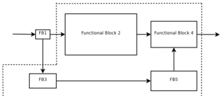
the subsystem we intend to memory-accelerate into a closed line that we call the table boundary (TB). The connections that crosses the TB represent the input/output interface towards the external world of the subsystem under consideration. An atomic block of the subsystem is called peripheral if all of its input or all of its output connections cross the TB. Once this is defined, the RTAR proceeds as follows:
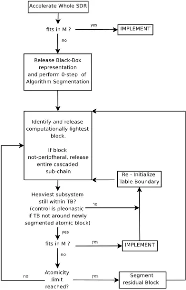
1. (Initialization) Define the whole radio the as the (sub-)system to be
memory-accelerated. This is equivalent to enclosing the entire radio within a TB.
Calculate the size Ci of the table that is necessary to memory-implement the
selected subsystem (the whole radio). If the table fits into memory, then go to step 3
2. (Reduction) Identify the computationally-lightest block contained within the TB and reduce the subsystem by releasing such block (move it outside the TB as in Fig. 2.4). If the released block is not peripheral, then release also all
2.1 Description of the Memory Acceleration design rule 25
Figure 2.6: Example of released block (FB5) being non-peripheral. In this case cascaded
blocks (FB4) are released as well. At next step of the iterative algorithm, formerly released blocks will be enclosed in the new table boundary
equivalent to the enclosed system; if the table fits, then go to step 3), otherwise reduce again until either i) the table fits (in this case, still go to step 3), or ii) the
atomicity limit fn(...) is reached (figure 2.5). If the latter becomes true, perform
algorithm segmentation upon the block fn(...) being currently surrounded by TB
and go back to step 2). 1
3. (Memory-only Implementation) Implement the subsystem being enclosed in the current table boundary by replacing its computation-only functional blocks
with an equivalent table tm(...). If the system still contains blocks not yet
implemented in memory, and memory resources are not exhausted, initialize the table boundary for another MA iteration by enclosing all of the remaining computational blocks of the radio system, then go to step 2).
The proposed RTAR rule is admittedly heuristic - an exhaustive approach to algo-rithm segmentation to find the optimum configuration of the SDR appears unfeasible. Nonetheless, we believe that our rule captures the majority of the achievable MA gain with a manageable approach. In some test cases (conducted upon rather heteroge-neous signal processing algorithms), RTAR was shown to provide substantial speedup
1Note that, in the case atomicity limit is reached, the block which undergoes algorithm seg-mentation is the heaviest block of the whole radio, and therefore the sub-blocks obtained from its segmentation still collectively yield the majority of the computational cost of the SDR. Still, as soon as the first of obtained sub-blocks gets released, we cannot guarantee that this keeps true. Thus, whenever one of the sub-blocks obtained from algorithm segmentation is released, it must be checked whether the table boundary encloses a computational cost WT B which is still greater than the cost of any functional block outside the TB. In case this condition becomes false, the TB must be re-initialized to enclose the entire system and the procedure shall continue from step 2).
26
The memory option: MA research activity factors (roughly one order of magnitude) with an acceptable MA design effort.
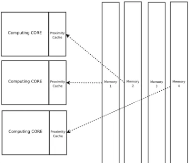
Cache-friendliness provided by RTAR also constitutes the basis for MA compatibility with parallel programming. Memory access contentions that could indeed happen when loading the required memory table (or table portion) from the external Random Access Memory (RAM) into the core-dedicated caches of a multicore computing system can be made extremely sporadic by performing most of the look-ups within the cache, therefore minimizing the number of fetches being necessary from the RAM. For the reader’s convenience, an MA flowchart is sketched in in figure 2.7.
Figure 2.7: Schematic representation of MA Recursive Table Aggregation Rule. Exit
2.1 Description of the Memory Acceleration design rule 27
2.1.5
More on Algorithm Segmentation
As previously stated, Algorithm Segmentation is the process of breaking down a single functional block f (...) into its constituent functional sub-blocks or segments. This process just identifies the segments within a given block f (...) without actually performing any re-design of the segmented algorithm, so that the computational cost of the segmented system f (...) is not changed. A segment is any sub-system of f (...) with a specific and identifiable MIDS over one or more input connections. The output yielded by the processing of such MIDS (the segment output) is in its turn input to another segment (with another, possibly different MIDS) which concurs to build up f (...) as a whole. The gain of the process of segmentation lies just in
the difference between the cardinality Ci of the overall MIDS of f (...), and those
of the constituent segments, Ci,m. The MIDS of the segments are often (much)
smaller than that of f (...). Typically, the overall MIDS has a size that is given by the Least Common Multiple of the segments’ MIDS. Therefore, when considering
(2.1), it turns out immediately that the set of tabular implementations tm(...) of the
segments is dramatically much less demanding than the (global) table t(...) of the whole subsystem, in terms of memory resources.
Considering the extreme variety of architectures and functions of the signal process-ing algorithms in an SDR terminal, tryprocess-ing to find an optimal segmentation/aggregation configuration is very hard. We can just say that the best algorithm segmentation is the one providing the smallest granularity of input spaces of the obtained sub blocks. This is true because the smaller the granularity is, the closer the RTAR will manage to bring the total memory occupancy of the MA-ed SDR to the memory capacity of
the computing platform M . Broadly speaking, the more sub-blocks Nsb algorithm
segmentation obtains from the given block, the better algorithm segmentation was performed.
To sum up, the joint action of algorithm segmentation and RTAR (i.e., the gist of the MA concept) is to i) decompose the given SDR system down to the finest possible level of computational granularity; ii) generate a re-implementation which uses the available memory resources in order to perform as much computation as possible by means of memory look-ups, and iii) do it with the smallest possible computational cost of memory management.
28
The memory option: MA research activity
2.2
Application and performance metrics of MA
2.2.1
MA compatibility with different acceleration techniques
All performance results that will be presented in section 2.3 were obtained by applying MA alone, i.e. by making use of no other performance enhancement technique such as low level (Assembler) programming or code parallelization. Still, such implementation techniques are fully compatible with MA. Compatibility with low level programming is trivial and does not deserve any discussion. For parallel implementation instead, a possible issue lies in the concurrent access to a certain memory area from multiple computing cores. This may call for some form of collision control and consequent performance bottlenecks. Such problem can be substantially mitigated through the “cache friendliness” approach that we mentioned above. Multicore/multiprocessor GPP-based platforms often feature cache memories which are dedicated to each single core as depicted in figure 2.8. Such memories are independently accessed by each of the cores, so that the probability of collision events is zero. Collisions may instead happen when loading the required memory table (or table portion) from the external Random Access Memory (RAM) into the core-dedicated caches as shown in figure 2.8. Appropriate use of a cache-friendly table structure will make these fetches extremely sporadic. Should access contention happen at the RAM-level, it would be rare enough not to degrade system performance. Practical proof of this is provided in [24].
2.2.2
Performance evaluation
To quantify the performance in terms of processing speed-up of the MA technique, we define the acceleration efficiency for any functional block f (...) as
η = PNsb−1 n=0 Wn−P Nt−1 m=0 Ωm PNt−1 m=0 Mm (2.2)
where Nsb is the number of the sub-blocks fn(...) obtained after algorithm
segmenta-tion which are implemented in tabular form, and Ntis the number of tables that will
be used to produce such an implementation as resulting from the application of RTAR. In other words, the acceleration efficiency η is the ratio between the computational effort being saved by means of the resulting memory-based implementations (reduced by the amount of computational work needed for table management) and the total
2.2 Application and performance metrics of MA 29
Figure 2.8: Multiple processing cores, their dedicated caches and table loading from RAM
to the core-dedicated cache
memory footprint being required. A negative value for η indicates that the chosen MA design will reduce system performance. Once the acceleration process is completed, it is possible to calculate the obtained acceleration factor a as
a =Wr+ PNsb−1 n=0 Wn Wr+P Nt−1 m=0 Ωm =1 + PNsb−1 n=0 Wn/Wr 1 +PNt−1 m=0 Ωm/Wr (2.3)
where Wr accounts for the total computational cost of the remaining blocks which
where not implemented in memory.
As previously stated, different algorithms offer different opportunities for segmen-tation. The consequence of this statement is that it is very difficult to give an upper bound for a. Still, a naive and probably loose upper bound for a can be found assuming that the whole radio can be memory-accelerated. In such condition we get
amax= PNsb−1 n=0 Wn PNt−1 m=0 Ωm ≤ PNsb−1 n=0 Wn PNt−1 m=0 [Lm+ (im−1)(x + σ)] (2.4)
where Nsb is now the total number of computational blocks within the segmented
system, Lmis the access latency for each table (that depends on the table size and on
the chosen implementation platform), imis the number of inputs to each table, x is the
30
The memory option: MA research activity
cost of one sum with a variable. All such quantities, including Lm, can be expressed
in terms of number of equivalent elementary operations, or of required CPU time.
The term (im−1)(x + σ) is a lower bound for Ωm that only considers the simplest
elementary computation of the memory address.
2.3
A case study: the DVB-T Viterbi decoder
2.3.1
MA design for the Viterbi decoder
We wish to describe in this section the results we obtained by applying the MA technique to a fully software, GPP-based implementation of a an ETSI DVB-T [22] receiver called SR-DVB [25], [26], which will be instead described as a whole in section 3.4. Our starting point was an optimized C/C++ source code with no parallelism, developed in-house with a conventional computation-dominated approach. In such reference implementation, the demodulator turned out to run on a set of pre-recorded input signal samples roughly 10 times slower than the real time. R-DVB included all of the ETSI DVB-T demodulation functions (except synchronization and equalization), starting form a stream of previously synchronized and equalized baseband I-Q samples acquired from a standard broadcasting band, and delivering the demodulated MPEG Transport Stream (TS). Our GPP test and reference platform is just a run-of-the-mill Intel quad core Q9400 CPU clocked at 2.66 GHz, our software does not make any use of parallelization: all code is single threaded and only one of the four cores available on the platform is actually used.
We set forth to apply MA and see if an acceleration factor of at least 10 could be gained, thus allowing for real-time processing of a DVB channel. An all-memory implementation of the entire ETSI DVB-T demodulator as a single memory table (i.e. by applying no RTAR cycle) was of course not feasible. Therefore, we profiled the computational cost of the conventional demodulation chain on a block-by-block basis (akin to what appears in Fig. 2.3), thus performing what we called the 0-step of algorithm segmentation. It was immediately clear that the K=7 Viterbi Decoder (VD) [27] included in the demodulation chain [22] was by far the heaviest block of the system (followed at a large distance by time/frequency signal synchronization and FFT-based OFDM demodulation) accounting for about 80% of the CPU effort. According to RTAR, the VD was therefore meant to be the first block to undergo memory
2.3 A case study: the DVB-T Viterbi decoder 31
acceleration. Such activity produced a Memory Accelerated, novel implementation of the VD itself (the MA-VD, to be further detailed in the following) that relies almost entirely upon memory resources. The MA-VD, together with the subsequent MA implementation of the signal synchronization functions described in section 2.4, was the enabling factor to to obtain a real-time, fully software ETSI DVB-T receiver on a low budget off-the-shelf GPP [24].
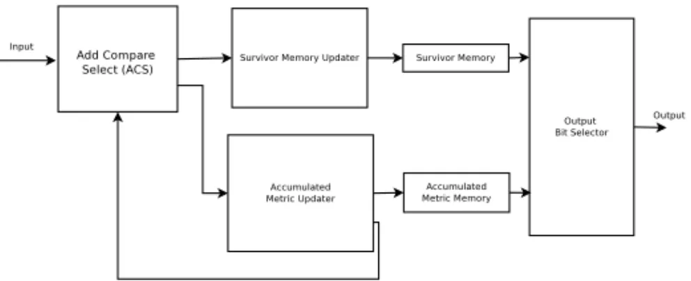
After identifying the VD as the most computation-intensive block, we started ap-plying our technique of segmentation and aggregation as in 2.1.4. A classical decom-position of the VD is shown in figure 2.9 where all of the functions are meant to be implemented through pure computation. The blocks of such decomposition implement four different functions [28]: i) Add-Compare-Select (ACS), ii) refresh of the survivors (the memories of the tentative decoded bits for each state of the decoder), iii) update of the accumulated metrics (weights) for each of the survivors, and iv) selection of the likeliest (smallest metric), associated with corresponding output of the decoded bit after a certain decoding latency (depth). After such a coarse-grain segmentation,
the input space cardinalities Cin were still far too large to fit into the available
memory. We iterated RTAR until segmentation produced the much finer-grained implementation of figure 2.10, with convenient table boundaries. The constituent sub-blocks then were:
• Branch Metrics Computer (BMC)
• Sum of branch metrics to the accumulated metrics (ADD)
• Accumulated metrics comparison and selection (C & S)
• Storage and update of accumulated metrics (AMM)
• Storage and update of survivors (SM)
The sub-blocks come in number of 64 since the decoder has 64 internal states corre-sponding to the number of states of the DVB-T convolutional channel encoder. We
finally were awarded with candidate tables having reasonable and practical Ci. RTAR
was then ready to start re-aggregation of the segmented system into larger tables intended for direct memory implementation. The configuration we attained at, after a number of further RTAR cycles is shown in figure 2.11, where the distinction between memory-only (space, t(...)) and computation-only (time, f (...)) implementation is
32
The memory option: MA research activity clearly shown. In such implementation, the ACS function for as many as 4 states is lumped into a single memory look up. Another memory table implements the selection of the likeliest state, while update of decoded bit memories and of current metrics for all states is still being performed through pure computation by the f (...)1 and f (...)2 blocks respectively. This arrangement is the result of a judicious allocation of memory and computational resources, and the degree of its optimality depends on the particular computing platform that we assumed. More time blocks could have been implemented as space blocks with a somewhat more ”extreme” exploitation of available memory (that we did not want to pursue).
The final result of MA design is that the computational cost required to perform the single memory look-up is by far smaller than the sum of all elementary operations that would be needed in order to derive in a computation-dominated (i.e. time-dominated) fashion the required result. For this reason we may also claim that the described approach is also power-saving, and reduces the power efficiency gap between SW and HW implementations of the radio terminal, without losing anything in reconfigurability and flexibility of the system. This comes of course at the cost of larger memory occupancy.
Figure 2.9: Classical functional block decomposition of the Viterbi Decoder. All displayed
functional blocks are implemented through pure computation
On the reference platform described in section 2.3, the processing (decoding) of a fixed amount of data (namely 631, 701, 504 bits), by the standard C/C++ computation-dominated implementation of the DVB-T VD took about 66.56 seconds, thus yielding a computational requirement of 101.31 nanoseconds per decoded bit. The MA imple-mentation above takes on the contrary 6.35 seconds (10.05 nanoseconds per decoded
2.4 Other memory-accelerated algorithms 33
of the memory-accelerated implementation is 50.0 MiB which, by today’s standards, is negligible on a GPP-based platform. Residual, non memory-accelerated computation is responsible for a computation time of 0.5 seconds, while decoding the same amount of data mentioned above, resulting in a computational load of 0.79 nanoseconds per
decoded bit. Such figure is indeed a good estimate of what we called Wr in 2.4.
The sum of table-management computational costs Ωmassociated with all the tables
implementing the VD is therefore 5.85 seconds, equivalent to 9.26 nanoseconds per
decoded bit. The acceleration efficiency η for our implementation2
turns out to be ηM A−V D= 101.31 − 0.79 − 9.26 50 = 1.82 [ nanosec/decoded bit M iB ] (2.5)
The benchmark CPU exhibiting such acceleration result has a 6M cache size. Tests with smaller CPUs featuring smaller caches (3M, 2M, 1M, 512K) exhibited quasi-linear scaling of the total CPU time required by the MA implementation with the cache size, suggesting an extremely strong dominance of cache size over clock fre-quency. Considering the nature of the MA technique, such dominance was expected (indeed it was aimed-for), still, the quasi-linear behaviour was pretty surprising.
It is not possible instead to provide an estimate for amax as such maximization is
directly dependent on the optimality of algorithm segmentation for the considered algorithm. Optimality of algorithm segmentation for a given DSP algorithm is in fact still an open research issue at the time of writing.
2.4
Other memory-accelerated algorithms
In the last part of this chapter, some results obtained while applying MA to other algorithms are worth to be mentioned as well. Within the synchronization section of the SR-DVB receiver, a carrier frequency fractional (i.e. expressed as a fraction of OFDM subcarrier spacing) offset corrector, which used to be implemented by means of pure calculus, was accelerated by a factor 46.3 after undergoing MA. In short, within this very basic MA application, a single, computationally-implemented, oscillator generating any complex tone that could be required to compensate the estimated frac-tional offset is algorithm-segmented down to a set of oscillators capable of generating
2The presented performance results were obtained by running the algorithm under Linux Fedora 10 and compiling the source code with the g++ compiler, version 4.3.2 − 7
34
The memory option: MA research activity only a single frequency. Generated complex tones are spectrally spaced by two times the standard deviation of the fractional frequency offset estimator, thus, the oscillator set is kept finite and small. Each of such sub-blocks (sub-oscillators) is implemented by means of a memory table, therefore obtaining full memory implementation of the fractional frequency offset corrector block as shown in figure 2.12.
We believe that this example, although very simple and providing very little or no innovation wrt current common practice, suggests a different and much more general way to think of Look-Up Tables (LUTs) in SDR implementation. Such generality, as described in section 2.1, can be extremely useful when it comes to use memory in order to speed up much more complicated algorithms.
As discussed above, functional blocks inherently working on large amounts of data (i.e. featuring big MIDS) require well-designed segmentation in order to be conve-niently accelerated. When such blocks do perform very basic operations on such broad data sets, they are difficult to segment. Still, it was possible to obtain quite a significant memory-acceleration of a computationally heavy algorithm presenting such challenges, namely the OFDM time and frequency offset estimator described by van de Beek, Sandell and Borjesson in [29]. Memory-accelerated implementations obtained so far provided acceleration factors as big as 11.996 which are expected to grow by means of further development and will be described in future MA-related works. Reference HW/SW platform for this implementation is the same as described above.
We believe that acceleration factors of about one order of magnitude in terms of computational efficiency obtained by applying MA to the two highly diverse signal processing algorithms described above (namely an hard-valued Viterbi decoder and a soft-valued, correlator-based OFDM synchronizer), already suggest the generality of MA approach as well as its applicability to an extremely wide variety of radio signal processing algorithms.
For such a reason, we propose MA as an implementation technique for radio signal processing within SDR systems which can provide substantial boost to their perfor-mances and therefore move SDR technologies much closer to market segments they are currently excluded from, because of their poor energy efficiency.
An issue to be discussed for memory-dominated SDRs is the initialization process. Whenever the terminal has to be (re-)configured, the memory tables in the space-implemented blocks have to be (re-)initialized. This can be done by i) bootstrapping