Titolo
Development and validation of an approach and
numerical models for safety analysis
o
f
FBR
Descrittori
Tipologia del documento: Collocazione contrattuale:
Rapporto Tecnico
Accordo di programma ENEA-MSE su sicurezza nucleare e Reattori di IV generazione
Reattori Nucleari Veloci, Termoidraulica dei reattori nucleari Sicurezza nucleare, Analisi incidentale
Argomenti trattati:
Sommario
Il report rappresenta un contributo all'analisi numerica di scenari operativi e incidentali e consiste nella messa a punto, nell'applicazione e nella validazione di unapproccio edi modelli per analisi di sicurezza di reattori veloci di IV generazione. L'attività è svolta insinergia con International Coordinated Research Project (CRP) on EBR-TI Shutdown Heat Removal Tests promosso dall'IAEA. L'attività, di lungo respiro, èmulti-physics emulti-scale e trarrà beneficio dalla disponibilità di dati .sperimentali misurati in reattore durante l'esecuzione di test sperimentali: protected (SHRT-17) ed unprotected (SHRT-45r) loss of flow nel reattore americano di ricerca EBR-II. L'attività nel suo complesso richiede uno sforzo sinergico di differenti competenze tecniche, dalla fisica del reattore, alla termoidraulica di sistema, alla fluidodinamica computazionale, alla termomeccanica del fue!.
Il documento presenta l'impianto EBR-II, oggetto delle simulazioni numeriche, e descrive il test sperimentale SHRT-17. Successivamente, riporta il modello termoidraulico realizzato per il codice di sistema RELAP5-3D©,
la qualifica della nodalizzazione, il raggiungi mento dello stato stazionario e la simulazione blina dell'esperimento. I risultati ottenuti sono stati poi confrontati con i dati sperimentali rilasciati nell'ambito del benchrnark: il documento presenta un'analisi dettagliata finalizzata alla preparazione dell'analisi diposttest. Visto il livello di dettaglio della strumentazione negli assemblies sperimentali XX09 e XXl O, installati nel driver del reattore, è stato realizzato un modello CFD attraverso ilcodice ANSYS CFX per fornire informazioni dettagliate
sulla distribuzione di temperature nell'assembly, partendo dalle condizioni al contorno fornite dalla termoidraulica e dalla neutronica. Il modello include in principio la conduzione nelle guaine e nel filo, la convezione nel refrigerante, la conduzione nella scatola esagonale ed il bypass flow. Infine, si descrivono le
attività di neutronica previste nell'ambito dell'attività, finalizzate prevalentemente alla valutazione dei coefficienti di reattività dei due test sperimentali (codici ERANOS e MONTECARLO) e alla simulazione del transitorio SHRT-45r conla cinetica neutronica tridimensionale (codice PHYSICS).
Note: Autori:
A.Del Nevo, I.Di Piazza, C.Parisi, P. Console Camprini (ENEA) E. Martelli, P.Balestra, F.Giannetti, A. Naviglio (CIRTEN-UNIROMAl)
1 NOME
FIRMA
Il l fl
A.Del Nevo M. T, ~(ino M.T Il
Ir/
t
;
no
O EMISSIONE 25/09/14 NOME r o
/
I
~
1
:
:/U0
/
~lju../vV1
FIRMAS
UMMARYThe present report is a contribution to the “Numerical analysis of operational scenarios and incidental” activity, that consists in the development, application and validation of approach and models for safety analysis of liquid metal Gen. IV reactors. The activity, developed in the framework of the International Coordinated Research Project (CRP) on EBR-II Shutdown Heat Removal tests promoted by IAEA, is multi-physics and multi-scale and will require the synergistic effort of different technical skills. The report, that summarize the main parts of the activity, is divided into two parts.
The former presents first the EBR-II plant and SHRT-17 description, correlated with the experimental data available. Then, the 3D thermalhydraulic model realized with RELAP5-3D© system code is presented. On the basis of the available data and initial conditions the steady state conditions are verified and the blind simulation of SHRT-17 is performed. The comparison between results obtained and the experimental data is executed and presented in the report.
The second part describes the CFD model, realized with ANSYS CFX code to provide detailed information about temperature distribution in the assembly, on the basis of information provided for XX09 and XX10 assemblies instrumentation. The model developed includes the entire pin bundle length with the preceding and follower unheated regions and the heated one. The cladding and wire conduction, the coolant convection, the hexagonal box and the bypass flow conduction are also included in the model.
The last two sections present the neutronic model that will be implemented with the deterministic code ERANOS and with MCP code, respectively.
L
IST OF CONTENTSS
UMMARY... 3
L
IST OF FIGURES... 6
L
IST OF TABLES... 10
L
IST OF ABBREVIATIONS... 12
INTRODUCTORY
REMARKS ... 14
1
Framework... 14 1.1 Objective of the activity ... 151.2
D
ESCRIPTION OFEBR-II
PLANT... 16
2
Introduction ... 162.1 EBR-II plant overview ... 16
2.2 Reactor Core ... 17
2.3 Coolant System... 20
2.4
DESCRIPTION
OF
THE
SHRT-17
EXPERIMENT ... 30
3
Objectives of SHRT-17 ... 303.1 Configuration of the facility, boundary and initial conditions of SHRT-17 ... 30
3.2 Description of SHRT-17 ... 33 3.3
RELAP5-3D
© NODALIZATION... 62
4
RELAP5-3D©v4.0.3 code... 62 4.1 EBR-II nodalization ... 63 4.2 Nodalization features ... 66 4.3 Nodalization and code models verifications ... 834.4 Pressure Drops Analyses ... 83
4.4.1 Heat exchange test ... 86
4.4.2
B
LIND SIMULATION OFSHRT-17... 91
5
Steady state results ... 915.1 SHRT-17 transient results ... 91
5.2
CFD
CODE PRELIMINARY ASSESSMENT FORLM
COOLED WIRE-
SPACEDF
UEL6
A
SSEMBLY... 113
The experimental facility... 113
6.1 The test section and the rod bundle instrumentation ... 114 6.2
The CFD model ... 116 6.3
Results for Bundle 2A ... 117 6.4
CFD
MODEL OF THEXX09
I
NSTRUMENTEDFA... 118
7
Numerical Methods ... 118 7.1
The CFD model of the EBR2 XX09-XX10 ... 119 7.2
Results and future work ... 121 7.3
ERANOS
CORE MODEL... 130
8
EBR-II
MCNP
N
EUTRONICM
ODELLING... 132
9
C
ONCLUSIVE REMARKS AND FOLLOW UP... 134
10
L
IST OF FIGURESFig. 1 – EBR-II Primary Tank Sodium Flow Paths. ... 24
Fig. 2 – EBR-II Plant Schematic. ... 24
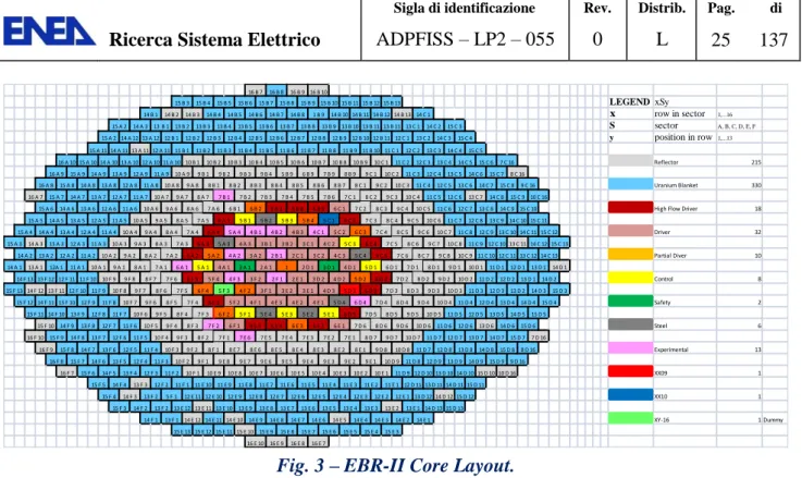
Fig. 3 – EBR-II Core Layout. ... 25
Fig. 4 – EBR-II, SHRT-17 Core Loading Pattern (First 8 Rows). ... 25
Fig. 5 – EBR-II, MARK-II AI Subassembly Configuration. ... 26
Fig. 6 – EBR-II Primary Tank Layout. ... 27
Fig. 7 – EBR-II Primary Tank Vessel. ... 27
Fig. 8 – EBR-II Reactor Vessel. ... 28
Fig. 9 – EBR-II High - and Low - Pressure Inlet Plena. ... 28
Fig. 10 – EBR-II Intermediate Heat Exchanger. ... 29
Fig. 11 – EBR-II, SHRT-17: Power per Subassembly. ... 42
Fig. 12 – EBR-II, SHRT-17: Flow per Subassembly in gallons per minute. ... 43
Fig. 13 – EBR-II, SHRT-17: Primary Pump Speeds. ... 44
Fig. 14 – EBR-II, SHRT-17: Normalized Fission Power. ... 44
Fig. 15 – EBR-II, SHRT-17: Total, Fission and Decay Heat Power. ... 45
Fig. 16 – EBR-II, SHRT-17: IHX Intermediate Side Inlet Sodium Mass Flow Rate. ... 45
Fig. 17 – EBR-II, SHRT-17: IHX Intermediate Inlet Sodium Temperature. ... 46
Fig. 18 – EBR-II, SHRT-17: Pump#2 Mass Flow Rate. ... 47
Fig. 19 – EBR-II, SHRT-17: High-and Low-Pressure Mass Flow Rate. ... 47
Fig. 20 – EBR-II, SHRT-17: Core Inlet Temperature. ... 48
Fig. 21 – EBR-II, SHRT-17: Lower Plenum Temperature. ... 48
Fig. 22 – EBR-II, SHRT-17: Upper Plenum Temperature. ... 49
Fig. 23 – EBR-II, SHRT-17: Average Subassembly Outlet Temperatures. ... 49
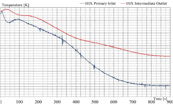
Fig. 24 – EBR-II, SHRT-17: IHX Primary Inlet and Intermediate Outlet Temperature. ... 50
Fig. 25 – EBR-II, SHRT-17: IHX Primary Side Temperture. ... 50
Fig. 26 – EBR-II, SHRT-17: XX09 Mass Flow Rate. ... 51
Fig. 27 – EBR-II, SHRT-17: XX10 Mass Flow Rate. ... 51
Fig. 28 – EBR-II, SHRT-17: XX09 Flowmeter Temperature. ... 52
Fig. 29 – EBR-II, SHRT-17: XX09 Mid Core Temperature ... 52
Fig. 30 – EBR-II, SHRT-17: XX09 Top of Core Temperature ... 53
Fig. 31 – EBR-II, SHRT-17: XX09 Above Core Temperature. ... 53
Fig. 33 – EBR-II, SHRT-17: XX09 Thimble Annulus Temperature. ... 54
Fig. 34 – EBR-II, SHRT-17: XX10 Flowmeter Temperature. ... 55
Fig. 35 – EBR-II, SHRT-17: XX10 Mid Core Temperature. ... 55
Fig. 36 – EBR-II, SHRT-17: XX10 Top of Core Temperature. ... 56
Fig. 37 – EBR-II, SHRT-17: XX10 Above Core Temperature. ... 56
Fig. 38 – EBR-II, SHRT-17:XX10 Coolant Exit Temperature. ... 57
Fig. 39 – EBR-II, SHRT-17: XX10 Coolant Outlet Temperature. ... 57
Fig. 40 – EBR-II, SHRT-17:XX10 Thimble Annulus Temperature. ... 58
Fig. 41 – EBR-II, SHRT-17: Subassembly Outlet Temperature (Row 1 and 2). ... 58
Fig. 42 – EBR-II, SHRT-17: Subassembly Outlet Temperature (Row 3). ... 59
Fig. 43 – EBR-II, SHRT-17: Subassembly Outlet Temperature (Row 4). ... 59
Fig. 44 – EBR-II, SHRT-17: Subassembly Outlet Temperature (Row 5 and 6). ... 60
Fig. 45 – EBR-II, SHRT-17: Subassembly Outlet Temperature (Row 7). ... 60
Fig. 46 – EBR-II, SHRT-17: Subassembly Outlet Temperature (Reflector and Blanket). ... 61
Fig. 47 – EBR-II SHRT-17, RELAP5-3D©: schematization of 3D components. ... 67
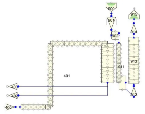
Fig. 48 – EBR-II SHRT-17, RELAP5-3D©: plant scheme. ... 67
Fig. 49 – EBR-II SHRT-17, RELAP5-3D©: scheme of pumps, high and low pressure flow lines. .... 68
Fig. 50 – EBR-II SHRT-17, RELAP5-3D©: scheme of Z-PIPE, IHX primary and secondary side. ... 68
Fig. 51 – EBR-II SHRT-17, RELAP5-3D©: MARK-II AI fuel assembly ... 69
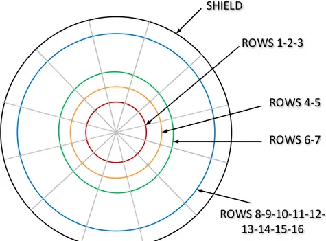
Fig. 52 – EBR-II SHRT-17, RELAP5-3D©: plane view of reactor core subdivision. ... 69
Fig. 53 – EBR-II SHRT-17, RELAP5-3D©: Pressure Drops Test. ... 88
Fig. 54 – EBR-II SHRT-17, RELAP5-3D©: Pressure Drops Test. ... 89
Fig. 55 – EBR-II SHRT-17, RELAP5-3D©: Heat Exchange Test. ... 90
Fig. 56 – EBR-II SHRT-17, RELAP5-3D©: Pressure Drops Versus Length. ... 96
Fig. 57 – EBR-II SHRT-17, RELAP5-3D©: Primary Pump Sodium Mass Flow Rate. ... 97
Fig. 58 – EBR-II SHRT-17, RELAP5-3D©: Primary Pump Sodium Mass Flow Rate (Detail). ... 97
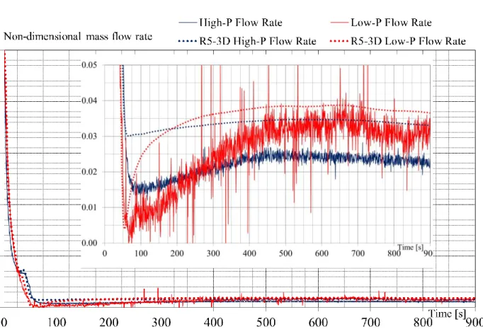
Fig. 59 – EBR-II SHRT-17, RELAP5-3D©: High and Low-Pressure Flow Rate (Non-dim.). ... 98
Fig. 60 – EBR-II SHRT-17, RELAP5-3D©: High and Low-Pressure Inlet Plenum Temperature. .... 98
Fig. 61 – EBR-II SHRT-17, RELAP5-3D©: Lower Plenum Temperature. ... 99
Fig. 62 – EBR-II SHRT-17, RELAP5-3D©: Upper Plenum Temperature. ... 99
Fig. 63 – EBR-II SHRT-17, RELAP5-3D©: IHX Primary Inlet and Intermediate Outlet Temperature. ... 100
Fig. 64 – EBR-II SHRT-17, RELAP5-3D©: IHX Primary Side Outlet Temperature. ... 100
Fig. 66 – EBR-II SHRT-17, RELAP5-3D©: XX10 Mass Flow Rate. ... 101
Fig. 67 – EBR-II SHRT-17, RELAP5-3D©: XX09 Flowmeter Temperatures. ... 102
Fig. 68 – EBR-II SHRT-17, RELAP5-3D©: XX09 Mid Core Temperature. ... 102
Fig. 69 – EBR-II SHRT-17, RELAP5-3D©: XX09 Top of Core Temperature. ... 103
Fig. 70 – EBR-II SHRT-17, RELAP5-3D©: XX09 Above Core Temperature. ... 103
Fig. 71 – EBR-II SHRT-17, RELAP5-3D©: XX09 Coolant Outlet Temperature. ... 104
Fig. 72 – EBR-II SHRT-17, RELAP5-3D©: XX09 Thimble Annulus Temperature... 104
Fig. 73 – EBR-II SHRT-17, RELAP5-3D©: XX10 Flowmeter Temperature. ... 105
Fig. 74 – EBR-II SHRT-17, RELAP5-3D©: XX10 Mid Core Temperature. ... 105
Fig. 75 – EBR-II SHRT-17, RELAP5-3D©: XX10 Top of Core Temperature. ... 106
Fig. 76 – EBR-II SHRT-17, RELAP5-3D©: XX10 Above Core Temperature. ... 106
Fig. 77 – EBR-II SHRT-17, RELAP5-3D©: XX10 Coolant Exit Temperature. ... 107
Fig. 78 – EBR-II SHRT-17, RELAP5-3D©: XX10 Coolant Outlet Temperature. ... 107
Fig. 79 – EBR-II SHRT-17, RELAP5-3D©: XX10 Thimble Annulus Temperature... 108
Fig. 80 – EBR-II SHRT-17, RELAP5-3D©: Subassembly Outlet Temperature (Row 1 and 2). ... 108
Fig. 81 – EBR-II SHRT-17, RELAP5-3D©: Subassembly Outlet Temperature ( Row 3). ... 109
Fig. 82 – EBR-II SHRT-17, RELAP5-3D©: Subassembly Outlet Temperature (Row 4). ... 109
Fig. 83 – EBR-II SHRT-17, RELAP5-3D©: Subassembly Outlet Temperature (Row 5 and 6). ... 110
Fig. 84 – EBR-II SHRT-17, RELAP5-3D©: Subassembly Outlet Temperature (Row 7). ... 110
Fig. 85 – EBR-II SHRT-17, RELAP5-3D©: Subassembly Outlet Temperature (Row 9, 12 e 16). .. 111
Fig. 86 – EBR-II SHRT-17, RELAP5-3D©: Core Outlet Temperature. ... 111
Fig. 87 – EBR-II SHRT-17, RELAP5-3D©: Peak Coolant Temperature. ... 112
Fig. 88 – Fuel Failure Mockup test facility at ORNL. ... 113
Fig. 89 – Bundle 2A test section of the FFM facility at ORNL. ... 114
Fig. 90 – Locations of ungrounded-junctions in wire-wraps of bundle 2A. ... 115
Fig. 91 – Locations of grounded-junctions in wire-wraps and heater internal thermocouples of bundle-2A. ... 115
Fig. 92 – Layout of the CFD model developed for the bundle-2A. ... 116
Fig. 93 – Comparison of pin temperature predictions at different heights with TEST SERIES 4-RUN105 experimental results. ... 118
Fig. 94 – Comparison of duct (wrap internal) temperature predictions at different heights with TEST SERIES 4-RUN105 experimental results. ... 118
Fig. 95 – Overview of the CFD model for the XX09/XX10 FA of the EBR II reactor. ... 120
Fig. 96 – Cross section view of the CFD model for the XX09/XX10 FA of the EBR II reactor. ... 120
Fig. 98 XX09 Instrumented subassembly axial section... 124
Fig. 99 XX09 Instrumented subassembly instrument loading. ... 124
Fig. 100 – Perspective view of the temperature field in the rod bundle XX09 by CFD simulation, CS03. ... 125
Fig. 101 – Temperature in K against the thermocouple number for section MTC, CS03: comparison between experimental data and numerical results... 126
Fig. 102 – Temperature in K against the thermocouple number for section TTC, CS03: comparison between experimental data and numerical results... 126
Fig. 103 – Temperature in K against the thermocouple number for section 14TC, CS03: comparison between experimental data and numerical results... 126
Fig. 104 – Temperature contours in the XX09 FA , CS03, in the measuring planes, according to the CFD simulation. ... 128
Fig. 105 – Secondary velocity vector plot in the MTC cross-section. The color scale is the module of the vector. ... 128
Fig. 106 – EBR-II: Axial breakdown of driver fuel subassembly Mark-II AI. ... 130
Fig. 107 – MCNP SFR Core Neutronic Modelling. ... 132
L
IST OF TABLESTab. 1 – EBR-II subassembly fuel elements design parameters (nominal). ... 23
Tab. 2 – EBR-II subassembly structure design parameters (nominal). ... 23
Tab. 3 – EBR-II, SHRT-17 Test Description. ... 37
Tab. 4 – EBR-II, SHRT-17 Initial Conditions. ... 37
Tab. 5 – EBR-II primary pump parameters. ... 37
Tab. 6 – EBR-II, SHRT-17: Primary Pump Speeds. ... 38
Tab. 7 – EBR-II, SHRT-17: Total, Fission and Decay Heat Power. ... 38
Tab. 8 – EBR-II, SHRT-17: Intermediate IHX Inlet Sodium Flow rate. ... 39
Tab. 9 – EBR-II, SHRT-17: Intermediate IHX Inlet Sodium Temperature. ... 39
Tab. 10 – EBR-II, SHRT-17: Facility configuration. ... 39
Tab. 11 – EBR-II, SHRT-17: imposed sequence of main events. ... 40
Tab. 12 – EBR-II, SHRT-17: resulting sequence of main events. ... 41
Tab. 13 – EBR-II nodalization:adopted code resources ... 70
Tab. 14 – EBR-II SHRT-17, RELAP5-3D©: pool region ... 70
Tab. 15 – EBR-II SHRT-17, RELAP5-3D©: coolant system. ... 73
Tab. 16 – EBR-II SHRT-17, RELAP5-3D©: reactor core ... 74
Tab. 17 – EBR-II SHRT-17, RELAP5-3D©: pump parameter. ... 74
Tab. 18 – EBR-II SHRT-17, RELAP5-3D©: pump model, single phase homologous curves ... 75
Tab. 19 – EBR-II SHRT-17, RELAP5-3D©: Driver assembly ... 76
Tab. 20 – EBR-II SHRT-17, RELAP5-3D©: Safety Rod assembly ... 76
Tab. 21 – EBR-II SHRT-17, RELAP5-3D©: Control Rod assembly ... 76
Tab. 22 – EBR-II SHRT-17, RELAP5-3D©: Core Steel assembly ... 77
Tab. 23 – EBR-II SHRT-17, RELAP5-3D©: XX10 assembly ... 77
Tab. 24 – EBR-II SHRT-17, RELAP5-3D©: XX09 assembly ... 77
Tab. 25 – EBR-II SHRT-17, RELAP5-3D©: High Flow Driver assembly ... 78
Tab. 26 – EBR-II SHRT-17, RELAP5-3D©: Inner Reflector assembly ... 78
Tab. 27 – EBR-II SHRT-17, RELAP5-3D©: Outer Reflector assembly ... 78
Tab. 28 – EBR-II SHRT-17, RELAP5-3D©: Blanket assembly ... 79
Tab. 29 – EBR-II SHRT-17, RELAP5-3D©: correspondence between core assemblies and code nodalization ... 82
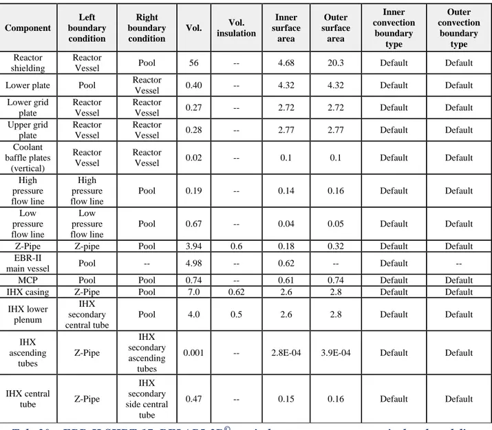
Tab. 30 – EBR-II SHRT-17, RELAP5-3D©: main heat structures geometrical and modeling features. ... 82
Tab. 32 – EBR-II SHRT-17, RELAP5-3D©: Heat Exchange Test, initial conditions. ... 87
Tab. 33 – EBR-II SHRT-17, RELAP5-3D©: steady-state comparison. ... 95
Tab. 34 – EBR-II SHRT-17, RELAP5-3D©: mass flow rate distribution. ... 96
Tab. 35 – Geometrical parameters of the Bundle 2A test section... 115
Tab. 36 – Sodium properties implemented in the CFD model. ... 116
Tab. 37 – Parameters used for a CFD simulation: stationary case CS03 at full power from RELAP input. ... 121
Tab. 38 – Distance h of the measurement sections (MTC, TTC, 14TC) in the streamwise direction from the beginning of the active region. ... 122
Tab. 39 – Comparison between experimental and numerical CFD results for CS03 (XX09). ... 123
Tab. 40 – EBR-II SHRT-17: Test matrix for the CFD IS method to be performed in 2014-2015. .. 129
Tab. 41 – EBR-II: Geometry and composition for central core subassembly Mark-II AI in ECCO cell code. ... 131
L
IST OF ABBREVIATIONS3D Three Dimensional
ANL Argonne National Laboratory
ATC Annulus Thimble Thermocouple
BAF Bottom of Active Fuel
BOP Balance of Plant
CEA Commissariat à l’énergie atomique et aux énergies alternatives
CFD Computational Fluid Dynamics
CIAE China Institute of Atomic Energy
CRP Coordinated Research Project
DAS Data Acquisition System
EBR-II Experimental Breeder Reactor II
EC European Commission
EU European Union
FA Fuel Assembly
FR Fast Reactor
GEN IV Generation IV
GFR Gas-Cooled Fast Reactor
GIF Generation IV International Forum
gpm United Sates gallon per minute
HFD High-Flow Driver
HWCR High Worth Control Rod
IAEA International Atomic Energy Agency
IB Inner Blanket
IFR Integral Fast Reactor
IHX Intermediate Heat Exchanger
INCOT In-Core Instrument Test facility
INL Idaho National Laboratory
INSAT Instrumented Subassembly
IPPE Institute of Physics and Power Engineering
JAEA Japan Atomic Energy Agency
KAERI Korea Atomic Energy Research Institute
KINS Korean Institute for Nuclear Safety
LFR Lead-Cooled Fast Reactor
LWR Light Water Reactor
LMR Liquid Metal Reactor
MCP Main Coolant Pump
M-G Motor-Generator set
NK Neutron Kinetics
OB Outer Blanket
ORNL Oak Ridge national Laboratory
OTC Outlet-Coolant Thermocouple
PPS Plant Protection System
PS Primary Side
R&D Research and Development
SCWR Supercritical Water Reactor
SDC Safety Design Criteria
SFR Sodium Fast Reactor
SHRT Shutdown Heat Removal Test
SS Secondary Side
SSC Structures, Systems and Components
TAF Top of Active Fuel
TH Thermal-Hydraulic
SYS System
TTC Top-of-core Thermocouple
ULOF Unprotected Loss-of-Flow
INTRODUCTORY
REMARKS
1
Framework 1.1
The activity is developed and set-up in synergy of IAEA Coordinated Research Project (CRP) on
EBR-II Shutdown Heat Removal Tests (SHRT) [1].
The CRP aims at improving design and simulation capabilities in fast reactor neutronics, thermal hydraulics, plant dynamics and safety analyses through benchmark analyses of a protected and an unprotected loss-of flow test from the EBR-II SHRT program. Activities include core physics and thermal-hydraulics/safety assessments. Investigations of thermal hydraulics characteristics and plant behavior focus on predicting natural convection cooling accurately by evaluating the reactor core flow and temperatures in comparison to experimental data.
The activity has been established to support validation of simulation tools and models for the safety analysis of liquid metal fast reactors. Validated tools and models are needed both to evaluate liquid metal fast reactors passive safety phenomena and to assess reactor designs incorporating passive features into the system response to accident initiators.
Passive safety response in liquid metal fast reactors is the result of reactor design features that shut down the reactor, remove residual heat, and keep the core cooled during accidents. In addition to the Doppler effect, negative reactivity feedback mechanisms can be used to passively shut down the fission process. Negative reactivity feedback mechanisms are based on thermal expansion and contraction of structural materials, which affects neutron leakage in the fast spectrum core. Radial and axial core expansion, subassembly bowing, and control rod driveline expansion are examples of these passive reactivity feedbacks. Coolant density changes in sodium are utilized in the design to produce natural circulation flow, thus to keep the core cooled when forced circulation is lost. Passive heat removal is accomplished through use of natural convection, conduction and vessel wall radiation.
The potential for a liquid metal cooled fast reactor to survive severe accident initiators with no core damage has been extensively demonstrated during landmark shutdown heat removal tests in Experimental Breeder Reactor-II (EBR-II). Two of these test, identified as SHRT-17 and SHRT-45R tests, have been chosen because of the availability of extensive thermocouple and flow rate data at various elevations in two instrumented subassemblies, placed in row 5 of the core (one representing a fuel subassembly and the other a blanket subassembly), plus the range of conditions encountered in both tests. They simulated a loss of pumping power (normal and emergency) to the plant operating at full power and flow.
The objectives are to validate state-of-the-art computer software, to improve participants’ analytical and numerical capabilities in fast reactor design and analysis through comparison of numerical predictions with test data from the EBR-II SHRT-17 protected loss of flow and SHRT-45R unprotected loss of flow tests.
The activity will specifically contribute toward extending the validation and verification base of sodium-cooled fast reactor safety analysis codes to accurately simulate the primary coolant system behavior during loss of flow transient. Particular focus will be on predicting the natural convective cooling.
To improve understanding of the methodology employed to simulate fast reactor transient behavior.
To improve verification, validation and qualification status of this methodology.
To reduce uncertainty in liquid metal fast reactor safety codes, contributing also to the
long-term goal of reducing the costs of building metal-cooled fast reactor.
To enhance reliability of the safety behavior predictions for new advanced reactor.
Objective of the activity 1.2
The ENEA activity addresses to the following objectives:
To compare best-estimate thermal-hydraulic system code calculations to experimental data,
thus to validate RELAP5-3D© system code in simulating sodium fast reactors designs.
To identify and, as far as possible, to quantify the RELAP5-3D© code limitations and the
source of uncertainties in simulating postulated accidents occurring in liquid metal FR designs.
To improve the understanding of the thermal-hydraulics processes and phenomena observed
in EBR-II test.
To compare the performances of TH system codes in the domain of interest.
To develop reliable approaches for the application of TH-SYS codes in safety analysis of
D
ESCRIPTION OFEBR-II
PLANT2
Introduction 2.1
EBR-II [3][5] was operated initially to demonstrate the feasibility of a closed fuel cycle that required the addition only of uranium-238 to the fuel breeding process allowing for sustained operation. To achieve the intended fuel utilization, the initial EBR-II operating period was closely tied to research into pyrometallurgical reprocessing for irradiated nuclear fuel. This period lasted five years. Following the fuel cycle demonstration phase, the focus of EBR-II shifted for much of the next ten years towards irradiation experiments of advanced binary and ternary metal fuels and also advanced oxide fuels. From 1983 and 1994, EBR-II was used for experiments designed to demonstrate the importance of passive safety in liquid metal reactors (LMR).
The Shutdown Heat Removal Test (SHRT) program [3][4] was carried out in EBR-II between 1984 and 1986. The objectives of this program were to support U.S. LMR plant design, provide test data for validation of computer codes for design, licensing and operation of LMRs, and demonstrate passive reactor shutdown and decay heat removal in response to protected and unprotected transients. The protected and unprotected transients tested included loss of flow in the primary and/or intermediate sodium loops as well as a loss of heat sink from balance of plant. Additional tests were performed to examine the response of the system to balance of plant changes and others were performed to characterize reactivity feedbacks.
Passive safety response in sodium fast reactors is the result of reactor design futures that will shut down the reactor, remove residual heat, and keep the core cooled during accidents. In addition to Doppler effect, negative reactivity feedback mechanisms based on thermal expansion and contraction of structural materials, which affect neutron leakage in the fast spectrum core, can be used to passively shut down the fission process. Radial and axial core expansion, subassembly bending, and control rod driveline expansion are examples of these passive reactivity feedbacks. To keep the core cooled when forced circulation is lost, coolant density changes in sodium can be utilized in the design to produce natural circulation flow. Passive heat removal can be accomplished through use of natural convection, conduction and vessel wall radiation.
On June 20, 1984, the SHRT-17 loss of flow test [1][4], was conducted where a loss of electrical power to all the plant sodium coolant pumps was used to demonstrate the effectiveness of natural circulation cooling characteristics. Starting from full power and flow, both the primary and intermediate-loop coolant pumps were simultaneously tripped and the reactor was scrammed to simulate a protected loss-of-flow accident. In addition, the primary system auxiliary coolant pump that normally had an emergency battery power supply was turned off. Temperatures in the reactor quickly rose to high, but acceptable levels as the natural circulation characteristics cooled the reactor down safely at decay heat levels. SHRT-17 demonstrated that natural phenomena such as thermal expansion of the sodium coolant and thermal inertia of the primary pool sodium, as opposed to electromechanical systems such as electrically driven pump, can be effective in protecting the reactor against potentially adverse consequences from protected loss-of-flow and loss-of heat-sink accidents.
EBR-II plant overview 2.2
The EBR-II plant is a sodium cooled reactor located in Idaho, it was designed and operated by Argonne National Laboratory for the US Department of Energy [5]. Operation began in 1964 and
continued until 1994. EBR-II was rated for a thermal power of 62.5 MWt with an electric output of
approximately 20MWe [3][4]. Mass flow rates in three cooling loops were rated as [2][3]:
Primary sodium: 485 kg/s
Intermediate sodium: 315 kg/s
Secondary steam: 32 kg/s
All primary system components were submerged in the primary tank, which contained
approximately 340 m3 of liquid sodium at 371°C. An argon cover gas was maintained over the
surface of the sodium in the primary vessel to minimize the opportunity for air to contact the sodium. Fig. 1 shows the primary tank and the other components The primary cooling system consisted of two mechanical centrifugal pumps operated in parallel and pumping a total of 485 kg/s of sodium. The two pumps drew sodium from this pool and provided sodium to the two inlet plena for the core. Subassemblies in the inner core and the extended core regions received sodium from the high-pressure inlet plenum, accounting for approximately 85% of the total primary flow. The blanket and the reflector subassemblies in the outer blanket region received sodium from the low-pressure inlet plenum.
Hot sodium left the subassemblies into a common upper plenum where it mixed before passing through the outlet pipe into the intermediate heat exchanger (IHX). The pipe feeding sodium to the IHX is referred to as “Z-pipe” and will be described in greater detail in 0. Sodium then exited the IHX back into the primary sodium tank before entering the primary sodium pumps again.
Sodium in the intermediate loop traveled from the IHX to the steam generator where its heat was transferred to the balance-of plant (BOP). The colder sodium intermediate loop then traveled through a similar length of piping back to the IHX. The steam generator consisted of two parallel superheaters and seven parallel evaporators. Fig. 2 shows a simple schematic of the primary, intermediate and steam systems. Note that power, flow and temperature conditions described earlier are for typical EBR-II operation. These conditions differ slightly from initial conditions for the SHRT-17 test which is discussed in Section 3.
The reactor-vessel grid-plenum assembly accommodated 637 hexagonal subassemblies. The subassemblies were segregated into three regions: core, inner blanket (IB) and outer blanket (OB). The central core comprised 61 subassemblies in the first five rows. The inner blanket region was composed of Rows 6 and 7. Originally these rows were loaded with blanket subassemblies. However, during SHRT-17 no blanket subassemblies were loaded in this region. Instead, Row 6 contained the driver-fuel and irradiation subassemblies of the expanded core and Row 7 contained reflector and subassemblies. The outer blanket region comprised the 510 subassemblies in Rows 8-16, which were either blanket or reflector subassemblies.
EBR-II was heavily instrumented to measure mass flow rates, temperatures and pressures throughout the system [2][3].
Reactor Core 2.3
The EBR-II reactor core [1][3][26] vessel grid-plenum assembly accommodated 637 hexagonal subassemblies, which were installed in one of three regions: central core, inner blanket (IB) or outer blanket (OB). Each subassembly position was identified by a unique combination of three parameters: row, sector and position within the sector.
Fig. 3 illustrates the subassemblies arrangement of the reactor and the subassembly identification convention. Subassembly row identification begins at Row 1 for the subassembly in the core-center and moves outward to Row 16. Row 1 has one subassembly, Row 2 has six subassemblies. From Row 2 outward to Row 14, each row has 6 additional subassemblies than the last. Rows 15 and 16 are not complete rows and have 66 and 24 subassemblies, respectively. Each row is broken up into six sectors A through F. As each row approximates an hexagon, each side of the row is assigned to one of the six sectors. The final parameter needed to identify a subassembly location is the position within the sector. The line of subassemblies dividing sectors A and F are defined as the subassemblies in position 1 of their respective rows within the sector A. The line of subassemblies that divide sector A and B are therefore defined as the subassemblies in position 1 of their respective rows within sector B. This pattern continues for the remaining four sides of the core layout. As an example, the subassembly XX09 is positioned in subassembly location 5D3, where 5 is the row, D is the sector and 3 is the position within the sector.
The central core comprised the 61 subassemblies in the first 5 rows. Two of these positions contained safety-rod subassemblies and eight positions contained control-rod subassemblies. These subassemblies are identified by the letter S and C, respectively, in Fig. 4. Two positions in Row 5 contained the in-core instrument subassemblies (INSAT) XX09 and XX10, and one position in Row 5 contained the in-core instrument test facility (INCOT) XY16. The remaining central core subassemblies were either driver-fuel or experimental-irradiation subassemblies of varying types. For SHRT-17 test only the MARK-II A I type driver subassembly was used.
In Fig. 4, driver subassemblies are denoted by the letter D, instead the letter P indicates a partial driver, which are driver subassemblies where approximately half of the fuel elements are replaced by steel elements. HFD in Fig. 4 refers to a high-flow driver, all of which were located in Row 6. An high flow driver subassembly was the basic driver subassembly with extra inlet flow holed drilled into the subassembly inlet nozzle region to allow higher subassembly coolant flow.
The expanded core region was composed of Rows 6 and 7. This region is also named inner blanket region because originally housed blanket subassemblies. But for SHRT-17 test no blanket subassemblies were loaded in this region. Instead, Row 6 contained the driver-fuel and irradiation subassemblies and Row 7 contained reflector subassemblies. The outer blanket region comprised the 545 subassemblies in Rows 8-16, which were either blanket or reflector subassemblies. In Fig. 4 reflector subassemblies are identified with the letter R.
In Fig. 4, those subassemblies whose label begins with letter K were steel subassemblies. The remaining subassemblies were experimental or driver-irradiation type subassemblies. Fig. 3 illustrates the rest of the core. Each type of subassembly is discussed in Ref. [3].
Subassembly geometries
The outer configuration of all subassemblies [3][26] was very similar. The upper adapter was formed to fit the top of the hexagonal outer tube of the central region and the top part of the upper adapter was slotted to adjust the orientation of the subassembly within the reactor grid. The lower surface of the mushroom-shape head on the upper adapter provided a solid surface for grasping during fuel handling with gripper devices.
The center region of each subassembly was surrounded by a hex tube, which created an independent flow channel for each subassembly. Each face of the hexagonal tube contained a spacer button, formed by dimpling the tube wall outward. The buttons served to prevent the subassemblies from touching in case of bowing induced by accident. .
The lower adapter positioned the subassembly within the reactor grid and determined the amount of coolant flow through the subassembly. Subassemblies positioned in Rows 1 through 5 had core-type lower adapters. The core-core-type adapter was a stainless steel, machined cylindrical nozzle. The upper portion had a rounded shoulder, which sat in the hole of the upper grid plate in the core region. The core region lower adapters had four sets of coolant flow holes. Depending on the row in which the subassembly was positioned, a different number of flow holes were covered by the various step sizes of the lower grid plate.
The expanded core-type lower adapter was used for driver fuel in Row 6 and irradiation subassemblies located in Rows 6 or 7 of the reactor. The inner blanket lower adapter with two sets of flow holes was used for the subassemblies, other than driver fuel type, located in Rows 6 or 7. The outer blanket lower adapter was used for subassemblies in Rows 8-16. These adapters fit into stainless steel tubes that interconnected the upper and lower grid of the reactor grid assembly to provide a flow path from the low-pressure plenum. Yet another type of lower adapter was used for the control rod and safety rod subassemblies.
The inner configuration of the center section of subassembly varied depending upon the specific subassembly type. For those subassemblies types that included fuel elements, Tab. 1 presents selected nominal design parameters of the fuel element by type. Tab. 2 presents selected nominal design parameters for the subassembly hexagonal duct wall. Full set of data is available in in Ref. [3].
Fig. 5 shows an isometric view of the inner configuration of a MARK-II AI subassembly. The center section of the MARK-II AI subassembly consisted of an upper shield, a core bundle of fuel elements and a lower shield. The MARK-II AI and MARK-II A fuel elements were part of the central core driver and expanded core driver subassembly designs. The MARK-II S element was used in the high worth control rod design.
Each fuel element clad tube contained a single metal fuel slug U-5Fs is the fission alloy uniquely developed and fabricated for the Argonne EBR-II reactor [6]. The fuel element were sodium bonded. Above the sodium bond level was a fission gas plenum that was initially filled with an inert gas until fission gas was produced. The inert gas used was Helium with Xenon tracer isotope added for tagging a leaking fuel element.
The linear thermal expansion of the U-5 wt % Fs fuel pins pre-irradiated in EBR-II [3][6] was given as: {
Where : linear thermal expansion from a fixed temperature 273 K to any temperature T,
expressed as a fraction of length at the temperature 273 K. This correlation is independent of the
fission content of the alloy. It was implemented in and tested with the SAS4A code for analysis of
EBR-II transient tests. The reference density which was used for the U-Fs fuel is
⁄ at 300 K. The heat capacity for U-5Fs fuel based on Argonne fuel properties work in
Coolant System 2.4
The EBR-II coolant systems model [2][3][4] for the SHRT-17 test included the major components in the primary sodium circuit and the intermediate side of the intermediate heat exchanger. Starting from the outlet of the reactor core, the primary sodium circuit included the upper plenum, reactor outlet piping, auxiliary EM sodium pumps, reactor inlet piping and high- and low-pressure inlet plena.
Fig. 6 illustrates the major components of the EBR-II primary sodium circuit. The two primary sodium pumps took suction from the primary sodium tank and provided sodium to the reactor inlet piping. Both sets of inlet piping provided sodium to the high-pressure and low-pressure inlet plena. The high pressure inlet plenum provided sodium to the subassemblies in the first 7 rows; while the low-pressure inlet plenum provided sodium to Rows 8-16. Sodium discharged from the right side of the reactor vessel into the reactor outlet piping, known as the ‘Z-Pipe’. The shape of this pipe accommodated thermal expansion. The top of the Z-Pipe contained the auxiliary EM pump, which rated to provide up the 0.5% of the nominal pump head. Sodium exited the Z-Pipe and entered the shell side of the intermediate heat exchanger. Cold sodium was finally discharged into the primary sodium tank. Fig. 6 shows the two primary sodium pumps and their inlet piping.
Simplified geometry was given for the major components of the primary sodium circuit in the benchmark model [3].
The primary tank was the outer boundary of the primary sodium circuit and was modeled as a vertically cylinder. It encompassed all of the major primary sodium components. The reactor vessel, intermediate exchanger and two primary sodium pumps were modeled as vertically oriented cylinders. Sodium piping was modeled as a series of straight pipes connected by pipe bends that, unless otherwise stated, had a bend radius equal to the pipe radius. The reactor vessel, IHX, pumps and sodium piping were assumed to be the only components that displaced sodium in the primary tank. The main characteristics of the all components are given in the following sections.
Primary Sodium Tank
The cylindrical primary sodium tank, illustrated in Fig. 7, contained two vessel walls with the space between the inner and outer vessel walls filled with argon. Outside of the inner vessel wall was the argon layer; outside of the argon layer was the outer vessel wall. Both vessel walls were composed of Type 304 stainless steel.
The total volume of sodium in the primary system was approximately 340.69 m3 at an average
nominal temperatures of 644.26 K. This volumes of sodium included all sodium in the major components, piping, reactor subassemblies and primary tank sodium. The core support structure below the reactor vessel was assumed to displace a negligible amount of the sodium.
Reactor Vessel
The EBR-II reactor vessel and its internal components are illustrated in Fig. 8. Sodium discharged from the primary sodium pumps entered the low-pressure inlet plenum from the two inlet pipes or the high-pressure inlet plenum. Sodium from these two inlet plena was provided to the reactor subassemblies and then discharged into the common upper plenum. Sodium exited the upper plenum through the Z-Pipe.
The neutron shielding surrounded the reactor, upper plenum and lower plena with sections removed from the inlet and outlet piping. Other than the grid plates that separateed the lower plena, there
wass no significant shielding below the reactor. Above the upper plenum sat the reactors cover, through which control rod drive shafts and instrumentation led enter the reactor vessel.
Inlet Plena
Fig. 9 illustrates the EBR-II high- and low-pressure inlet plena. The lower plenum received coolant from the two low-pressure inlet pipes. Sodium passed through a vertically oriented baffle plate with 50 baffle flow holes and then through an horizontally oriented baffle plate with 592 baffle holes. Then, sodium entered one of the 510 outer blanket stainless steel tubes that fed the outer blanket region subassemblies (Rows 8-16), which are identified in Fig. 9. All structure in the inlet plena was composed of Type 304 stainless steel.
The upper inlet plenum received sodium from the two high-pressure inlet pipes. Sodium then passed through a vertical baffle plate, around the stainless steel tubes connecting the low-pressure plenum with the core, and into the high-pressure inlet plenum. In the high-pressure inlet plenum, sodium was distributed to the subassemblies in Rows 1-7.
The central core region of the high-pressure inlet plenum contained a series of seven concentric hexagonal steps. Each step had an aperture for each subassembly in the row in which the bottom of each subassembly was inserted. These steps had varying heights to block off certain holes depending on the desired amount of sodium flow through the subassembly (as the lower adapter of each subassembly in Rows 1-7 had a series of sodium inlet flow holes).
Upper plenum
The EBR-II upper plenum contained a baffle plate to mix the outlet sodium flow. Since not enough details were available, it was assumed that the sodium leaving the upper plenum was fully mixed when it entered the reactor outlet pipe.
The upper plenum consisted of two regions: a cylindrical region directly above the reactor subassemblies and an annular region surrounding the cylindrical region. Sodium left the upper plenum through the reactor outlet pipe and entered into the Z-Pipe.
Pumps
The primary sodium circuit had three pumps: two main and one electromagnetic pump. The two main primary pumps laid opposite each other at a radius of 3.251 meters from the center of the core. Primary sodium pump #1 was located 120° counter-clockwise from the IHX, while the primary sodium pump #2 was located 60° clockwise from the IHX. The electromagnetic pump was located around part of the Z-Pipe. It was assumed that both types of pumps were fabricated with Type 304 stainless steel.
Piping
Two sets of sodium piping were installed in the primary sodium circuit: the reactor outlet and the reactor inlet piping. The reactor outlet pipe, or Z-Pipe, began at the reactor outlet plenum and ended at the intermediate exchanger. It was constructed in a Z-shape to account for thermal expansion during periods of elevated outlet and cold pool sodium temperatures. The reactor inlet piping consisted of two identical sets of piping, from both the primary sodium to the inlet plena. Both sets of piping were made of Type 304 stainless steel. In the following piping descriptions, the x-axis was assumed to be on the line between the axial centerlines of the reactor core and IHX.
Since the sodium in the reactor outlet pipe experienced higher temperature than the bulk sodium surrounding it, the Z-Pipe was a double-walled structure. The annular region between the two pipe walls was filled with static sodium. In the upper section of the Z-Pipe was located the auxiliary EM pump.
Intermediate Heat Exchanger
The intermediate heat exchanger transferred (Fig. 10) heat from the radioactive primary system to the intermediate system and isolated the primary system from the water inventory in the steam plant. The heat exchanger was a tube-and shell design with single-wall straight tubes and was operated in the counter flow mode.
The heat exchanger consisted of three modules or components, all composed of Type 304 stainless steel. The well casing was a cylindrical annulus with its major axis oriented vertically and it hangs from the primary tank cover from a lip at the upper end of the well casing and continues downward to an elevation of 1.559 meters above the bottom of the active core. It consisted of four concentric steel cylinders with stagnant sodium between each layer. The lower end of the casing was terminated by a hemispherical head. Welded to the top of the tube bundle was the shield plug. Once the tube bundle and shield plug were lowered as a unit into the well casing, a cover was placed over the open end of the well casing and welded shut.
Heat transfer from primary to intermediate sodium took place in the lower half of the intermediate exchanger where the tube bundle was located. The primary coolant was admitted on the shell side through a horizontal inlet pipe (i.e. the outlet of the Z-Pipe) that penetrates the well casing wall 4.939 meters above the bottom of the active core. The fluid exited the inlet pipe and entered the upper region of the tube bundle, where it was distributed horizontally by baffles. The upper end of the tube bundle (above the inlet pipe) was terminated by the upper tube sheet, resulting in the primary sodium being directed downward parallel to the tubes. The primary sodium traveled down the length of the tubes and exited the well casing horizontally just above the lower tube sheet through an annular opening in the well casing.
The intermediate sodium entered the intermediate heat exchanger through a vertical pipe that penetrated the well casing cover. This pipe extended down the length of the well casing to the hemispherical region defined by the lower tube sheet and the well casing lower hand. A set of hemispherical baffles redirected the fluid 180° so that it flowed upward. The fluid then entered the bottom of the tubes at the lower tube sheet. The fluid flowed up the length of the tubes and then exited the tubes into another hemispherical-shaped region defined on its bottom by the upper tube sheet and on its upper side by a hemispherical-shaped spun from metal. An exit pipe was welded to the hemispherical cap. The exit pipe traveled the length of the upper-half of the well casing up to the well casing cover, where it exited the intermediate heat exchanger through a penetration the well casing cover.
The collection of internals in the upper half of the well casing was known as the shield plug. The shield plug contained the inlet and the outlet intermediate side pipes, while the remaining space was occupied by various thermal and radiation shields. The shield plug represented a large thermal connections to both the primary and intermediate flow paths were rather weak, with time scales on the order of seconds or minutes. The areas available for heat transfer and the radius of the shield plug were such that the heat transfer rates were small compared to the energy storage capability of the shield material.
PIN GEOMETRY MARK-II AI MARK-II A MARK-IIS XX09 XX10 OUTER BLANKET
Number of pins 91 91 61 59 18 19
Number of elements -- -- -- 61 -- --
Fuel alloy U-5Fs U-5Fs U-5Fs U-5Fs Stainless
Steel Depleted U
Fuel -slug lenght [m] 0.3429 0.34290 0.3429 0.3429 N/A 1.397
Element lenght [m] 0.6108 0.6362 0.5334 0.6108 0.6108 1.575
Restrainer height above
fuel [m] 0.0127 0.0127 0.0127 -- None N/A
Sodium level above fuel
[m] 0.03175 0.00635 0.00635 0.03175 N/A 0.03048
Plenum gas Inert gas Inert gas Inert gas Inert gas N/A Inert gas
Cladding Material 316 316 316 316 316 304
Spacer-wire diameter
[m] 0.00124 0.00124 0.00124 0.00124 0.00124 None
Spacer-wire material 316 316 316 316 316 N/A
Spacer-wire pitch [m] 0.15240 0.15240 0.15240 0.15240 0.15240 None
Tab. 1 – EBR-II subassembly fuel elements design parameters (nominal). MARK-II AI MARK-II A XX09 XX10 SAFETY HWCR REFLECTOR URANIUM BLANKET OUTER HEX TUBE
Flat to flat outside [m] 0.05817 0.05817 0.05817 0.05817
Flat to flat inside[m] 0.0561 0.0561 0.0561 0.0561
Material 316SS 304SS 304SS 304SS
INNER HEX TUBE
Flat to flat outside [m] 0.0484 0.0484
Flta to flat inside [m] 0.0464 0.0464
Material 304SS 304SS
Upper Adapter/Fixture 304SS 304SS 304SS
Upper Axial Shield 304SS 304SS
Lower Axial Shield 304SS 304SS
Lower Adapter 304SS 304SS 304SS
Fig. 1 – EBR-II Primary Tank Sodium Flow Paths.
Fig. 3 – EBR-II Core Layout.
Fig. 4 – EBR-II, SHRT-17 Core Loading Pattern (First 8 Rows). LEGEND xSy x row in sector 1,...16 S sector A, B, C, D, E, F y position in row1,...13 Reflector 215 Uranium Blanket 330
High Flow Driver 18
Driver 32 Partial Diver 10 Control 8 Safety 2 Steel 6 Experimental 13 XX09 1 XX10 1 XY-16 1 Dummy 14 C 1 15 B 11 15 B 12 15 B 13 14 B 1 14 B 2 14 B 3 14 B 4 14 B 5 14 B 6 14 B 7 14 B 8 1 B 9 14 B 10 14 B 11 14 B 12 14 B 13 16 B 7 16 B 8 16 B 9 16 B 10 15 B 3 15 B 4 15 B 5 15 B 6 15 B 7 15 B 8 15 B 9 15 B 10 16 E 10 16 E 9 16 E 8 16 E 7 14 E 5 14 E 4 14 E 3 14 E 2 14 E 1 15 E 4 15 E 3 15 E 13 15 E 12 15 E 11 15 E 10 15 E 9 15 E 8 15 E 7 15 E 6 15 E 5 13 E 1 14 D 13 15 D 13 13 E 6 13 E 5 14 F 1 13 F 1 14 E 12 14 E 11 14 E 10 14 E 9 14 E 8 14 E 7 14 E 6 13 E 4 13 E 3 13 E 2 15 F 4 14 F 3 13 F 2 5 F 1 12 E 11 12 E 10 12 E 9 12 E 8 12 E 7 15 F 3 14 F 2 13 F 2 13 E 12 13 E 11 13 E 10 13 E 9 13 E 8 13 E 7 15 F 5 14 F 4 13 F 3 12 F 2 11 F 1 11 E 10 11 E 9 11 E 8 11 E 7 10 E 7 10 E 6 10 E 5 10 E 4 10 E 3 10 E 2 10 E 1 11 D 9 12 D 10 16 F 7 15 F 6 14 F 5 13 F 4 12 F 3 11 F 2 10 F 1 10 E 9 10 E 8 15 F 7 14 F 6 13 F 5 12 F 4 11 F 3 10 F 2 9 F 1 9 E 8 16 F 9 15 F 8 14 F 7 13 F 6 12 F 5 11 F 4 10 F 3 9 F 2 8 F 1 8 E 7 16 F 8 14 D 6 15 D 6 16 F 10 15 F 9 14 F 8 13 F 7 12 F 6 11 F 5 10 F 4 9 F 3 8 F 2 7 F 1 7 E 6 7 E 5 7 E 4 7 E 3 7 E 2 7 E 1 11 D 712 D 713 D 7 14 D 7 14 D 515 D 5 15 F 10 14 F 9 13 F 8 12 F 7 11 F 6 10 F 5 9 F 4 8 F 3 7 F 2 6 F 1 6 E 5 6 E 4 6 E 3 6 E 2 6 E 1 7 D 6 8 D 6 9 D 6 10 D 611 D 6 12 D 613 D 6 15 D 4 15 F 11 14 F 10 13 F 9 12 F 8 11 F 7 10 F 6 9 F 5 8 F 4 7 F 3 6 F 2 5 F 1 5 E 4 5 E 3 5 E 2 5 E 1 6 D 5 7 D 5 8 D 5 9 D 5 10 D 511 D 512 D 5 13 D 5 6 F 3 5 F 2 4 F 1 4 E 3 4 E 2 4 E 1 5 D 4 6 D 4 7 D 4 15 F 12 14 F 11 13 F 10 12 F 9 11 F 8 10 F 7 9 F 6 8 F 5 7 F 4 6 F 4 5 F 3 4 F 2 3 F 1 3 E 2 3 E 1 4 D 3 5 D 3 6 D 3 15 F 13 14 F 12 13 F 11 12 F 10 11 F 9 10 F 8 9 F 7 8 F 6 7 F 5 5 F 4 4 F 3 3 F 2 2 F 1 2 E 1 3 D 2 4 D 2 5 D 2 6 D 2 14 F 13 13 F 12 12 F 11 11 F 10 10 F 9 9 F 8 8 F 7 7 F 6 6 F 5 5 A 1 4 A 1 3 A 1 2 A 1 1 2 D 1 3 D 1 4 D 1 5 D 1 14 A 1 13 A 112A 1 11 A 1 10 A 1 9 A 1 8 A 1 7 A 1 6 A 1 5 A 2 4 A 2 3 A 2 2 B 1 2 C 1 3 C 2 4 C 3 5 C 4 6 C 5 14 A 213 A 2 12 A 211 A 210 A 2 9 A 2 8 A 2 7 A 2 6 A 2 15 C 12 15 A 3 14 A 313 A 312 A 3 11 A 310 A 3 9 A 3 8 A 3 7 A 3 6 A 3 5 A 3 4 A 3 3 B 1 3 B 2 3 C 1 4 C 2 6 A 4 5 A 4 4 B 1 4 B 2 4 B 3 4 C 1 5 C 2 6 C 3 7 C 4 15 A 414 A 4 13 A 412 A 411 A 4 10 A 4 9 A 4 8 A 4 7 A 4 6 A 5 5 B 1 5 B 2 5 B 3 5 B 4 5 C 1 6 C 2 7 C 3 8 C 4 15 A 514 A 513 A 5 12 A 511 A 510 A 5 9 A 5 8 A 5 7 A 5 6 B 1 6 B 2 6 B 3 6 B 4 6 B 5 6 C 1 7 C 2 8 C 3 16 A 7 15 A 6 14 A 613 A 612 A 6 11 A 610 A 6 9 A 6 8 A 6 7 A 6 15 A 714 A 7 13 A 712 A 711 A 7 10 A 7 9 A 7 8 A 7 16 A 8 15 A 814 A 813 A 8 12 A 811 A 810 A 8 9 A 8 8 B 1 16 A 915 A 9 14 A 913 A 912 A 9 11 A 910 A 9 9 B 1 9 B 2 9 B 3 9 B 4 5 B 9 6 B 9 7 B 9 8 B 9 9 C 1 10 C 2 11 C 3 8 B 2 8 B 3 8 B 4 8 B 5 8 B 6 8 B 7 8 C 1 9 C 2 7 B 1 7 B 2 7 B 3 7 B 4 7 B 5 7 B 6 7 C 1 8 C 2 9 C 3 11 D 8 15 D 9 11 E 3 11 E 2 11 E 1 12 D 11 13 D 11 14 D 11 10 D 811 D 712 D 8 13 D 8 12 D 913 D 914 D 9 15 D 11 14 D 815 D 8 9 D 16 13 D 10 14 D 10 15 D 10 10 D 16 8 D 16 15 D 12 12 E 6 12 E 5 12 E 4 12 E 3 12 E 2 12 E 1 13 D 12 14 D 12 8 E 6 8 E 5 8 E 4 8 E 3 8 E 2 8 E 1 9 D 8 9 E 7 9 E 6 9 E 5 9 E 4 9 E 3 9 E 2 9 E 1 10 D 9 11 E 6 11 E 5 11 E 4 10 D 7 8 D 7 9 D 7 15 D 77 D 16 11 D 212 D 2 13 D 114 D 2 9 D 2 10 D 2 7 D 3 8 D 3 9 D 3 10 D 311 D 3 12 D 313 D 214 D 3 15 D 3 8 D 4 9 D 4 10 D 4 11 D 4 5 C 3 6 C 4 11 C 9 12 C 10 13 C 11 14 C 12 14 C 13 6 D 1 7 D 1 8 D 1 9 D 1 10 D 1 11 D 112 D 113 D 1 14 D 1 7 D 2 8 D 2 12 D 413 D 4 14 D 4 15 C 13 7 C 5 8 C 6 9 C 7 10 C 8 7 C 6 8 C 7 9 C 8 10 C 9 11 C 10 12 C 11 13 C 12 13 C 2 14 C 3 15 C 4 8 C 16 10 C 3 8 C 5 9 C 6 10 C 7 11 C 8 12 C 9 13 C 10 14 C 11 9 C 4 12 B 7 12 B 8 12 B 9 12 B 10 15 C 10 14 C 10 10 C 4 11 C 5 12 C 6 13 C 7 14 C 8 15 C 9 10 C 16 9 C 5 10 C 6 11 C 7 12 C 8 13 C 9 10 C 5 11 C 6 12 C 7 11 B 9 12 B 11 12 C 1 15 A 214 A 3 13 B 1 13 B 2 13 B 3 13 B 4 13 B 5 13 B 6 13 B 7 13 B 8 13 B 9 13 B 10 13 B 11 13 B 11 13 C 1 14 C 2 15 C 3 15 A 2 14 A 12 13 A 12 15 A 11 14 A 11 13 A 11 12 A 11 11 B 1 11 B 2 12 B 3 11 B 3 12 B 1 12 B 2 12 B 4 16 A 10 15 A 10 14 A 10 13 A 10 12 A 10 11 A 10 11 B 10 11 C 112 C 2 10 B 7 10 B 8 10 B 9 10 C 1 10 B 1 10 B 2 10 B 3 10 B 4 10 B 5 10 B 6 11 B 4 11 B 5 11 B 6 11 B 7 11 B 8 12 B 5 12 B 6 13 C 4 14 C 5 15 C 6 7 C 16 11 C 2 12 C 3 15 C 11 13 C 3 14 C 4 15 C 5 11 C 4 12 C 5 13 C 6 14 C 7 15 C 8 9 C 16 13 C 8 14 C 9 12 C 4 13 C 5 14 C 6 15 C 7
Fig. 6 – EBR-II Primary Tank Layout.
Fig. 8 – EBR-II Reactor Vessel.
DESCRIPTION
OF
THE
SHRT-17
EXPERIMENT
3
Objectives of SHRT-17 3.1
The main objectives of SHRT-17 [1][3][4] are:
To support U.S. LMR plant design and to provide test data for validation of computer
codes for design, licensing and operation of LMRs.
To demonstrate effectiveness of natural circulation and natural phenomena (thermal
expansion of the sodium coolant and thermal inertia of the primary pool sodium) in protecting the reactor against potentially adverse consequences from protected loss-of-flow and loss-of-heat-sink accidents.
Configuration of the facility, boundary and initial conditions of SHRT-17 3.2
To initiate the SHRT-17 test, both primary coolant pumps and the intermediate-loop pump were tripped to simulate a protected loss-of-flow accident beginning from full power and flow conditions. In addition, the primary system auxiliary coolant pump that normally had an emergency battery power supply was turned off. The reduction in coolant flow rate caused reactor temperatures to rise temporarily to high, but acceptable levels as the reactor safely cooled itself down at decay heat levels by natural circulation.
Pre-Transient History
Prior to the start of SHRT-17, EBR-II was operated at full power and full flow for long enough that temperatures throughout the system had reached an equilibrium state. The full power operation was less than two hours in order to allow control rod insertion at the start of the transient period.
SHRT-17 occurred during EBR-II Run 129-C. At 12:20 AM, the SHRT-26 test was concluded and the reactor was shutdown. The reactor remained shutdown until 5:45 AM. Between 5:45 and 8:14 AM the reactor was slowly brought back up to power. Between 8:14 and 10:00 AM, EBR-II remains at full power and flow to ensure that temperatures throughout the system had reached equilibrium.
Initial Conditions
Fig. 11 and Fig. 12 show the pre-test calculated powers and flows by core subassembly for the SHRT-17 test. The flow values were obtained as part of the test planning and are the results of calculations from the EBRFLOW code. EBRFLOW was a steady-state thermal-hydraulic design code developed and used by EBR-II project staff to predict flow and outlet mixed mean temperature per subassembly in the reactor. It was based on both EBR-II plant instrument data and data from a separate effects hydraulic rig that was dedicated to obtaining full-scale subassembly pressure drop data for various EBR-II subassembly designs. The ORNL two-dimensional discrete ordinates transport code DOT-III was used to determine individual subassembly power distributions for EBR-II tests. DOT-EBR-II calculated both neutron and gamma flux distributions within each subassembly. Primary sodium heat balance calculations are not available for the SHRT-17 test. According to post run-reports for Run 129-C (ANL-EBR-132), the initial power for the SHRT-17 test was 57.3 MW. Fig. 11 and Fig. 12 are for RUN 129C, not SHRT-17 specifically, and should be renormalized to the appropriate initial power and flow for SHRT-17.
Fig. 12 illustrates the subassembly flow distribution based on the proposed core loading pattern as calculated with EBRFLOW. Four different measurements taken of the inlet plena temperatures
show that the average core inlet temperature at the start of the SHRT-17 test was 624.7 K.
Pressure measurements taken in EBR-II were calibrated to no include gravity head so that during zero flow conditions, they all read zero. The initial pressure at the discharge of primary sodium
pump #1 was 295785 Pa. The initial pressure at the discharge of primary sodium pump #2 was
288890 Pa. At the outlet of the core, the initial upper plenum pressure was 43850 Pa.
The intermediate sodium loop had an initial mass flow rate of 307.5 kg/s. Intermediate sodium
flow rates were calibrated at 578.7 K. The temperature at the inlet to the IHX in the intermediate
loop was initially 574.1 K.
Tab. 3 and Tab. 4 summarize the initial conditions and transient initiators for the SHRT-17 test.
Transient Boundary Conditions
The pump speeds of the two primary sodium pumps are treated as boundary conditions in the primary sodium circuit. In the intermediate sodium loop, the boundary conditions are the flow rate and temperature of the sodium at the inlet of the IHX. Data is provided for each of the boundary conditions for the 15-minute duration of the test.
Primary sodium pump speeds are illustrated in Fig. 13. The EBR-II pump model was developed specifically for EBR-II and was implemented in the NATDEMO system simulation code. The pump characteristics in this model are based upon EBR-II experience and can be used together with the pump speed histories above to provide the pump heads during SHRT-17. The pump model is mainly applicable to the first quadrant (positive flow, positive pump speed) and can be used for negative flow. When the users specifies the pump speed as a function of time, the pump head is calculated from the following set of equations.
| || | Where ⁄ ⁄ ⁄ H = pump head s = pump speed and
w = coolant flow rate
The r subscript refers to the rated value. The coefficients b1 and b2 are constant, b3 and b4 depend on
the speed, flow rate and several empirical constants defined below:
{
These equations are based on the idea of using a stopped-rotor pressure drop if .
Furthermore, the stopped-rotor pressure drop is a laminar value if , or a turbulent value if
. The default values for the coefficients are in Ref. [3].
This correlation could produce a discontinuity in pump head at the switch from spinning rotor to stopped rotor. With the default values, the pump head is continuous at the transition from turbulent to laminar flow.
Tab. 5 gives the pump parameters to be used for the EBR_II primary side simulation. While EBR-II has two “identical primary pumps, pump #2 has higher frictional torque losses and stops sooner during the coastdown.
The normalized measured fission power for the first twenty seconds of SHRT-17 is illustrated in Fig. 14. No measurements were taken to effectively collect either the total reactor power or the decay heat power during the transient. To estimate the total reactor power during this test, the decay heat power at the start of SHRT-17 was calculated based on the ANS decay standard. The light water reactor decay heat standard was used as there is not yet a fast reactor decay heat standard and also because it is not expected to make a significant difference. For this calculation, the pre-transient power history was assumed leading to a calculated initial decay heat power of 3.36 MW and scale fission power of 53.93 MW at the start of SHRT-17. It should be noted that the decay heat parameters for Run 129C are not available, therefore, kwon decay heat parameters from a later run with very similar core composition, assembly loading pattern and flux shape were used to calculate the initial SHRT-17 decay heat power.
The ANS decay heat standard was used once again to calculate the decay heat power during the transient as a function of the normalized measured fission power given in Fig. 14. The resulting decay heat power is plotted with the scaled fission power in Fig. 15 along with the sum of the two for the total reactor transient power.
The boundary conditions for the intermediate sodium loop for the SHRT-17 benchmark are the sodium flow rate and temperature at the inlet to the IHX. The IHX inlet sodium flow rate on the intermediate side during SHRT-17 is depicted in Fig. 17. This flow was driven by the coastdown of the intermediate side EM pump upon trip of the 2400-V breaker to the M-G set. The corresponding IHX inlet sodium temperature is shown in Fig. 17.
EBR-II had two types of control rod designs. The original design, which is designated in this report as the regular worth control rod design, did not include boron carbide poison but essentially consisted of a fuel element pin bundle for the reactivity control. In the High Worth Control Rod (HWCR) design version, the fuel element pin bundle was located below a boron carbide poison pin bundle section.
The poison section in the HWCR entered the core region when the fuel element pin bundle section was lowered out of the core. Conversely, when the fuel pin bundle section was raised, back into the core, this boron pin poison section was raised out of the core, this caused maximize maximization of the reactivity swing. For the SHRT-17 the control rods were fully inserted at the beginning of the test such that the bottom of the control rod fuel bundle was 14 inches below the bottom of the fuel bundle of the core driver subassemblies.
The safety rod subassemblies contained 61 fuel elements located in the approximate center of the rod subassembly. The safety rod was normally positioned in the reactor with the fuel elements either at the same elevation as the core region or 14 inches lower than the core region to position the