85
Chapter 3
3. A Critical Overview of Advanced Clean Coal
Energy Conversion Technologies.
3.1 Introduction
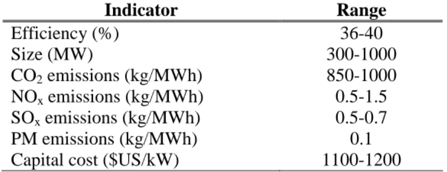
Nowadays, there are worldwide hundreds of gigawatts of subcritical pulverized coal combustion units (PCC), being among the oldest power plants in operation in the world (at least on average). PCC is an aged energy conversion technology that still dominates electric power generation from coal. PCC electric power is generated using the hot of coal combustion products to exchange heat with water vapor in a boiler. Then the superheated water vapor will produce work in a steam turbine. Due to thermodynamic (water as a working fluid), and metallurgic constraints, the efficiency of such plants is rather low. Modern coal-fired power plants achieve efficiency of about 38- 40% (based on the low heating value of the fuel) operating at 250-300 bar and at maximum temperature of 530-560°C, in table 3.1 are represented the current standard parameters of installed coal power plants.
86
Higher efficiencies can be achieved by further increasing water vapor parameters, as for supercritical boilers operating at pressures around 350 bar and temperatures of 700°C, where efficiency is expected to be not higher than 50% (LHV). An intrinsic handicap of the direct-fired boilers is the large temperature difference between the combustion gases and the working medium, which could be more than 1000ºC for a typical plant. Extremely irreversible heat exchange caused by this large temperature difference indicates the weakest point of this cycle. This potential energy would be better utilized in a gas turbine cycle, which can cover wider temperature range, from 1400 °C to 400 °C. Indicator Range Efficiency (%) 36-40 Size (MW) 300-1000 CO2 emissions (kg/MWh) 850-1000 NOx emissions (kg/MWh) 0.5-1.5 SOx emissions (kg/MWh) 0.5-0.7 PM emissions (kg/MWh) 0.1
Capital cost ($US/kW) 1100-1200
Table 3.1: Reference data for installed subcritical coal plants, with conventional
Sulphur control
But despite the main problems linked with the use of coal, as already been referred in chapter 1, there is a clearly perceptible tendency in the resurgence of coal as a major world fossil-fuel source used for energy production. As I have discussed in the section 1.2.1 The future of coal, many factors are encouraging this resurgence, in particular; the international coal prices that have had a strong track record of stability, especially in comparison with other fossil fuels (the price of oil hit record high of $78 per barrel on 10.7.2006 while the natural gas prices have also risen dramatically over the past year), where is expected that prices will be sustained at high levels or even will be increased. In this economic calculation potential high long term oil and gas prices
87
should be linked with the increasing risks of oil and gas purchases from unstable regions.
Within “business as usual” scenario, the PCC power plant attempts to be used to satisfy at least 85% of the total energy-growth demand expected for the next 25 years. During their lifetimes, these plants will release 140 Gt of CO2 into the atmosphere1. In order to cut back all these emissions, coal is proposed today to fuel up a plurality of advanced power plants with different levels of; thermal efficiencies, pollution emission, and different economic costs. Indeed, one of the most decisive targets for promoting clean coal technologies is a more efficient use of coal, and therefore a reduction of its pollutant emissions. The coal combustion produces structurally more pollutants that the other fossil fuel since it contains mainly carbon as reactive component (turning to CO2) and sulphur (turning to SOx) but very few hydrogen (turning to H2O). Additionally, coal-fired stations emit tonnes of ash through their chimneys, -the 80% of which is particulates smaller than 10 micrometers (PM10)-, HCl, mercury, nickel and lead. Moreover combustion produces NOx.
This can be addressed by enhancing the system efficiency and by using more effective emissions control technologies. Driven by these strategies, current developments in design of coal power plants is focused on higher steam parameters, incorporating gas turbines, low-emission burners, and better integrated emissions control systems. Indeed, any reasonable forecast about the future of coal-fired technology will confirm that there are not many perspectives for coal combustion technologies without the implementation of stronger emissions-reduction measures. In order to keep CO2 atmosphere concentration in the desired range, about the third part of the emissions expected in the next 50 years needs to be avoided1.
Hence, if CO2 emissions have to be drastically reduced by 60-80% and coal has to be use under such circumstances, an extensive separation of CO2 from the power plant process is on increasing importance as an option. However, as already examined in Chapter 2, any CO2 removal measure will unavoidably and significantly reduce the power plant efficiency and power output. Retrofit measures applied as end-of-the-pipe
88
devices to existing power plants will impair the performance to unacceptable levels, also requiring an enormous infrastructure and large investment costs. The most promising option is to reduce CO2 emissions by highly efficient power plant processes together with an appropriated integration into the process of pollutant separation technologies. In addition, essential problems of such strategies remain the disposal of the extracted CO2.
Nevertheless, carbon sequestration, -besides energy saving measures-, is the only credible alternative short term that would allow the continued used of fossil fuels without the threat of seriously altering Earth’s climate system.
The alternative to fitting carbon capture devices into pulverized coal-fired power plants not designed for it, is the use of integrated coal technologies. These is the occasion of advanced plants that provide a high integration of CO2 capture devices and an effective conversion of coal into electricity by employing the gas turbine cycle. Although, they are more expensive and less profitable than conventional plants, the CO2 can be captured significantly easier and cheaper. Thus, the perspectives for a correct use of coal as energy source are based on the success into the energy market of “clean coal technologies”, where good thermodynamic performance of the power plant are joined with a control of the pollutant emissions.
From the aforesaid considerations, the aim of this chapter is to discuss about the perspectives and challenges of the future of advanced clean coal technologies. A critical overview is provided about the thermodynamic features of the different plants together with the possibility of integrating emissions control devices.
In this chapter, the main low-emission coal-fired power plants alternatives to the conventional coal-fired plant are reviewed; as the ultra super critical (USC), the oxy-fuel, the Integrated Coal Gasification Combined Cycle (IGCC), the Externally-fired combined cycle (EFCC) and the Pressurized Fluidized Bed Combustion (PFBC). The development of these technologies would mach a sensible efficiency increase out of
89
coal conversion plants with an opportune control for CO2 emissions. In figure 3.1 are represented the main coal conversion technologies.
Coal
Combustion
Pulverized fuel Pulverized fuel
Atm. Press. AtmosphericAtmospheric PressurisedPressurised
USC-PF
USC-PF PCCPCC BFBCBFBC CFBCCFBC P-CFBCP-CFBC PFBCPFBC IGCCIGCC
Hybrid cycles Fluid beds Fluid beds Gasification Gasification Oxy-fuel Oxy-fuel
Steam turbine Gas turbine
EFCC EFCC
Steam cycles Gas cycles
Figure 3.1: Coal conversion technologies
3.2 Ultra-supercritical pressurized coal power plants USC
Ultra Supercritical stations (USC) represent the evolution of pulverized coal fired power plants2
. Till the beginning of the sixties a great technological evolution of PCC based on thermodynamic optimization has been accomplished. At the end of the fifties the first supercritical cycles were developed in U.S. The majority of these plants had not emissions controls equipments other that some removal systems. Since the sixties there have not been meaningful efficiency improvements, but growing attention to SOx and NOx emissions mitigation devices. Only in the nineties a renewed interest in the super critical technologies was carried out reaching the actual standard levels of 300 bar and 600ºC, see figure 3.2. Over 550 super critical PCC are available all over the world (about 150 in USA, over 100 in Japan and Russia, more than 30 in Germany for an amount of 300 GW)3.
90
With the term “ultra-super-critical” it is evidenced the overcoming of the limit conditions for the steam at the level of 245 bar/565 °C/565 ºC, to reach more advanced operating parameters towards to increase the pressure and turbine inlet temperature. Modern supercritical Rankine plants with reheat and regeneration operate at temperatures of 600ºC and pressures of 350 bar, obtaining efficiencies not higher than 48-49%4 240/540/565 300/580/600 300/600/610 300/640/650 170/540/540 (bar/ºC/ºC)
Figure 3.2: Thermodynamic evolution of PCC plants.
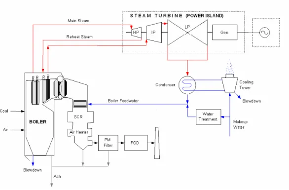
Nowadays, this technology incorporates several gas cleaning systems, new design of burners, new scheme of combustion in the boiler furnace and new design of steam super heaters, as illustrated in figure 3.3.
91
Figure 3.3: PCC power plant with cleaning systems.
Further developments of the USC technology are expected by raising the metallurgic limit with the use of high-temperature materials, or by choosing other working fluids. The super critical steam conditions have as long terms objective to reach a steam pressure level of the order of 350 bar and maximum steam temperature of 700 °C with the use of advanced material like inconel (AD700 USC plants). Theoretical analyses indicate the perspective of archiving net efficiencies of 50%. Moreover, in this category it is possible to consider the “end-of-the-pipe” emission control.
3.3 Integrated Gasification combined cycle (IGCC)
Since twenty years ago, the Integrated Gasifier Combined Cycle (IGCC) is considered the future of coal combustion technology, representing the main advanced alternative technology to conventional coal-fired power plants. IGCC permits good environmental performances and important features as modularity, repowering capability, and fuel flexibility.
92
An IGCC power plant is represented in figure 3.4, consisting of an air separation unit (ASU), including O2 compressor, oxygen-blown gasifier, particulates removal devices, gas clean up components (COS hydrolysis, H2S removal), CO2 removal equipment with a CO shift reactor and a CO2 capture device, gas-fired combined-cycle power plant and a control system for the integration among the units. In an IGCC power plant coal is gasified, cleaned-up and fed to the gas turbine, then, exhaust heat from the gas turbine is recovered in a steam boiler. First coal is converted into a synthetic gas (syngas: mostly CO and H2) by the gasification process. Then, CO and H2O are converted into CO2 and H2 in the water shift reactor system. While, Sulphur compounds, H2S, COS and CO2 can be simultaneously removed.
H2S, COS and CO2 removal can be accomplished by; wet gas cleaning by means of physical absorption (Retisol wash), or by membrane systems. A large part of the efficiency reduction is due to the CO shift (efficiency reduction is about 2.5 to 5 percentage points) the choice of the gas separation (efficiency reduction about 1 percentage point) does not have pronounced influence on the total efficiency reduction5. CO
2 removal from the shifted coal gas is advantageous compared to other processes, due to its small volume flow through the separation unit, its high total pressure (>20 bar), with a high partial pressure and concentration of CO2. Furthermore, the reduction gas turbine power output, because the separated CO2 is not expanded through the turbine achieves efficiency reduction of about 1 percentage point .
93
Figure 3.4: integrated gasification combined cycle power plant
The gasifier could archive temperatures of 1500°C, below the threshold where the thermal nitrogen oxides start to form (around 1600°C). The raw syngas drop out the gasifier at temperatures around 500-1400°C, and it must be treated in order to eliminate the solid particulate and the H2S. This is an essential step in the clean up process of the hot fuel gases, been required in order to fulfil the gas turbine inlet requirements.
The particle removal can be carried out at cold temperature, involving an undesirable cooling down of the raw syngas, like for example with cyclone technologies or electro-filters which working temperatures are around 150°C, or through hot gas filtration technologies which concerns new technologies where the process achieves temperatures closed to the gasifier outlet temperature, with almost no-energetic cost. Some of these technologies like hot gas filtration for particulates, are still in developing phase. Air Fuel ASU O2 CO2 to liquefied, transport and stored
HRSG To the Stack ST Air GT Energy Output C COS hydrolisis H2S removal CO shift Raw Syngas CO2 Capture G A S IF IE R Water from the condenser steam Syngas Particle removal Shaft power Cooling duty Energy required Energy Output Steam O2
94
IGCC is a high efficiency conversion technology that allows coal to benefit from gas turbine advanced, being up to 10% more efficient than conventional pulverized coal plants6. Anyway, the energy conversion grade is strongly subordinated to the gas turbine inlet temperature, to the degree of integration between the ASU and the gasification island as well as between the gasification and the power island and of the clean process temperatures.
Depending of the coal used, this technology achieves up to 98% SO2 removal and reduce NOx emissions to approximately 0.043kg/GJ without additional measures7
.IGCC power plants have specific CO2 emissions of 600g/kWh without economic penalties. But if CO2 emissions must be further reduced, IGCC technology can also offers very efficient options for CO2 removal. The highest net efficiencies of power plants with CO2 removal can theoretically be attained by IGCC with O2/CO2 firing (100% of CO2 removal) or by IGCC with CO shift and CO2 wash removing (around 90% of CO2 removal).
Plants with a CO shift reactor and physical washing where found to be the most appropriate options with respect to energy efficiency and economy. The overall efficiency only decreases by moderate 6% points with the need of an approximately 20% higher investment8. A high concentrated CO
2-rich stream is produced before the combustion, therefore, the CO2 capture process used is dealing with a lower gas volume, than in a post combustion capture process, with always required less investment cost and smaller capture devices.
The different technologies used for the CO2 capture can vary depending on the CO2 concentration and pressure at the syngas, from membranes technologies, cryogenic separation, or any other physical or chemical capture technology. IGCC systems operating at high pressure make CO2 capture by physical absorption feasible. Booras et al.9 have incorporated a two-stage Selexol process into the IGCC design for selective H2S removal and bulk CO2 removal. Similar was made by Herzog10. In both cases the use of a physical sorbent resulted in the capture step being much less energy-intensive than chemical sorbent.
95
Alternatively, calcium has been also used for high temperature CO2 capture in a dry regenerable sorbent. The carbonation reaction is employed in the CO2 acceptor process developed for coal gasification11. Accordingly, in fuel gasification processes the energy required for the gasification could be partially supplied by the exothermic carbonation reaction, where are employed fluidized bed reactor, gasifier and regenerator. Coal is gasified with steam in the gasifier, while limestone is calcined (decomposed to lime) in the regenerator. Thus, the heat for the gasification reaction is in some part provided by circulating calcined limestone (the acceptor) from the regenerator.
The capture CO2 reacts exothermically with the lime in the gasifier to form CaCO3, thus capturing CO2 in the gasifier12. Moreover the endothermic heat required to reverse the reaction in the regenerator, can be supplied by the combustion of residual char from the gasifier with air12
. This process allows the capture of CO2 in coal gasification by using residual energy of the plant. Therefore, the energy costs for the CO2 capture are very low compared to the cold temperature capture, (see chapter 2) avoiding stripper regeneration energy and the energy used to cool down the flue gas till the scrubbing cold temperature. Therefore, the high temperature absorption processes archive a higher grade of integration into the thermodynamic process of the energy systems13.
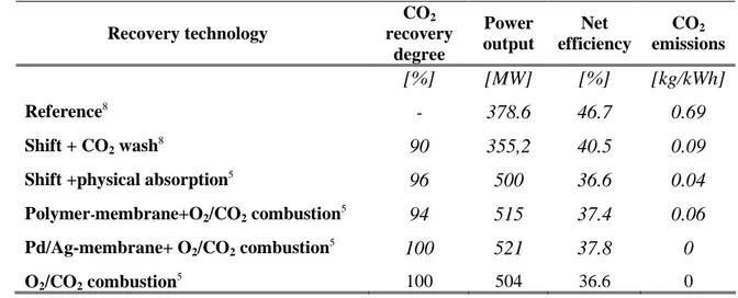
The current state of the art for IGCC plants reaches LHV efficiency close to 45%. But according to the results of different works in literature14;15,16 higher values can be reached in the mid term. Using, for example, hot-gas cleanup, the maximum temperature of the cycle can theoretically reach the level of the maximum temperature of the gas turbines. Table 3.2 compares data of IGCC with CO2 removal with a standard IGCC as reference case.
96 Recovery technology CO2 recovery degree Power output Net efficiency CO2 emissions [%] [MW] [%] [kg/kWh] Reference8 - 378.6 46.7 0.69 Shift + CO2 wash8 90 355,2 40.5 0.09
Shift +physical absorption5
96 500 36.6 0.04
Polymer-membrane+O2/CO2 combustion5 94 515 37.4 0.06
Pd/Ag-membrane+ O2/CO2 combustion5 100 521 37.8 0
O2/CO2 combustion5 100 504 36.6 0
Table3.2: Data of IGCC with CO2 removal. (Efficiency based on LHV)
IGCC can operate on a wide variation of calorific fuels values and composition, with great potential for using locally available medium calorific fuels values as gases from municipal solid waste or biomass, creating a considerable challenge for gas turbine manufactures and combustion engineers in the industrial gas turbine.
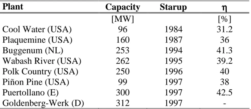
Table 3.3 shows a number of commercial scale coal-based IGCC power plants. Among them of particular interest are the 253 MWe IGCC power plant of Buggenum (the Netherlands), the 252 MWe IGCC of Wabash River (Indiana-USA), the 250 MWe IGCC of Polk County (Florida-USA) and the 318 MWe IGCC of Puertollano (Spain) showed in figure 3.5.
97
Plant Capacity Starup ηηηη
[MW] [%]
Cool Water (USA) 96 1984 31.2
Plaquemine (USA) 160 1987 36
Buggenum (NL) 253 1994 41.3
Wabash River (USA) 262 1995 39.2
Polk Country (USA) 250 1996 40
Piñon Pine (USA) 99 1997 38
Puertollano (E) 300 1997 42.5
Goldenberg-Werk (D) 312 1997 -
Table 3.3: Commercial scale coal-fired IGCC power plant16,17.
300 MW Wabash (Indiana)
250 MW-Buggenum (Netherlands) 250-MW Tampa El. (Florida)
300 MW Puertollano (Spain) 300 MW Wabash (Indiana)
250 MW-Buggenum (Netherlands) 250-MW Tampa El. (Florida)
300 MW Puertollano (Spain)
Figure 3.5: Existing Coal based IGCC power plants
The future of these plants should aim to prove the technical and economic feasibility of a commercial-scale IGCC plant fitted with CO2 capture technology. The U.S.
98
“FutureGen” initiative is a $1-billon public-private partnership to design, to build, and to operate a coal-fuelled zero-emissions power plant by 2015. While in Europe the German company RWE Power has recently announced that it will invest €1 billion in the construction of a 450 MW IGCC plant in Germany. The plant fully equipped for CO2 capture, could became operating in 2014.
3.3.1 The modular perspective of IGCC
One of the keys to a successful of IGCC Power Plant is the fact that it can be designed to be modular, see figure 3.6; to take advantage of local feedstock to minimize costs, and to produce products for which a demand exists and that can be marketed. The modules will be selected and implemented based on the two factors; input and output. The facilities produce mostly chemicals (37%), gas (36%) or power (19%). In terms of feedstock, some of them are solid feedstock based (coal and petroleum coke), and others are refinery high sulphur heavy oil based. Only a few numbers of them are based on coal.
Among other methods, fuels would be converted by gasification to a synthesis gas from which potential pollutants would be transformed into valuable byproducts. At the extremes of the concept it has even been speculated that, in some environments, the optimum output would be entirely products other than power. For example, those outputs, whether upgraded fuels for transportation purposes, or chemicals for sale on the open market, or whatever, would then be sold to generate the funds in order to purchase power and heat from a secondary source. In this sense an IGCC could places the chemical plant in the front end of plant, in contrast, a conventional coal plant is less efficient because it places a chemical plant at the back end, attempting to capture pollutants after combustion where are much diluted and as a consequence they are more difficult to be captures.
For this reason IGCC technology provides great promise for the future due to the flexible feedstock, process options and products and opens new markets for coal
(syn-99
fuels, chemicals, fertilizers). It also provides the only feasible bridge from coal to hydrogen (directly converts coal to hydrogen). But in the meantime new barriers are growing to deployment of IGCC. The first is the power Industry Culture. IGCC is a chemical plant and power companies do not like chemical units. Moreover there are much technical and financial risks and finally power companies do not understand why to construct an IGCC when it is possible to get a permit for a conventional coal plant.
Fuel Gas Turbine Combined Cycle O2 Syngas H2 and CO Coal Gasifier ASU Sulfur, PM Gas Cleanup By-products 37% Auxiliary products Power 19% Gas 36%
Figure 3.6: Modular schema for a Integrated gasifier Combined cycle
3.4. Pressurize fluid bed combustion (PFBC)
Pressurized fluidized bed combustion represents a straightforward evolution of the circulating fluidized bed combustion, which gained great attention from the seventies. It permits basically the possibility of a strong reduction of SO2 and NOx emissions with respect to pulverized coal power plants. From the thermodynamic point of view, the main benefit obtained from PFBC consists on the possibility of increasing the plant efficiency, coupling a Rankine cycle with a gas turbine.
One of the main attractive factors of fluidized bed combustion is due largely to the technology's fuel flexibility. The controlled combustion permits almost any
100
combustible material. From coal to municipal wastes can be burned with the capability of meeting SO2 and NOx emission standards without the need for expensive add-on controls.
The conventional PFBC system used a sorbent such a limestone or dolomite to capture sulfur released by the combustion of coal. The mixing action of the fluidized bed brings the flue gas in contact with the sulphur-sorbent chemical, accordingly more than 95% of the sulphur pollutants in coal can be captured inside the boiler by the sorbent. Hence, it is possible to achieve low SO2 emission levels without additional sulphur removal equipments, even if high sulphur coal is used. Moreover, burning occurs at 760-930°C, well below the 1370°C needed to generate nitrogen oxide pollutants. So, the NOx formed in the bed is less than in conventional combustors, which operated at higher temperatures. For all the circulated fluid bed combustors, further suppression of NOx formation can be accomplished by air staging with less impact on combustion efficiency than in pulverized coal furnaces.
Fluidization means that the solid coal particulates are suspend and mixed with jets of air and sorbent and burned during combustion at about 860ºC, which converts the mixture into a suspension of red-hot particles that flow like a fluid. Elevates pressures and temperatures produces a high-pressure gas stream that can be driven direct to the gas turbine. There are basically two versions of PFBC technologies approaching the market: (i) the bubbling-bed concept and (ii) the circulating fluidized-bed concept. A major efficiency enhancing measure for 2nd generation PFBC systems, see figure 3.7, is the second concept integrated with a pressurized carbonizer (gasifier) in order to process the feed coal into fuel gas and char. The PFBC burns the char to produce steam and to heat combustion air for the gas turbine. The fuel gas from the carbonizer burns in a topping combustor linked to a gas turbine, heating the gases to the combustion turbine‘s rated firing temperature. Heat is recovered from the gas turbine exhaust in order to produce steam, which is used to drive a conventional steam turbine, resulting in a higher overall efficiency for the combined cycle power output.
101
Figure 3.7: Pressurized fluid bed Combustion
The topping combustor must exhibit flame stability in combusting low-energy gases and low-NOx emission characteristics. To take maximum advantage of the increasingly efficient commercial gas turbines, the high-energy gas leaving the topping combustor must be nearly free of particulate matter and alkali/sulphur content. Also, releases to the environment from the pressurized fluid bed combustion system must be essentially free of mercury, a soon-to-be regulated hazardous air pollutant.
For the reduction of CO2 emissions, CO2 capture technologies can be used before the topping combustion, reducing the volume gas to be treated and therefore increasing the CO2 partial pressure, providing an easier way for the CO2 capture, which reduces the size of the capture devices, decreasing equipment costs18.
The resulting process is similar to a combined cycle, but contrary to what occurs in those plants, the steam turbine generates the high percentage of the power (until the 80%). Today’s PFBC plants operate with an efficiency of 37-42% (LHV), and the next
Air GT Energy Output C HRSG HRSG Energy Output ash stack G as if ie r C ar b on iz e r G as C le an U p Topping Combustor Char PFBC Char Steam Hot flue gas
Ash Air Sulphur sorbent Coal Air ST ST Energy required
102
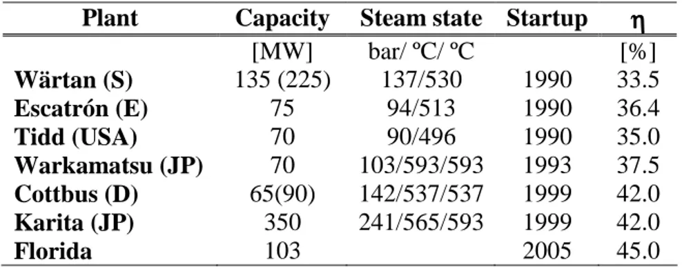
generation are expected to reach a level of 40-46%19. Just as the IGCC technology, pressurized bed combustion is also characterized by its complexity and high capital costs. Table 3.4 gives an overview of PFBC commercial scale power plants.
Plant Capacity Steam state Startup ηηηη
[MW] bar/ ºC/ ºC [%] Wärtan (S) 135 (225) 137/530 1990 33.5 Escatrón (E) 75 94/513 1990 36.4 Tidd (USA) 70 90/496 1990 35.0 Warkamatsu (JP) 70 103/593/593 1993 37.5 Cottbus (D) 65(90) 142/537/537 1999 42.0 Karita (JP) 350 241/565/593 1999 42.0 Florida 103 2005 45.0
Table 3.4: Commercial scale PFBC power plants17
Due to its attractive environmental performance and high fuel flexibility, the PFBC has been intensively studied for implementation in the coal-power generation in the last decade20,21,22..
3.5. Oxy-fuel combustion power plants (O
2/CO
2)
Combustion of fuel with O2 instead of air results in a free-nitrogen flue gas consisting of mainly CO2 (about 90% on dry basis) water and excess of O2, and in a minor amount of non-condensable gases. The oxygen-combustion considerably reduces the heat losses that take place in the boiler, since there is no bulk nitrogen to be heat and cool down again in the combustion process. It would also reduce energy losses for gas cleaning, making possible to control and optimize the combustion process.
Combustion with pure O2 reaches combustion temperature of about 3500ºC, which is far too high for typical power plant materials. The combustion temperature is controlled to about 1900ºC by a portion of the flue gas recycled back to the combustion chamber. The remaining part of the flue gas, containing mainly CO2and
103
vapor, is very suited to CO2 capture without requiring much energy consumption and costly infrastructure.
The reason for recycled a fraction of the exhaust gases to the boiler, in the oxy-fuel recycled system, is in order to moderate the flame temperature, including combustion at nearly stoichiometric conditions and to establish adequate flue gas flow rates through the boiler. Increased pressure and decreased flame temperature favour CO2 production and inhibit the back reaction of CO to C. This offers also the possibility for minimizing the generation of NOx, whichis also controlled by this created uniform temperature distribution of the flame. This will reduce significantly the boiler size, which means that the efficiency loss due to thermal radiation to the environment will be reduce, as well as the electric power requirements for the flue gas recirculation fans. A significant reduction of the boiler size will also lead to a reduction in boiler investment cost. The amount of recirculation is limited by the combustor.
In principle, this technology can be applied to steam cycle, oxy-fuel indirect heating and to gas turbine cycle, oxy-fuel direct heating.
When applied to gas turbine cycle this technology deviates from standard gas turbine mainly due to a different working fluid composition. The hot gas is expanded in a modified gas turbine producing power. A major parts of the CO2-rich exhaust gas, acting as a working fluid, is cooled down to provide heat for a steam cycle and recycled back to the compressor, compressed and fed into the combustor. This will control the gas turbine inlet temperature in order to keep it at permissive values. Thus, there is no need for de-NOx equipment. For this propose, only natural gas and syngas can be used as fuels.
Oxy-Fuel (O2/CO2) recycle combustion power plant can be also a highly interesting integrated option for coal-based power generation with CO2 capture. The technology can be retrofitted basically to any conventional combustion process; as to typical steam turbine coal-fired plant, where the CO2-rich exhaust gas is recycled back to the boiler23,24. In contrast to IGCC or PFBC, oxy-fuel recycled technology requires fewer unit operations being intrinsically less complex technology.
104
Oxy-fuel combustion for coal can take advantage of ongoing development to increase efficiency of conventional steam power plants, with the same engineering challenges, including the areas of combustion and heat transfer, boiler design, boiler materials, and flue gas processing.
Further specific challenges for oxy-fuel technologies will include the reduction of energy consumption for oxygen production, the recovery of low temperature heat in flue gas and CO2 product requirements (including effect on transport and storage system).
In figure 3.8 are shown the main mass flows, thermal energy, energy consumption and electric power output for a O2/CO2 recycle combustion process.
.
Figure 3.8: O2/CO2 recycle combustion coal-based fuel plant with the main internal
energy consumption data
The largest parasitic loss for oxy-fuel systems resides in the air separation unit, therefore, improvements to air separation technology are specially significant to oxy-fuel processes. In general, studies of the oxy-oxy-fuel technology assume that the oxygen is produced in a standard cryogenic air separation unit (Cryo-ASU). Although liquid membranes, pressure swing absorption (PSA) and chemical looping are sometimes mentioned for future concepts25, cryo-ASU is the only available large scale technology
Condensing Water CO2 Cooler /condenser Air Fuel
Net power output
ASU Recycled CO2/H20 H2O O2 Power Steam Turbine Process Low tempetature heat No-condensable gases Low tempetature heat Boiler CO2 to transport and stored Internal power consumption Compression power Cooling power Refrigerant power Low tempetature heat N2 Steam Particle removal Sulphur removal H2O CO2
105
for oxygen separation from air at the present26. The electric power consumption of a Cryo-ASU necessary for air compression/separation and cooling duty may amount around 20% of the plant net power output27,23, which of course reduces significantly the plant efficiency.
The minimum energy necessary to separate air can be calculated to approximately 0,06 kWh/kg O2. In gas separation the actual energy consumption is considerably higher, and it will vary depending of the product purities, in literature are assumed values for oxygen generated at atmospheric pressure around 0.25 kWh/kg of 93-95% O2 (or 0.89 MJ/ kg CO2)28. Advances in oxygen separation are expected to reduce this power to 0.16 kWh/kg O2 when the ion transport membrane (ITM) technology matures28. This will increase the efficiency of the oxygen plant by 37% and reduce the capital cost by 35%28
.
Commercially available cryogenic air separation units are capable for providing oxygen at up to 99.5% purity; however the cost begins to escalate as the purity exceeds 95%.
The CO2 concentration in the flue gases reaches values up to 95% (by vol.), thereby facilitating CO2 recovery. Indeed, it is the water and no-condensable gases that have to be removed from the CO2-rich stream, with little or no further treatment (e.g. condensation technology). Almost all the CO2 can be captured, and if deemed deliverable, there may be possible for co-capture of other pollutants, mainly sulphur oxide, where the absence of bulk nitrogen in the flue gas means that the equipments for flue gas desulphurization and nitrogen oxide removal will have smaller volume, and thus be cheaper. Furthermore, acid water-soluble pollutants will be dissolved in the water condensed from the process and not emitted to the atmosphere, which may be much recommended for coal- fired boilers. The cleaning of the condensed water can be done with methods already commercially available. Thus, the energy consumption for the CO2 recovery is fundamentally the CO2 compression, which represents around the 5% of the net power output of the plant. Moreover refrigeration energy for the CO2 liquefaction and transport should be included.
106
Altogether, the O2/CO2 recycle combustion power plant may offer a possibility for zero-emission not only for CO2 but also for other harmful substances. Corrosion-related issues must therefore be carefully handled for the flue gas pathways and for the flue gas condenser.
The main opportunities with O2/CO2 recycled combustion of coal in new plants are to reach high energy-efficient integration of O2 production and flue gas cleaning. Also improvement in the field of advanced steam technologies data, linked to the development of material for extremely high pressure and temperature in combination of boiler and turbine design are necessary in order to design a plant that has sufficiently high conversion efficiency and low total cost of electricity so that it is interesting to build.
3.6 Externally-Fired Combined Cycle (EFCC)
A system based on a coal-fired steam boiler integrated with a gas turbine, has been proposed in literature29,30,31
. In such a plant, known as the externally fired combined cycle (EFCC), compressed air is heated indirectly in a high temperature heat exchanger located in the coal furnace, see figure. 3.9. The hot air is then expanded in a turbine, after expansion, air can be partly redirected to the furnace to supply preheated air for combustion, and/or passed to a heat recovery steam generator.
Steam produced in the boiler generates additional power in a steam turbine; where the exclusion of coal combustion products from the gas turbine avoids the expense of hot gas clean up and corrosion of turbine blades by coal ash. In addition, an abatement device for CO2, NOX or SO2 can be easily included after the heat exchanger located in the steam turbine cycle, before the exhaust gases from the coal and natural gas combustion escape to the atmosphere. This equipment will require a considerable amount of energy consumption that can be provide by the steam turbine.
107
Figure 3.9: Externally fired combined cycle
In order to obtain a high level of efficiency the air entering the gas turbine should have a temperature close to the turbine inlet temperature, which can be as high as 1300° C for modern turbines. Such temperatures can be accomplished by the use of ceramic heat exchangers, or alternatively, by supplementary firing of a premium fuel, such as natural gas, in the air flow. The overall energy efficiency was found to be comparable with those of the IGCC or PFBC systems 32.
One of the main attractive of this type of plants is the high versatility towards the primary fuel used, where coal can be easy substituted for any other low calorific value such a biomass or municipal waste, mainly because avoids the primary fuel combustion gases entering the turbo-machinery. Another advantage of the externally fired cycles pointed out in heat utilization. Although air has a lower specific heat than steam, it does not require high pressures at high temperatures. Heat exchange between air and the flue gases occurs in the gaseous state, so the average temperature difference in the heat exchangers is smaller than in the case of steam.
The high temperature heat exchanger is the most critical component of the system and is not yet sufficiently proven technology. Depending on the turbine inlet temperature and other parameters, an EFCC plant can reach efficiencies of 40-49% (LHV)29.
108
3.7 Conclusions
In the foreseeable future, coal will likely remain the most important fossil fuel for electricity production. Thus, the industry is motivated by the urgent need of cleaner advanced technologies for electricity generation using coal as fuel. Different projects related with clean coal technologies for power generation are undertaken worldwide, particularly in the United States, in Europe, and in Asia.
Primary focus of these efforts is to develop advanced coal plants, see figure 3.10, leaving steam-based systems (33-35% average efficiency) and going towards higher efficiency levels. In this efficiency pathway, new technologies are paving the way for coal plants that could achieve approximately 55% efficiency in the future, compared to today’s fleet average of 33%.
Figure 3.10: Net station efficiency (%) of main fossil-fuel power plants, based on ISO
ambient conditions and 0.04 bar steam-condensing pressure8.
These advanced plants have to include also innovative concepts for pollutants control. Good successes have been observed in controlling PM, NOx and SOx emissions,
109
including more economic and eco-compatible solutions than can be retrofitted to the existing base load coal-fired power generating capacity. Advanced, low-cost emissions control systems have been successfully demonstrated and deployed in multiple plants. However difficulties for the maintenance of standards during operating life of the plant have been detected. Major efforts include also the problems linked to the by-product utilization (ammonia, urea, limestone, and gypsum), low-NOx combustion, mercury control, fine particulate control, water management, analysis on mercury formation during combustion and during the evolution of the treatments.
Moreover, since coal is not a uniform source due to its extremely variable composition; these technologies have problems to reach a standardization that can be very sensitive to the fuel use.
Regarding the future, ultra supercritical pulverised coal firing plants are likely to make serious contributions in a mid-term scenario to the energy sector. Research lines will involve new advanced materials for high temperature and pressure steam. Considering emissions, the advanced technologies have to compete with the available Pulverized Coal Combustion (PCC) plants, characterized by a level of CO2 emission in the range between 850 and 900 g/kWh. The level of 780 g/kWh can be reached with 580°C-Supercritical steam plants, while the barrier of 700 g/kWh can be broken with the 700 °C-USC plants17
.
For IGCC and PFBC the latest advances in gas turbine have helped bring the overall efficiency of a coal-fueled power plant to 41-46% (LHV). These technologies are characterized by large fuel flexibility - almost any combustible material, from coal to municipal waste-, can be burned. IGCC and PFBC attain also great capability of meeting sulphur dioxide and nitrogen oxide emission standards without the need for expensive add-on controls. The advantage with respect to the USC plants appears more clearly analyzing the SO2 emission, which can be reduced from the level of about 2 g/kWh to 0.2 g/kWh, with IGCC and PFBC power plants17 CO
110
700 g/kWh can be obtained both with PFBC and with IGCC8. However, their high level of complexity leads to lower reliability and higher equipment and maintenance costs.
Notwithstanding some successful experiments performed especially for IGCC, the low number of operating plants showed a lot of problems, mostly concerning the availability. In the meantime the renewed interest in the super critical power plants made quite less attractive investments on PFBC, so far this technology has too much operation problems and no great advantages. Anyway, IGCC has become a interest solution for the petrochemical industry. More than 120 plants with more than 380 gasifiers are in operation in 2004.
Relating to the introduction of CO2 emissions capture and storage technologies some promising strategies are available but uncertainty about general strategy is apparent. There are still many technologies in developing phase. Even if none of these technologies will be able to fully achieve the efficiency, environmental, and cost goals that are needed in the next decades, they embody the basic advanced technologies for the power plants in the farther future.
Moreover, the choice among coal advance technologies depends on energy policy, fuel type and availability, technology maturity and reliability, including cost, efficiency and environmental performance and local circumstances.
References
1 Schiermeier, Q., 2006, “The hundred billion tonne challenge” nature vol. 44, pp. 620-623
2 Bugge, J., Kjaer, S., 2003, “High efficiency coal fired power plants development and perspectives”, Proceedings of ECOS 2003, Copenhagen, pp. 1349-1354.
3Luby P., 2003, “Supercritical Systems”, Modern Power Systems, pp. 27-32. 4
Rogers, G.F.C. and Mayhew, Y.R., 1992, “Engineering Thermodynamics, Work and HeatTransfer”, Longman Scientific & Technical, Essex, UK.
111
5 Hendriks, C., 1994, “Carbon dioxide removal from coal-fired `power plants” Kluwer Academic publishers. Norwell, MA.
6Lozza G., Chiesa P., De Vita L., 1996, “Combined-cycle power stations using clean-coal technologies: thermodynamic analysis of full gasification versus fluidized bed combustion with partial gasification”, Journal of Engineering for Gas Turbines and Power, Transaction of the ASME.
7 DOE, 1999.” Coal & Power Systems”. Tech. Rep., Office of Fossil Energy, U. S. Department of Energy.
8
Pruschek, R., Goettlicher, G., Oeljeklaus, G., Haupt, G., Zimmermann, G., 1998, “IGCC Concepts as best option for CO2 reduction in fossil-fired power stations” Power-Gen Europe’98 Milan, June.
9 Booras, G.S., Smelser, .C., 1991, “An engineering and economic evaluation of CO2 removal from fossil-fuel-fired power plants” Energy 16, p. 1295
10 Herzog, H., 1999, “Introduction to CO
2 separation and capture technologies” U.S. Departament of energy workshop, Houston, TX.
11 Curran, G.P., Fink, C.E., Gorin, E., 1967, “CO
2 acceptor gasification process: Studies of acceptor properties,” Advances in chemistry. In Fuel gasification, 69th ed. Schorda, F.C., Ed.; ACS. Pp. 141-165 12
White, C.M., Strazisar, B.R., Granite, E.J., Hoffman, J.S., 2003, Critical review “Separation and capture of CO2 from large stationary sources and sequestration in geological Formations-Coalbeds and deep Saline aquifers” Air & waste manage. Assoc. vol 53, ISSN 1047-2389
13 Silaban, A., and Harrison, D.P., 1995, “High temperature capture of carbon dioxin, Characteristics of the reversible reaction between CaO(s) and CO2 (g)”, Chem. Eng. Comm. 137-177
14 Maude, C., 1993, “Advanced Power Generation – A Comparative Study of Design Options for Coal”, IEA Coal Research, London.
15
Stambler, I., 1996, “Progress in IGCC and Advanced Cycles” Outlined at EPRI Meeting, Gas Turbine World, January-February
16 Pruschek, R., Oeljeklaus, G., Brand, V., Haupt, G., Zimmermann, G., 1994, “GuD Power plant with integrated coal gasification CO shift reactor and CO2 washing” Power Gen Europe, Cologne, Germany. 17 Bernero, Y.C., 2001, “Comparative evaluation of Advanced Coal-Based Power plants” PhD thesis 18 Salvador, C., Lu, D., Anthony, E.J., Abanades, J.C., 2003, “Enhancement of CaO for CO
2 capture in a FBC environment” Chem. Eng. J. 96, pp. 187-195
19 Almhem, P., and Lofe, J.J., 1996, “PFBC Power Plants: A Competitive Alternative”, Power-Gen International Conference, Orlando, Florida, December 4-6.
112
20DOE, 1989. “Conceptual Design and Optimization of a Second generation Pressurized Fluidized Bed Combustion Plant”. Tech. Rep. DOE/MC/21023-2825, Office of Fossil Energy, U. S. Department of Energy
21 Buchanan, T. L., Goldstein, H. N., Harvey, L. E., Rubow, L. N. & Zaharchuk, R., 1994. „Clean Coal Reference Plants: Pressurized Fluid Bed Combustor”. Tech. Rep. 3009, Gilbert/Commonwealth, Inc. 22White, J. S., Getty, R. T. & Torpey, M. R., April, 1995. “Commercial Second-Generation PFBC Plant “Transient Model Task 15. Tech. Rep. DE96000570, Office of Fossil Energy, U. S. Department of Energy.
23 Jordal, K., Anheden, m., Yan, J., Stroemberg, L., “Oxyfuel combustion for coal-fired power generation with CO2 capture – opportunities and challenges“ Vattenfall Utveckling AB, 162 87 Stockholm, Sweden.
24 Singh, D.J., Croiset, E., Douglas, P.L., Douglas, M.A.,2003, “Thechno-economic study of CO 2
capture from an existing coal fired power plant: MEA scrubbing vs. O2/CO2 recycle combustion”, energy conversion management; 44, pp. 3073-3091.
25
Zeng, Y., Acharya, D.R:, Tamhankar, S.S., Ramprasad, N., Ramachandran, R., Fitch, F.R., Maclean, D.L., Lin, J.Y.S., Clarke, R.H., 2003, “Oxy-fuel combustion process”US patent Application publication No US 2003/0138747 Al.
26 Yuang, R.T., 1997, “Gas separation by Adsorption processes”, Butterworth’s, 1997
27 Andersson, Klas and Peter Maksinen, 2002 “Process Evaluation of CO2 Free Combustion in an O2/CO2 Power Plant”, pp 8-17, Masters Thesis, Report T2002-258, Department of Energy Conversion, School of Mechanical Engineering, Chalmers University of Technology, Goteborg, Sweden.
28 Armstrong, P., Sorensen, J., Foster, T., 2003, “ITM Oxygen: An Enabler for IGCC,” Gasification Technologies 2003, San Francisco, CA, USA.
29 Consonni, S., Macchi, E, and Farina, F., 1996, “Externally-Fired Combined Cycles (EFCC). Part A: Thermodynamics and Technological Issues” , ASME Paper 96-GT-92.
30 Consonni, S. and Macchi, E., 1996 “Externally-Fired Combined Cycles (EFCC). Part B: Alternative Configurations and Cost Projections”, ASME Paper 96-GT-93.
31 Eidensten, L., Yan, J., and Svedberg, G., 1994 “Biomass Externally Fired Gas Turbine Cogeneration”, ASME Paper 94-GT-345.
32 Korobitsyn, M.A., 1998 “New and advanced energy conversion technologies. Analysis of cogeneration, combined cycle and integrated cycled”, ISBN 90 365 11070, Printed by Febodruk BV, Enschede.