Activities in Support to the Assessment of Steam Generator Bayonet Tubes, for GEN-IV Applications
Descrittori
Tipologia del documento: Collocazione contrattuale:
Rapporto Tecnico
Accordo di programma ENEA-MSE: tema di ricerca "Nuovo nucleare da fissione"
Generation IV Reactors
Termoidraulica dei reattori nucleari Tecnologia del piombo
Trasmissione del calore
Argomenti trattati:
Sommario
The overall activity is aimed to verify the feasibility of the superheated steam double wall once through
bayonet type steam generation. The work and the relative experimental campaigns will be focused on the single tube evaluation. It spans over three years. The mainphases ofthe experimental campaigns are:
-Individuate a candidate material as gapfiller for the bayonet tube.
-Verify the single tube performance inrepresentative operating conditions.
This report is the result of a collaboration between UNIPI-UNIROMA 1and ENEA. It issubdivided in seven sections. The first one points out the objectives and the framework of the activity. Section two describes the ALFRED SG and points out the results ofthe screening of candidate insulating materials to be placed in the
bayonet tube, between the descendent feedwater and the superheated steam riser. In section three, the
detailed assessment of the single tube performance by means of RELAP-5 is reported. Systematic comparison with the ANSALDO calculations are included. Section four focuses on the thermal hydraulic conceptual design of the heating power system of the Heavy liquid mEtal - pRessurized water cOoled tube facility (HERO). The section points out the geometry of a facility capable to test one 1:1bayonet tube of ALFRED. RELAP-5 and FLUENT calculations are presented in this section. The preliminary PIO of HERO
is analyzed in section five. The status of advance ofthe Tubes for Powders facility (TxP) isdiscussed in the sixth section. Summary and conclusions are presented in the last section..
Note
Autori:
D. Rozzia, D.Martelli, N. Forgione (UNIP!)
M. Moretti, A. Naviglio, D.Vitale Di Maio (UNIROMAl)
A. Del Nevo, M. Tarantino (ENEA)
Copia n. In carico a:
NOME NOME
1
FIRMA
o
EMISSIONE 18/0912012 I----~l\ ••D. Ro-.../-r.--J."J.zz-L-,,Dia-+-....,<:,.+'y
--/J---.
/.Gaggini"-_-=-=--+--M--.vTa--'"A~.1~J11A1~tir9--FIRMA V'Wl
r
-
1 rt/
at
I
'i...---.' /V Vv
VCO~ALIDA
Acknowledgments
The authors express their gratitude to Mr. Gino Venturi who allows the design of the TxP Facility. We acknowledge Alessandro Ventura who provides support to the assembling of the TxP Facility and to the preliminary testing of candidate powders.
We acknowledge Marco Gregorini for the fruitful recommendations that allow the development of the Steam Generator Bayonet Tube RELAP-5 improved input deck.
Abstract
One of the most promising Generation IV concepts is the Lead cooled Fast Reactor (LFR). The use of lead as primary coolant appears motivated by several reasons (low moderation, thermal properties, etc…), nevertheless, it still has several limitations that require further investigations. The actual configuration of LFR pointed out in the framework of the ELSY and LEADER projects deals with the compact pool type reactor in which the steam generators (SG) are located inside the reactor tank. In this scenario, the steam generator design plays an important role because one of the most impacting incidents is the Steam Generator Tube Rupture (SGTR) that may propagate to the near-bough tubes. The SG proposed in ELSY is the flat spirals type. In the framework of the EU project LEADER, an innovative configuration of SG has been proposed: the super-heated steam double wall once through bayonet type. This conceptual design was studied since 60’ for Sodium Reactor application. An example of facility that operates with this concept is CIRCE (ENEA Brasimone), nevertheless the application is limited to the heat exchange function.
The single tube vertical unit consists of three concentric tubes. Starting from the smallest one, the water crosses in down-flow the tube and heats-up. At the end of this tube, the water enters the second concentric tube in up-flow where it starts to boil because of the heat exchange with the liquid lead that flows in counter-current at the tube outer surface. The tube design allows the achievement of super-heated steam. The liquid lead is not in direct contact with the second tube. A third concentric tube, that creates an annulus, separates it from the steam-water sides. The study of this configuration is motivated by safety improvement. Indeed, it allows the double physical separation between lead and water sides by means of an intermediate gap. Thus, the probability of vessel pressurization by water-lead contact results reduced. Furthermore, by means of gap pressurization (with Helium), a leakage check system should be introduced in order to prevent incident scenarios. On the other hands, the monitor-ability of the pressurized gap has to be demonstrated and the thermal efficiency has to be improved.
The overall activity is aimed to study the bayonet tube performance. The work and the relative experimental campaigns will be focused on the single tube evaluation. It spans over three years. The main phases of the experimental campaigns are:
• Individuate and test a candidate material as gap filler in order to increase the thermal
efficiency;
• Verify the single tube performance in representative operating conditions by means of
computational tools and experimental tests.
This report has been carried out as a collaboration among UNIPI, UNIROMA1 and ENEA. It is subdivided in seven sections. The first one points out the objectives and the framework of the
activity. Section two describes the ALFRED SG and points out the results of the screening of candidate insulating materials to be placed in the bayonet tube, between the descendent feedwater and the superheated steam riser. In section three, the detailed assessment of the single tube performance by means of RELAP-5 is reported. Systematic comparison with the ANSALDO calculations are included. Section four focuses on the thermal-hydraulic conceptual design of the heating power system of the Heavy liquid mEtal – pRessurized water cOoled tube facility (HERO). RELAP-5 and FLUENT calculations are presented in this section. The preliminary PID of HERO is analyzed in section five. The status of advance of the Tubes for Powders facility (TxP) is discussed in the sixth section. Summary and conclusions are presented in the last section.
CONTENTS
A
CKNOWLEDGMENTS... 3
A
BSTRACT... 3
A
BBREVIATIONS... 7
L
IST OF FIGURES... 9
L
IST OF TABLES... 13
1
I
NTRODUCTION... 15
1.1
Framework and Objective of the Activity ... 15
1.2
Structure of the report ... 16
2
ALFRED
S
TEAMG
ENERATORB
AYONETT
UBE... 19
2.1
Description ... 19
2.2
Identification of Potential Insulators for the Inner Tube ... 22
3
A
SSESSMENT OF THESG
B
AYONETT
UBE BYM
EANS OFRELAP-5 ... 27
3.1
Development of the Reference Nodalization ... 28
3.2
Assessment of the Reference Nodalization ... 31
3.2.1 Assessment of the Hydrodynamic Components... 32
3.2.2 Assessment of the Heat Structures ... 35
3.2.3 Assessment of 2ϕ Dynamics in the Water Steam Side ... 40
3.3
Sensitivity Analyses ... 45
3.4
Development of the Improved Input Deck ... 46
3.4.1 Assessment of the Hydrodynamic Components... 47
3.4.2 Assessment of the Heat Structures ... 50
3.4.3 Assessment of 2ϕ Dynamics in the Water Steam Side ... 55
4
T
HERMALH
YDRAULICC
ONCEPTUALD
ESIGN OFHERO ... 59
4.1
Objectives of the HERO Facility and Potential Heating Power System ... 59
4.2
Calculations in Support to the TH Design of HERO by RELAP-5 ... 62
4.2.1 Initial Input Deck Documentation ... 62
4.2.2 Identification of the Potential Geometries of HERO ... 67
4.2.3 Assessment of the HERO Reference Configuration ... 70
4.2.4 Comparison Between Selected Lead Levels and SGBT ... 75
4.3.1 Preliminary 2D Axial-Symmetric Simulations ... 80
4.3.2 Preliminary 3D Simulations ... 84
5
P
RELIMINARYP
IPING ANDI
NSTRUMENTATIOND
IAGRAM OFHERO ... 95
5.1
Preliminary PID of the Heating Power System ... 95
5.2
Preliminary PID of the Pressurized Cooling Water System ... 97
6
S
TATUS OF THET
XP
F
ACILITY... 99
6.1
Description of TxP ... 99
6.2
Status of TxP ... 101
6.3
Activities in Support to the Planning of the TxP Experimental Campaigns103
6.3.1 Description of the Experiments ... 1036.3.2 Powders Pre-Characterization ... 105
6.3.3 Main Achievements from the Experiments ... 107
7
C
ONCLUSIONS... 111
Abbreviations
A Accepted
Al-N Aluminum Nitride
ALFRED Advanced Lead Fast Reactor European Demonstrator
Ar Argon
CDT Central Design Team
CFD Computational Fluid Dynamics
CHF Critical Heat Flux
CIRCE CIRColazione Eutettico
Cu Copper
CR Centro di Ricerca
DHR Decay Heat Removal system
DIMNP Dipartimento di Ingegneria Meccanica, Nucleare e della Produzione
DP Diamond Powder
ELFR European Lead cooled Fast Reactor
ELSY European Lead cooled SYstem
ENEA Agenzia nazionale per le nuove tecnologie, l’energia, e lo sviluppo economico sostenibile
ETDR European Technology Demonstrator Reactor
EU European Union
FR Fast Reactor
FP Fission Product
GEN-IV GENeration four
GIF Generation four International Forum
He Helium
HERO Heavy liquid mEtal – pRessurized water cOoled tube facility
HR Heating Rod
HP High conductivity Powder zone
HTC Heat Transfer Coefficient
IAEA International Atomic Energy Agency
ID Inner Diameter
LBE Lead Bismuth Eutectic
LEADER Lead-cooled European Advanced DEmonstration Reactor
LFR Lead cooled Fast Reactor
LMC Liquid Metal Coolant
LMFR Liquid Metal cooled Fast Reactors
LWR Light Water Reactor
N/A Not Addressed
Na Sodium
NEA Nuclear Energy Agency
NRC Nuclear Regulatory Commission
OD Outer Diameter
OECD Organization for Econ. Co-operation and Develop.
PID Piping and Instrumentation Diagram (or P & I)
Pb Lead
PP Primary Pump
PT Powder Tube
R Rejected
RVACS Reactor Vessel Auxiliary Cooling System
SEM Scan Electron Microscope
SG Steam Generator
SGBT Steam Generator Bayonet Tube
TH Thermal Hydraulics
TxP Tubes for Powders facility
U Unknown
UNIPI UNiversità degli studi di Pisa
V-I Visual Inspection
List of figures
Fig. 1 – LEADER Project, ALFRED SG scheme. ... 20
Fig. 2 – LEADER Project, ALFRED pump casing and heat dispersion removal system. ... 21
Fig. 3 – Scheme of the SG double wall bayonet tube of ALFRED. ... 21
Fig. 4 – ALFRED SG double wall bayonet tube, RELAP-5.3.3 model. ... 28
Fig. 5 – Thermal conductivity of diamond powder as function of porosity, calculated by Case 1 and Case 2 correlations, 200 °C. ... 32
Fig. 6 – SGBT vs. RELAP5 v 3.3, reference simulations, void fraction, water and lead temperatures as function of tube length. ... 34
Fig. 7 – SGBT vs. RELAP5 v 3.3, reference simulations, pressure drops. ... 35
Fig. 8 – SGBT vs. RELAP5 v 3.3, reference simulations, velocities. ... 35
Fig. 9 – SGBT vs. RELAP5 v 3.3, reference simulations, heat flux in the feedwater tube as function of tube length... 37
Fig. 10 – SGBT vs. RELAP5 v 3.3, reference simulations, convection HTC at the feedwater tube surfaces as function of tube length. ... 38
Fig. 11 – SGBT vs. RELAP5 v 3.3, reference simulations, temperatures at the feedwater tube surfaces as function of tube length. ... 38
Fig. 12 – SGBT vs. RELAP5 v 3.3, reference simulations, heat flux in the annular riser as function of tube length... 39
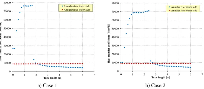
Fig. 13 – SGBT vs. RELAP5 v 3.3, reference simulations, convection HTC in the annular riser as function of tube length. ... 39
Fig. 14 – SGBT vs. RELAP5 v 3.3, reference simulations, temperatures at annular riser surfaces as function of tube length. ... 40
Fig. 15 – Flow regimes for vertical ducts for vertical ducts according to RELAP-5. ... 42
Fig. 16 – Heat transfer mode map at heat structures boundaries according to RELAP-5. ... 42
Fig. 17 – SGBT vs. RELAP5 v 3.3, reference simulation Case 1, flow regimes and heat transfer regimes at tube walls in the water-steam side. ... 43
Fig. 18 – SGBT vs. RELAP5 v 3.3, reference simulation Case 2, flow regimes and heat transfer regimes at tube walls in the water-steam side. ... 44
Fig. 19 – SGBT vs. RELAP5 v 3.3, improved input deck Case 1 vs. reference Case 1, thermal-hydraulic parameters of the hydrodynamic components as function of tube length. ... 48
Fig. 20 – SGBT vs. RELAP5 v 3.3, improved input deck Case 2 vs. reference Case 2, thermal-hydraulic parameters of the hydrodynamic components as function of tube length. ... 49
Fig. 21 – SGBT vs. RELAP5 v 3.3, improved input deck Case 1, heat structure parameters of the feedwater tube as function of tube length and comparison with the reference simulation. ... 51
Fig. 22 – SGBT vs. RELAP5 v 3.3, improved input deck Case 2, heat structure parameters of the feedwater tube as function of tube length and comparison with the reference simulation. ... 52
Fig. 23 – SGBT vs. RELAP5 v 3.3, improved input deck Case 1, heat structure parameters of the annular riser as function of tube length and comparison with the reference simulation. ... 53
Fig. 24 – SGBT vs. RELAP5 v 3.3, improved input deck Case 2, heat structure parameters of the
annular riser as function of tube length and comparison with the reference simulation. ... 54
Fig. 25 – SGBT vs. RELAP5 v 3.3, improved input deck Case 1, flow regimes and heat transfer regimes at tube walls in the water-steam side. ... 56
Fig. 26 – SGBT vs. RELAP5 v 3.3, improved input deck Case 2, flow regimes and heat transfer regimes at tube walls in the water-steam side. ... 57
Fig. 27 – HERO Facility Reference configuration, lead loop scheme with internal heating rods. ... 60
Fig. 28 – HERO Facility Reference configuration, heating rods and fissure. ... 61
Fig. 29 – HERO Facility Alternative configuration. ... 61
Fig. 30 – HERO Facility Reference configuration RELAP-5 input deck scheme. ... 63
Fig. 31 – HERO Facility, calculations in support to the determination of the radial geometry. ... 69
Fig. 32 – HERO Facility calculations in support to the determination of the computational time, mass flow rate. ... 71
Fig. 33 – HERO Facility calculations in support to the determination of the computational time, mass flow rate zoom. ... 71
Fig. 34 – HERO Facility calculations in support to the determination of the computational time, lead temperature in pipe 140. ... 72
Fig. 35 – HERO Facility calculations in support to the determination of the computational time, lead temperature in pipe 140. ... 72
Fig. 36 – HERO Facility, 4AX-2.5AY, mass flow rate as function of lead level at the fissures inlet. ... 73
Fig. 37 – HERO Facility, 6AX-2.5AY, mass flow rate as function of lead level at the fissures inlet. ... 74
Fig. 38 – HERO Facility, max-k, 4AX-2.5AY-0014A and 6AX-2.5AY-0010A versus SGBT, steam-water side. ... 76
Fig. 39 – HERO Facility, max-k, 4AX-2.5AY-0014A versus SGBT, lead side. ... 77
Fig. 40 – HERO Facility, max-k, 6AX-2.5AY-0010A versus SGBT, lead side. ... 77
Fig. 41 – HERO Facility, min-k, 4AX-2.5AY-0010A and 6AX-2.5AY-0007A versus SGBT, steam-water side. ... 78
Fig. 42 – HERO Facility, min-k, 4AX-2.5AY-0010A versus SGBT, lead side. ... 79
Fig. 43 – HERO Facility, min-k, 6AX-2.5AY-0007A versus SGBT, lead side. ... 79
Fig. 44– HERO Facility, FLUENT simulations, 2D geometrical domain. ... 80
Fig. 45 – HERO Facility, FLUENT simulations, temperature profile imposed at the wall separating the primary and the secondary circuit (from RELAP5 simulation). ... 81
Fig. 46 – HERO Facility, FLUENT simulations, detail of the mesh at the entrance of the cooling annular channel. ... 82
Fig. 47 – HERO Facility, FLUENT simulations, detail of the mesh at the exit of the cooling annular channel. ... 82
Fig. 48 – HERO Facility, FLUENT simulation C, mass flow rate at the inlet of the cooling channel. ... 83
Fig. 49 – HERO Facility, FLUENT simulation C, temperature at the inlet of the cooling channel. ... 83
Fig. 50 – HERO Facility, FLUENT calculations, heater schematization for the 3D analyses. ... 84
Fig. 52 – HERO Facility, FLUENT calculations, detail of the 3D geometry at the entrance of the
cooling annular channel. ... 85
Fig. 53 – Lead level regulation. ... 86
Fig. 54 – HERO Facility, FLUENT calculations, temperature profile imposed at the wall separating the primary and the secondary circuit ( RELAP5 simulation II). ... 86
Fig. 55 – HERO Facility, FLUENT calculations, details of the mesh at the entrance (a)and at the exit (b) of the cooling annular region. ... 87
Fig. 56 – HERO Facility, FLUENT calculations, details of the mesh: top view... 87
Fig. 57 – HERO Facility, FLUENT calculations, mass flow rate at the inlet of the cooling channel, (1/16). ... 88
Fig. 58 – HERO Facility, FLUENT calculations, average lead temperature at the inlet of the cooling channel ... 89
Fig. 59 – HERO Facility, FLUENT calculations, temperature difference between the inlet and the outlet of the cooling annular channel. ... 90
Fig. 60 – HERO Facility, FLUENT calculations, contours of temperature on the fissures and on three different z levels at the entrance of the cooling channel (simulation 4AX-2.5AY-005). ... 90
Fig. 61 – HERO Facility, FLUENT calculations, contours of temperature on three horizontal planes and on vertical planes trough the fissures symmetry planes at the entrance of the cooling channel (simulation 4AX-2.5AY-001). ... 91
Fig. 62 – HERO Facility, FLUENT calculations, mean velocity magnitude at the exit of the cooling annular channel. ... 92
Fig. 63 – HERO Facility, FLUENT calculations, contour of velocity at the exit of the cooling annular channel (simulation 4AX-2.5AY-005). ... 92
Fig. 64 – HERO Facility, FLUENT calculations, velocity magnitude vector at the exit of the cooling annular channel (simulation 4AX-2.5AY-005)... 93
Fig. 65 – PID scheme of the heating power system of HERO. ... 96
Fig. 66 – PID scheme of the pressurized cooling water system of HERO. ... 98
Fig. 67 – TxP conceptual scheme. ... 100
Fig. 68 – TxP design: PID. ... 101
Fig. 69 – TxP pre-assembling. ... 102
Fig. 70 – Thermal loads applied to test the candidate powders, scheme. ... 104
Fig. 71 – Scheme of the experimental facility. ... 104
Fig. 72 – Electrolytic copper powder LT-12 - 20°C. ... 105
Fig. 73 – Copper powder W-60-M - 20°C. ... 105
Fig. 74 – Brass powder OT-63 - 20°C. ... 105
Fig. 75 – AISI-316 powder - 20°C. ... 106
Fig. 76 – Sintetic diamond powder - 20°C. ... 106
Fig. 77 – Si-C powder - 20°C. ... 106
Fig. 78 – Al-N powder - 20°C ... 106
Fig. 80 – Copper powder W-60-M - 300°C. ... 108
Fig. 81 – Brass powder OT-63 - 500°C. ... 108
Fig. 82 – AISI-316 powder - 500°C. ... 108
Fig. 83 – Sintetic diamond powder - 500°C. ... 109
Fig. 84 – Si-C powder - 500°C. ... 109
List of tables
Tab. 1 - ALFRED SG main data (from the conceptual design). ... 22
Tab. 2 – Summary of the investigated insulating materials. ... 24
Tab. 3 – Preliminary screening, criterion 1: conductivity. ... 25
Tab. 4 – Summary of the results of the assessment of insulating materials. ... 26
Tab. 5 - ALFRED SG, hydrodynamic modeling of the feedwater tube. ... 29
Tab. 6 - ALFRED SG hydrodynamic modeling of the annular steam riser. ... 29
Tab. 7 - ALFRED SG, hydrodynamic modeling of the lead channel. ... 29
Tab. 8 - ALFRED SG, modeling of the heat structure between the feedwater tube and the annular riser. ... 30
Tab. 9 - ALFRED SG, modeling of the heat structure between the annular riser and the lead channel (active height only). ... 31
Tab. 10 - SGBT vs. RELAP5 v 3.3, reference simulations, assessment of hydrodynamic components. ... 35
Tab. 11 - SGBT vs. RELAP5 v 3.3, reference simulations, assessment of heat structures. ... 37
Tab. 12 – Summary of the sensitivity analyses. ... 46
Tab. 13 – HERO Facility, summary of the initial geometry. ... 62
Tab. 14 - HERO Facility, bayonet tube side, hydrodynamic modeling of the lead channel. ... 64
Tab. 15 – HERO Facility, hydrodynamic modeling of the lead channel down flow area. ... 64
Tab. 16 – HERO Facility, hydrodynamic modeling of the lead channel down flow area. ... 64
Tab. 17 – HERO Facility, hydrodynamic modeling of the lead channel down flow area. ... 65
Tab. 18 – HERO Facility, hydrodynamic modeling of the top holes. ... 65
Tab. 19 – HERO Facility, hydrodynamic modeling of the top holes. ... 65
Tab. 20 – HERO Facility, hydrodynamic modeling of the bottom holes. ... 65
Tab. 21 – HERO Facility, modeling of the heat structure between the feedwater tube and the annular riser. ... 66
Tab. 22 – HERO Facility, modeling of the heat structure between the annular riser and the lead channel (active height only). ... 67
Tab. 23 – HERO Facility, calculations in support to the determination of the radial geometry, summary of the results. ... 69
Tab. 24 – HERO Facility, definition of the potential radial geometries. ... 70
Tab. 25 – HERO Facility, assessment of the potential configurations, mass flow rates as function of fissures flow area (and lead level). ... 74
Tab. 26 – HERO Facility, max-k, comparison between selected configurations and SGBT... 76
Tab. 27 – HERO Facility, min-k, comparison between selected configurations and SGBT. ... 78
Tab. 28 – HERO Facility, summary of the simulations. ... 81
Tab. 30 – Test matrix of 3D simulations. ... 86
Tab. 31 – TxP main data. ... 100
Tab. 32 – TxP, schedule of the processing activities performed at the mechanical unit of Brasimone. ... 102
1
Introduction
The Generation IV International Forum (GIF), was chartered in July 2001 to promote the collaborative efforts of the world's leading nuclear technology nations to develop next generation nuclear technology. The main purpose of the initiative is to set-up innovative nuclear systems, candidate to reach technical and commercial maturity by 2040 [1] [2].
Initially, a large number of innovative Generation IV systems was considered. Liquid Metal cooled Fast Reactors (LMFR) are the most promising conceptual solutions. Among the Liquid Metal Coolants (LMC), sodium (Na) has by far the most important cumulated experience both in experimental and industrial nuclear applications. Nevertheless, due to the advantages of these kind of coolants, lead (Pb) or lead-bismuth eutectic (LBE) nuclear systems are proposed in the GIF together with sodium. Choosing LMCs for Fast Reactors (FR) is due to their high heat removal capabilities coupled with low interaction with neutrons.
The Lead cooled Fast Reactors (LFR) [3] [4] operates in the fast-neutron spectrum and use a closed fuel cycle for an efficient conversion of fertile uranium. The use of lead as primary coolant is motivated by several advantages, which can be summarized as follow [5] [6]:
• The promising nuclear properties, i.e. the low moderation rate.
• The non-existence of exothermic reactions between lead and water or air. This provides favorable conditions for the elimination of the intermediate circuit (typical of past Sodium cooled Fast Reactors).
• The high boiling point of lead (1749 °C at 1 bar). It allows to operate the reactor at low primary system pressure reducing the reactor vessel thickness. Furthermore, it eliminates the risk of core voiding due to coolant boiling.
• The high density of lead that favors fuel dispersion phenomena and prevents fuel compaction phenomena in case of core damage. This reduces the likelihood that fuel collects at the reactor vessel bottom in such a way that re-criticalities may occur.
• The high thermal capacity. It allows a significant grace time in case of loss-of-heat-sink accidents.
• The capability to retain FPs as iodine and cesium forming chemical compounds at temperatures up to 600 °C. This reduces the source term to the confinement/containment during accidents in which volatile fission products are released from the fuel matrix.
• The shielding capability against the γ-radiations.
Nevertheless, the molten lead has limitations. Lead is a an opaque heavy metal and its chemical properties imply corrosion and erosion problems with the structural materials. To partially mitigate them it is mandatory to work at relatively low temperatures compared to the other Generation IV reactors. Moreover, lead solidification may occur due to the high melting temperature (327 °C).
1.1
Framework and Objective of the Activity
The Lead-cooled European Advanced DEmonstration Reactor (LEADER) [7] project belongs to the
7th Framework Programme. It starts from the results achieved in the previous ELSY [8] (European Lead cooled System) project with the aim to improve its reactor configuration.
The main objective of LEADER [9] deals with the design of a 300 MWth low cost and fully representative scaled down European LFR Technology Demonstrator Reactor (ETDR) named ALFRED (Advanced Lead Fast Reactor European Demonstrator). An additional objective of the project focuses on the development of a new industrial size consistent reactor configuration based on ELSY: the 600 MWe European Lead-cooled Fast Reactor (ELFR).
In this framework, a new configuration of Steam Generator (SG) has been proposed: the super-heated steam double wall once through bayonet tube type. This conceptual design was studied since 60’ for Sodium Reactor application. An example of facility that operates with this concept is CIRCE (at ENEA Brasimone) even if it is limited to the heat exchange function.
The present activity aims to investigate the TH performance of the single bayonet tube. Its main objective is to test a single 1:1 bayonet tube (eventual improved in design) into an experimental facility representative of the TH in reactor behavior: the Heavy liquid mEtal – pRessurized water cOoled tube Facility (HERO Facility).
The activity starts in 2011 [10], the following sub-objectives were reached:
• Design of the TxP (Tubes for Powders) Facility devoted to powders conductivity measurement into an annular geometry representative of the bayonet tube. Its aim is to qualify powders for their application in the annular gap as heat transfer enhancer.
• Selection of candidate powders for the experimental campaigns based on bibliographic research.
• Preliminary assessment of the TH performance of the bayonet tube by means of RELAP-5. • Feasibility assessment on turbulence promoters for annular geometry subjected to two phase
flow.
During 2012, the following sub-objectives have been reached and documented in this report:
• Assessment of the SG single tube conceptual design with focus on the main design aspects that impact on its performance by means of TH system codes (RELAP-5).
• Definition of the main geometrical data of the heating power system of the Heavy liquid mEtal – pRessurized water cOoled tube Facility (HERO Facility) by means of TH system codes and CFD calculations.
• Setup of a preliminary PID of the heating power system and of the pressurized water loop of HERO.
• Experimental activities in support to the planning of the experimental campaigns in the TxP Facility and status of construction of TxP.
1.2
Structure of the report
This report is the result of a collaboration between UNIPI-UNIROMA1 and ENEA. It is subdivided in seven sections.
This first one points out the objectives and the framework of the activity. Section two describes the SG of ALFRED and points out the results of the screening of candidate insulating materials to be placed in the bayonet tube, between the descendent feedwater and the superheated steam riser.
In section three, the detailed assessment of the single tube performance by means of RELAP-5 is reported. Systematic comparison with the ANSALDO calculations are included. Sensitivity analysis are presented to highlight the influence of design, modeling issues and boundary conditions.
Section four focuses on the thermal hydraulic conceptual design of the heating power system of the Heavy liquid mEtal – pRessurized water cOoled tube facility (HERO). The section points out the potential geometries of a facility capable to test one 1:1 bayonet tube of ALFRED. RELAP-5 and FLUENT calculations are presented in this section. The calculations include the comparison between the performance of HERO and the bayonet tube as modeled in section three.
The preliminary PID of HERO is given in section five. Two preliminary schemes have been fixed: the heating power system (the lead circuit) and the pressurized water closed loop.
The status of advancement of the Tubes for Powders Facility (TxP) is discussed in the sixth section. The section includes the results of experimental tests (in furnace thermal loads) conducted at Brasimone.
2
ALFRED Steam Generator Bayonet Tube
2.1
Description
ALFRED reactor [7] includes eight once through double wall bayonet tube bundle type SGs [3] [9]. Preliminary calculations indicate that each SG has 510 tubes. A scheme of the ALFRED SG is shown in Fig. 1. Tab. 1 summarizes the SG and the bayonet tube main data.
The single unit is capable to remove 37.5 MW. It consists of the SG coupled with its axial pump located in the reactor hot side and integrated in the SGs (axial pump is the reference solution, jet pump is the alternative, Fig. 2). The pump suction is directly located above the reactor core, the lead flows into the pump and leaves its casing in appropriate fissures that connect the pump to the SG tube bundle. The lead crosses in down flow the bundle and leaves the SG at its bottom end. The SG active length is 6 m, the top head of the reactor pool is filled by Argon (1 m in height). The heat exchange between the water-steam bayonet tube and the lead is in counter-current.
The single bayonet tube consists of three concentric tubes, Fig. 3. It is made of T91. In each bayonet tube, the water flows downward in the inner tube (labeled as feedwater tube) and enters the annular space between the first and the second tube (labeled as annular riser) in up-flow where it starts to boil because of the heat exchange with the liquid lead that flows in counter-current [9].
The design requires the achievement of high temperature super-heated steam (450 °C, 180 bar). The molten lead is not in contact with the second tube. The third concentric tube (labeled as lead channel tube) separates it from the water-steam side providing a double barrier and the capability to monitor leakages from the tubes. This last safety function is achieved by means of pressurization of the annular gap with helium.
The study of this configuration is motivated by safety improvement. Indeed, it allows the double physical separation between lead and water sides. Furthermore, the leakage check system should prevent incident scenarios as lead-water-steam interaction due to steam generator tube rupture (SGTR).
On the other hands, the thermal efficiency of this configuration needs to be investigated and improved. In particular, two opened points should be carefully investigated [3]:
• The achievement of high temperature superheated steam requires the selection of an appropriate material to be placed within the gap between the annular riser and the lead channel tube (to increase the thermal conductivity of the gap).
• The heat exchange between the feedwater that crosses in down-flow the first tube and the superheated steam that rises up in the annular space should be minimized.
High conductivity powders and turbulence promoters were investigated in Refs. [10],[11] [12] [13]
Fig. 2 – LEADER Project, ALFRED pump casing and heat dispersion removal system.
Steam Generator general properties
Description Quantity Description Quantity
Removed Power [MW] 37.5 Number of tubes 510
Feed-water flow rate [kg/s] 24.1 Water pressure [bar] 180
Bundle geometry triangular Pitch / tube diameter 1.42
Feed-water temperature [°C] 335 Steam outlet temperature [°C] 450
Lead inlet temperature [°C] 480 Lead outlet temperature [°C] 400
Bayonet tube geometry
Description Quantity Description Quantity
Slave tube outer diameter [mm] 9.52 Slave tube thickness [mm] 1.07
Inner tube outer diameter [mm] 19.05 Inner tube thickness [mm] 1.88
Second tube outer diameter [mm] 25.40 Second tube thickness[mm] 1.88
Third tube outer diameter [mm] 31.37 Third tube thickness [mm] 2.11
Powder annular gap width [mm] 1.07 Length of heat exchange [mm] 6000
Argon plenum height [mm] 1000 He plenum height [mm] 800
Steam plenum height [mm] 800 T91 plates thickness [mm] 250
Feed-water flow rate [g/s] 47.3 Tube material T91
Tab. 1 - ALFRED SG main data (from the conceptual design).
2.2
Identification of Potential Insulators for the Inner Tube
The reference solution proposed by ANSALDO is the use of RLHY-12 insulating paint embedded into an annular region made of T91 (see Fig. 3).
Two design solutions are considered in this work. The first option deals with the sandwich shell proposed by ANSALDO in which the insulating material is bounded by two tubes: traditional fillers, alternative composite materials or thermal insulating paints are examined. The second option is characterized by a single central inner tube joined with an outer insulating ceramic coating. Ten criteria have been developed in order to assess candidate materials suitable to guarantee thermal insulation between the feedwater tube and the annular riser [14].
Criterion 1 Thermal conductivity:
In order to minimize the heat transfer between feedwater and superheated steam, the conductivity has been fixed by ANSALDO equal or lower than 0.05 W/mK. As preliminary approach, this limit is increased up to 0.5 W/mK.
Criterion 2 Operating Temperature range:
The operative conditions expected in ALFRED SG are 335 °C in the feedwater line and 450 °C in the steam line. The integrity of the insulating material does not affect the heat removal safety function. Therefore, the maximum temperature can be conservatively fixed to 600 °C.
Criterion 3 Compatibility with tubes material:
The chemical interaction (essentially corrosion) between thermal insulating material and surrounding tubes is not allowed.
Criterion 4 Compatibility with water and steam:
Potential fast chemical reactions with oxygen, water or steam at high temperature (335-450°C) should be considered. They must be avoided.
In the expected temperature operating conditions, transformations in thermo-physical properties of the candidate materials must be checked. In particular, it should be verified that temperature variations do not induce thermal conductivity increase, specific volume variations or formation of anisotropic strains within the material. Especially in ceramic coating, the worst consequence is separation and removal of insulating film from the tube wall. This may originate heterogeneity of the heat transfer.
Criterion 6 Thermo-mechanical effects in operating conditions:
An important matter is the preservation of the state of thermal insulating material during operation. Vibrations and tube differential thermal expansions due to thermal cycling can cause tubes sliding that induce localized strains within the thermal insulating material. The tube integrity should not be jeopardized by these effects.
Criterion 7 Resistance to radiation damage:
The effect of the radiation damage on thermo-physical properties (conductivity) of thermal insulating materials is quite unknown. Nevertheless, materials that experience strong nuclear reactions with neutrons should be avoided. It can be assumed that materials with high values of thermal neutron capture microscopic cross section (σa) that can originate activation are excluded. A
limit of σa is fixed to 10 barn (in the thermal energy spectrum). Gamma radiation damage should be
considered too.
Criterion 8 Ease of installation:
Materials must be characterized by easy techniques of installation and availability: deposition (for ceramic coating materials) or filling.
Criterion 9 Specific heat and mass density:
High specific heat and mass density lead to a low diffusivity coefficient. This last parameter is important in transient condition, when it is necessary to phase shift imposed thermal waves in time and to dampen them in intensity. Usually, insulating materials are characterized by low specific heat (below 2 kJ/kgK) and low density. No particular criterion is established as stringent requirement, in case of similar materials those with higher cp are preferred.
Criterion 10 Cost:
Cost is the last parameter considered in the selection.
The investigated materials are summarized in Tab. 2. They are grouped in four categories: A. Traditional fillers,
B. Alternative composite materials, C. Insulating paints and
D. Ceramic coatings.
Additional details are available in Ref. [14]. The preliminary screening was conducted based on criteria 1 and 2 in order to reduce the amount investigations. The complete assessment was then performed. The partial results (for criterion 1 only) and the final summary of the investigations are included, respectively, in Tab. 3 and Tab. 4. Only six materials survived the screening, they are considered potentially applicable to the ALFRED SG. Five materials refer to the sandwich shell design. Stone wool and Gemcowool® (two high temperature insulation wool produced by Refractory Specialties Incorporated) are traditional fillers. Pyrogel® (a silica aerogel insulation
blanket produced by Aspen Aerogels®) is an alternative composite material. Supertherm (developed by Enercheck Systems Inc. society) and RLHY-12 (produced by Beijing Ronglihengye Technology Company) are thermal insulating paints. The last material refers to tube outer coating. It is a Thermal Barrier Coating based on a recent and still under experimental investigation ceramic compound (BaLa2Ti3O10), characterized by a thermal conductivity that is close to the acceptability
limit.
CATEGORY SUB-CATEGORY MATERIALS
Traditional fillers
Mineral or rock wool Glass wool
Stone wool
High temperature
insulation wools
Alkaline-earth silicate glass wool Alumino-silicate glass wool Polycrystalline wool -- Fiberglass -- Cellular glass -- Vermiculite -- Perlite -- Calcium silicate
Flexible elastomeric foams Nitrile butadiene rubber
Ethylene propylene diene monomer
-- Polyethylene
Rigid foams Polyurethane
Polyisocyanurate Phenolic
-- Polystyrene
Alternative composite materials
Silica aerogel Spaceloft®
Pyrogel® Insulating paints -- NanoAyegh -- Atriathermika -- Thermo-Shield® -- Supertherm -- RLHY-12
Ceramic coatings -- BaLa2Ti3O10
Material Category Conductivity [W/mK] Criterion 1 limit [W/mK] Margin klimit/k Judgment Glass wool A 0.04 (35°C) 0.2 (650°C) 0.5 >2.50 Accepted Stone wool A 0.04 (35°C) 0.22 (650°C) 0.5 >2.27 Accepted Gemcowool® A 0.05 (200°C) 0.23 (980°C) 0.5 >2.17 Accepted Fiberglass A 0.03 (35°C) 0.075 (430°C) 0.5 >6.67 Accepted Cellular glass A 0.04 (35°C) 0.08 (205°C) 0.5 >6.25 Accepted Vermiculite A 0.065 (25°C) 0.14 (1090°C) 0.5 >3.57 Accepted Perlite A 0.065 (35°C) 0.135 (500°C) 0.5 >3.70 Accepted Calcium silicate A 0.055 (25°C) 0.123 (540°C) 0.5 >4.06 Accepted NBR A 0.24 (25°C) 0.5 <2.08 Accepted EPDM A 0.21 (25°C) 0.5 <2.38 Accepted Polyethylene A 0.042 (10°C) 0.5 <11.90 Accepted PUR A 0.025 (25°C) 0.5 <20.00 Accepted PIR A 0.027 (25°C) 0.37 (95°C) 0.5 >1.35 Accepted Phenolic A 0.021 (25°C) 0.5 <23.81 Accepted Polystyrene A 0.03 (25°C) 0.5 <16.67 Accepted Spaceloft® B 0.014 (50°C) 0.018 (150°C) 0.5 >27.78 Accepted Pyrogel® B 0.02 (0°C) 0.09 (600°C) 0.5 >5.56 Accepted NanoAyegh C - 0.5 - Unknown Atriathermika C 0.02 (25°C) 0.5 <25.00 Accepted ThermoShield® C 0.055 (25°C) 0.5 <9.09 Accepted Supertherm C 0.019 (25°C) 0.5 <26.32 Accepted RLHY-12 C 0.03 (25°C) 0.5 <16.67 Accepted BaLa2Ti3O10 D 0.6 (300°C) 0.5 (900°C) 0.5 >0.84 Accepted
Material Criterion
1 2 3 4 5 6 7 8 9 10
Glass wool A R N/A N/A N/A N/A N/A N/A N/A N/A
Stone wool A A A A A A U A A A
Gemcowool® A A A A A A U A A A
Fiberglass A R N/A N/A N/A N/A N/A N/A N/A N/A
Cellular glass A R N/A N/A N/A N/A N/A N/A N/A N/A
Vermiculite A A A A U R U N/A N/A N/A
Perlite A A A A R A U N/A N/A N/A
Calcium silicate A A A R A A U N/A N/A N/A
NBR A R N/A N/A N/A N/A N/A N/A N/A N/A
EPDM A R N/A N/A N/A N/A N/A N/A N/A N/A
Polyethylene A R N/A N/A N/A N/A N/A N/A N/A N/A
PUR A R N/A N/A N/A N/A N/A N/A N/A N/A
PIR A R N/A N/A N/A N/A N/A N/A N/A N/A
Phenolic A R N/A N/A N/A N/A N/A N/A N/A N/A
Polystyrene A R N/A N/A N/A N/A N/A N/A N/A N/A
Spaceloft® A R N/A N/A N/A N/A N/A N/A N/A N/A
Pyrogel® A A A A A A U A A A
NanoAyegh U R N/A N/A N/A N/A N/A N/A N/A N/A
Atriathermika A R N/A N/A N/A N/A N/A N/A N/A N/A
ThermoShield® A R N/A N/A N/A N/A N/A N/A N/A N/A
Supertherm A A A A U A U A A A
RLHY-12 A A A A A A U A A A
BaLa2Ti3O10 A A U U A A U A A A
A = Accepted R = Rejected U = Unknown N/A = Not Addressed
3
Assessment of the SG Bayonet Tube by Means of RELAP-5
The single bayonet tube has been modeled by means of RELAP version 5.3.3. RELAP5 is a light water reactor transient analysis code developed by the U.S. Nuclear Regulatory Commission (NRC) for use in rulemaking, licensing audit calculations, evaluation of operator guidelines and as a basis for a nuclear plant analyzer. It is a highly generic code that, in addition to calculating the behavior of a reactor coolant system during a transient, can be used for simulation of a wide variety of hydraulic and thermal transients in both nuclear and non-nuclear systems involving mixtures of steam, water, non-condensable and solute [16] [17]. In particular the version 5.3.3 has the capability to include the lead and LBE as coolant material.
Due to the bundle pitch to diameter ratio (1.45), the model is considered representative of the SG. In fact, as reported in the literature [18], for P/D > 1.35 the single unit can be considered un-coupled with the boundary units. A schematic overview of the nodalization adopted is reported in Fig. 4. The model includes: the feedwater tube, the annular steam riser and the equivalent lead channel. The analysis has been developed on the basis of the following assumptions:
• ••
• The heat exchange between the annular steam riser and the Argon zone has been neglected,
that means adiabatic behavior of the non-active region located outside the tube. •
••
• The conductivity of the insulating paint has been fixed, in agreement with ANSALDO
Nucleare recommendations [19], to 0.05 W/mK. •
••
• The filling powder is assumed as 0.3 porosity synthetic diamond based on the experimental
tests and the pretest calculations reported in Refs. [10] and [12]. Its conductivity has been selected on the basis of Ref. [10]. Therefore, two different equations are adopted to calculate this quantity, it is assumed that they provide a realistic boundary of the effective conductivity (see also section 3.2). They are labeled as Case 1 and Case 2.
• ••
• The heat transfer between the lead side and the annular riser is modeled according to the Mikityuk correlation that has been developed for fuel rod bundle [20].
Fig. 4 – ALFRED SG double wall bayonet tube, RELAP-5.3.3 model.
3.1
Development of the Reference Nodalization
The description of feedwater tube (pipe 100), annular steam riser (pipe 110) and equivalent lead channel (pipe 140) hydrodynamic components is reported from Tab. 5 to Tab. 7. The tables include the correlations adopted to calculate the quantities derived from the thermal hydraulic and geometrical data attached in Tab. 1. The hydraulic diameter of the equivalent lead channel is calculated assuming triangular array infinite bundle (that means hydraulic diameter equal to heated diameter).
The description of the heat structure between the feedwater tube and the annular riser (HS-1100) is given in Tab. 8. The main features of the heat structure between the annular riser and the equivalent lead channel (HS-1110) is summarized in Tab. 9.
COMPONENT LABEL TYPE DESCRIPTION
Pipe 100 Hydrodynamic component Feedwater tube
Id. Parameter Quantity Notes
a Axial node height 0.33500 m --
b N° axial nodes 10 --
c Axial node height 0.15000 --
d N° axial nodes 40 --
e Inner radius 0.00369 m --
f Flow area 4.27762*10-5 m2 f = π e2
g Operating pressure 180 bar --
h Inlet temperature 335 °C --
i Mass flow 0.047255 kg/s
j Hydraulic diameter 0.00738 m j = 2*e
Tab. 5 - ALFRED SG, hydrodynamic modeling of the feedwater tube.
COMPONENT LABEL TYPE DESCRIPTION
Pipe 110 Hydrodynamic component Steam riser
Id. Parameter Quantity Notes
a Axial node height 0.15000 m --
b N° axial nodes 40 --
c Axial node height 0.33500 m --
d N° axial nodes 10 --
e Annulus inner radius 0.00952 m --
f Annulus outer radius 0.01082 m --
g Flow area 8.27708*10-5 m2 g = (f2 - e2)*π
h Operating pressure 180 bar --
i Inlet temperature 335 °C --
j Mass flow 0.047255 kg/s --
k Hydraulic diameter 0.00259 m k = 4*g / [2 π*(f + e)]
Tab. 6 - ALFRED SG hydrodynamic modeling of the annular steam riser.
COMPONENT LABEL TYPE DESCRIPTION
Pipe 140 Hydrodynamic component Lead channel
Id. Parameter Quantity Notes
a Axial node height 0.15000 m --
b N° axial nodes 40 --
c Tube bundle pitch (triangular) 0.04500 m --
d Inner radius 0.01586 m --
e Equivalent flow area 9.629680*10-4 m2 e= {[(c2*2)*(cos(π /
6))] – [(π/*d2)/2]}*2
f Operating pressure 1.6 bar --
g Inlet temperature 335 °C --
h Mass flow 6.367647 kg/s --
i Hydraulic diameter (heated) 0.03864 m i = 4*e / 2 π*d
COMPONENT LABEL TYPE DESCRIPTION
1100 Heat structure Heat transfer between 100-110
Id. Parameter Quantity Notes
a Axial node height 0.33500 m --
b N° axial nodes 10 --
c Axial node height 0.15000 m --
d N° axial nodes 40 --
e Inner radius 0.00369 m --
f Radial interval width 2.14000*10-4 m T91
g N° radial intervals 5 T91
h Radial interval width 3.20556*10-4 m Insulator
i N° radial intervals 9 Insulator
j Radial interval width 3.76000*10-4 m T91
k N° radial intervals 5 T91
l Initial temperature 335 °C --
m Inner flow area 4.27762*10-5 m2 m= π c2
n Left boundary heated diameter 0.00738 m n = 4*m / 2 π*e
o Annulus inner radius 0.00952 m --
p Annulus outer radius 0.01082 m --
q Equivalent flow area 8.27708*10-5 m2 q = (p2 -o2)*π
r Right boundary heated diameter 0.00553 m r = 4*q / 2 π*o
Tab. 8 - ALFRED SG, modeling of the heat structure between the feedwater tube and the annular riser.
COMPONENT LABEL TYPE DESCRIPTION
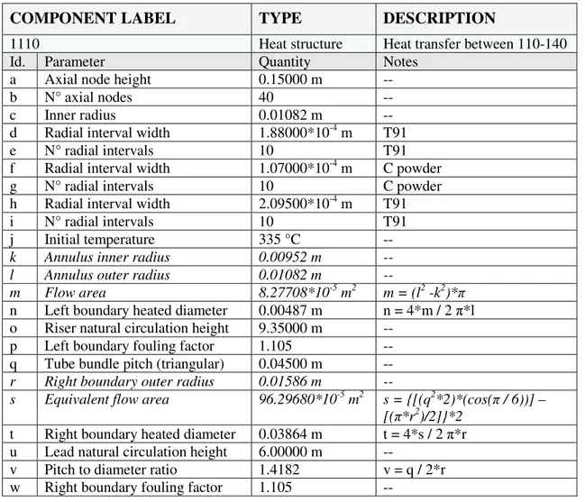
1110 Heat structure Heat transfer between 110-140
Id. Parameter Quantity Notes
a Axial node height 0.15000 m --
b N° axial nodes 40 --
c Inner radius 0.01082 m --
d Radial interval width 1.88000*10-4 m T91
e N° radial intervals 10 T91
f Radial interval width 1.07000*10-4 m C powder
g N° radial intervals 10 C powder
h Radial interval width 2.09500*10-4 m T91
i N° radial intervals 10 T91
j Initial temperature 335 °C --
k Annulus inner radius 0.00952 m --
l Annulus outer radius 0.01082 m --
m Flow area 8.27708*10-5 m2 m = (l2 -k2)*π
n Left boundary heated diameter 0.00487 m n = 4*m / 2 π*l
o Riser natural circulation height 9.35000 m --
p Left boundary fouling factor 1.105 --
q Tube bundle pitch (triangular) 0.04500 m --
r Right boundary outer radius 0.01586 m --
s Equivalent flow area 96.29680*10-5 m2 s = {[(q2*2)*(cos(π / 6))] –
[(π*r2)/2]}*2
t Right boundary heated diameter 0.03864 m t = 4*s / 2 π*r
u Lead natural circulation height 6.00000 m --
v Pitch to diameter ratio 1.4182 v = q / 2*r
w Right boundary fouling factor 1.105 --
Tab. 9 - ALFRED SG, modeling of the heat structure between the annular riser and the lead channel (active height only).
3.2
Assessment of the Reference Nodalization
Two distinct cases are analyzed in the reference simulations. They are labeled as case 1 and case 2. Both the calculations assume the annular gap filled by diamond powder at 0.3 porosity. The thermal conductivity of diamond is calculated based on the following correlations [10]:
Case 1
km = ks(1 - φ) * kfφ Eq. 1
Case 2
km/ kf = [λ] (0.208 - 0.757* log φ - 0.057* log λ) Eq. 2
where
k is the thermal conductivity [W/(m*K)],
s, f, m refers to solid, fluid and overall volume respectively, λ = (ks / kf)
The conductivity of diamond powder as function of porosity is depicted in Fig. 5. It should be pointed out that each correlation calculates the conductivity based on a simple function that depends upon three parameters:
1. The conductivity of the solid material (99.5% dense), 2. The conductivity of the fluid dispersed in the powder and 3. The porosity.
The weakness points of the correlations can be summarized as follow: 1. They are ideal correlations, and apply in specific range of porosity,
2. Each correlation investigated assumes spherical particles and does not account for the particle shape influence and
3. The influence of the particles diameter is not considered.
However, they are considered to embed (or at least provide a lower band) the real conductivity. Experimental campaigns are ongoing at ENEA CR Brasimone in the TxP Facility to assess the conductivity of different powders [12]. The analysis is subdivided in three main parts. The first one deals with the assessment of the hydrodynamic components. The second one focuses on the thermal structures, and the last one highlights the thermal-hydraulic behavior of the bayonet tube. Systematic comparison between the reference simulations and the results obtained by ANSALDO Nucleare is performed (when data are available).
0 40 80 120 160 200 240 0.2 0.3 0.4 0.5 0.6 0.7 0.8 0.9 1 C on du ct iv it y [W m -1K -1] Porosity [/] Case 1 Case 2
Fig. 5 – Thermal conductivity of diamond powder as function of porosity, calculated by Case 1 and Case 2 correlations, 200 °C.
3.2.1 Assessment of the Hydrodynamic Components
The results of the simulations are summarized in Tab. 10. The table contains the inlet and outlet temperature of each hydrodynamic component, the void fraction at tube outlet, the pressure drop in the bayonet unit and the lead velocity in the equivalent channel. The quantities refer to Case 1, Case
The details of the main thermal-hydraulic parameters are depicted in Fig. 6 a) and b). They deal with Case 1 and Case 2 respectively. Each figure reports:
• The feedwater tube temperature as function of the tube length, • The steam temperature in the annular riser as function of its length, • The primary coolant temperature (only the lead submerged length) and • The void fraction as function of annular riser axial elevation.
In agreement with ANSALDO, both the reference simulations predict a temperature increase in the feedwater tube in the range of 1.0 °C – 1.2 °C. The maximum steam temperature is predicted in the range 438-456 °C depending on the diamond conductivity (Case 2 and Case1 respectively). The ANSALDO simulation agrees with Case 1. In all the simulations the lead temperature drop is in the order of 80 °C. Void fraction close to 1 is reached within the first 3 meters of the annular riser (Case 1, Case 2 and ANSALDO) although different void fraction trends are highlighted in the three simulation before 3 m. In particular, ANSALDO calculations [19] highlight a void fraction plateau between 1.5 and 2 meters. This could be related to modeling issues (annulus component is used in ANSALDO model instead of pipe) and/or to the effect of an eventual spacer grid. Furthermore, the reference void fraction reaches the unit in a smoother way.
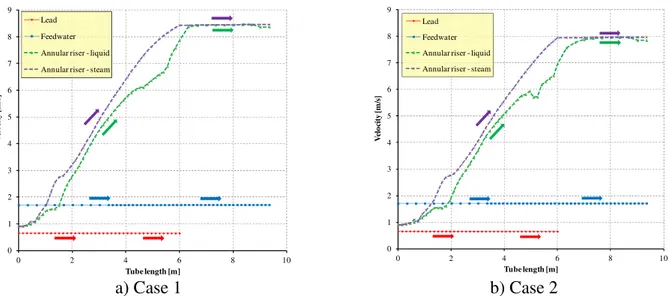
Pressure drops and velocities are represented in Fig. 7 and Fig. 8 (the indexes a) and b) refer to Case 1 and Case 2 respectively). The figures report:
• The feedwater pressure drop as function of the tube length, Fig. 7;
• The water-steam pressure drop in the annular riser as function of its length, Fig. 7; • The lead velocity (only in the immersed tube length), Fig. 8;
• The feedwater velocity as function of the tube length, Fig. 8;
• The water phase velocity in the annular riser as function of axial elevation, Fig. 8 and • The steam phase velocity in the annular riser as function of its length, Fig. 8.
The total pressure drop in the bayonet tube is predicted in the range of 2.6 bar – 2.8 bar. These values are close to the ANSALDO results even if they are lower. In the reference simulations, the lead and the feedwater velocities are characterized by approximately constant values along the tube length. These are equal to about 0.65 m/s in the lead channel and about 1.70 m/s in the feedwater side. The water and steam phase velocities increase within the lead submerged height (first 6 meters) because of boiling. Then, in the upper superheated steam zone, the super-heated steam velocity is predicted approximately constant in the range of 8 m/s – 8.5 m/s.
0 0.3 0.6 0.9 1.2 1.5 250 300 350 400 450 500 0 1 2 3 4 5 6 7 8 9 10 V o id f ra ct io n [ /] T em p er a tu re [ °C ] Tube length [m]
Annular riser Feedwater tube
Lead subchannel Annular riser void fraction
a) Case 1 0 0.3 0.6 0.9 1.2 1.5 250 300 350 400 450 500 0 1 2 3 4 5 6 7 8 9 10 V o id f ra ct io n [ /] T em p er a tu re [ °C ] Tube length [m]
Annular riser Feedwater tube
Lead subchannel Annular riser void fraction
b) Case 2
Fig. 6 – SGBT vs. RELAP5 v 3.3, reference simulations, void fraction, water and lead temperatures as function of tube length.
-1 -0.5 0 0.5 1 1.5 2 2.5 3 0 1 2 3 4 5 6 7 8 9 10 P re ss u re d ro p [ b a r] Tube length [m] Feedwater tube Annular riser -1 -0.5 0 0.5 1 1.5 2 2.5 3 0 1 2 3 4 5 6 7 8 9 10 P re ss u re d ro p [ b a r] Tube length [m] Feedwater tube Annular riser a) Case 1 b) Case 2
Fig. 7 – SGBT vs. RELAP5 v 3.3, reference simulations, pressure drops.
0 1 2 3 4 5 6 7 8 9 0 2 4 6 8 10 V el o ci ty [ m /s ] Tube length [m] Lead Feedwater Annular riser - liquid
Annular riser - steam
0 1 2 3 4 5 6 7 8 9 0 2 4 6 8 10 V el o ci ty [ m /s ] Tube length [m] Lead Feedwater Annular riser - liquid Annular riser - steam
a) Case 1 b) Case 2
Fig. 8 – SGBT vs. RELAP5 v 3.3, reference simulations, velocities. Parameter Unit Calc. Ref.
CASE 1
Calc. Ref. CASE2
Calc. ANSALDO
Lead inlet temperature °C 479.4 479.0 480.0
Lead outlet temperature °C 400.4 402.1 401.5
Feedwater inlet temperature °C 334.4 334.4 335.0
Feedwater tube temperature drop °C 1.2 1.0 <5.0
Immersed tube steam temperature °C 456.1 438.3 451.5
Superheated steam outlet temperature °C 453.9 436.1 450.1
Void fraction -- 1.0 1.0 1.0
Pressure drop bar 2.8 2.6 3.3
Lead velocity m/s 0.652 0.652 --
Lead velocity peak factor -- 1.004 1.004 --
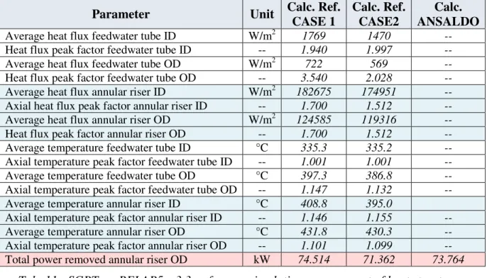
Tab. 10 - SGBT vs. RELAP5 v 3.3, reference simulations, assessment of hydrodynamic components. 3.2.2 Assessment of the Heat Structures
The assessment of the heat structures is summarized in Tab. 11. The table contains the average heat fluxes and surface temperatures in the feedwater tube and the annular riser surface boundaries. The
axial peak factor is also reported. Moreover, the table includes the total power exchanged by the annular riser outer surface with the lead side. The quantities reported in the table refer to Case 1,
Case 2 and ANSALDO Nucleare calculations (when available) [19].
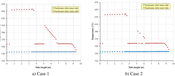
The thermal parameters of the feedwater tube are depicted from Fig. 9 to Fig. 11. Those of the annular riser are given from Fig. 12 to Fig. 14. The indexes a) and b) refer to Case 1 and Case 2 respectively. The figures include the following quantities:
• The heat flux that crosses the inner surface as function of the tube length, • The heat flux that crosses the outer surface as function of the length,
• The heat transfer coefficient (HTC) at the inner surface as function of the tube length, • The HTC at the outer surface as function of the length,
• The temperature at the inner surface as function of the tube length and • The temperature at the outer surface as function of the length.
In the reference simulations, the feedwater tube heat flux at the inner side shows three discontinuities, Fig. 9. The first one is at the steam outlet, the second one is about 4 meters far from the outlet, close to the end of the active region and, the last one, is located in the active region between 5-7 m. The outer side heat flux trend is similar to the inner side, it is scaled by the outer to inner surface ratio. The inner side HTC and surface temperature are approximately constant, this is due to the contact with sub-cooled water. The outer side HTC and surface temperature have a discontinuous behavior that reveals the occurrence of several heat transfer modes, Fig. 10 and Fig.
11. In order to explain these trends, further investigations are given in the next sub-section.
Both the reference simulations highlight a continuous increase of the heat flux at the outer and inner sides of the annular riser within the first 2.0 - 2.5 meters, Fig. 12. In fact, at the tube bottom, the water reaches saturated condition and begins to boil. This is reflected in the corresponding high HTC (Fig. 13). When superheated steam is reached, the HTC (and thus the heat flux at the inner side), decreases. At the outer side, the HTC is approximately constant, according to the Mikityuk correlation. The maximum temperature is close to 470 °C and it is reached at the end of the active length, Fig. 14. In agreement with ANSALDO calculations, the total power removed by the bayonet tube is in the range of 71.3 kW – 74.5 kW.
Parameter Unit Calc. Ref. CASE 1 Calc. Ref. CASE2 Calc. ANSALDO
Average heat flux feedwater tube ID W/m2 1769 1470 --
Heat flux peak factor feedwater tube ID -- 1.940 1.997 --
Average heat flux feedwater tube OD W/m2 722 569 --
Heat flux peak factor feedwater tube OD -- 3.540 2.028 --
Average heat flux annular riser ID W/m2 182675 174951 --
Axial heat flux peak factor annular riser ID -- 1.700 1.512 --
Average heat flux annular riser OD W/m2 124585 119316 --
Heat flux peak factor annular riser OD -- 1.700 1.512 --
Average temperature feedwater tube ID °C 335.3 335.2 --
Axial temperature peak factor feedwater tube ID -- 1.001 1.001 --
Average temperature feedwater tube OD °C 397.3 386.8 --
Axial temperature peak factor feedwater tube OD -- 1.147 1.132 --
Average temperature annular riser ID °C 408.8 395.0
Axial temperature peak factor annular riser ID -- 1.146 1.155 --
Average temperature annular riser OD °C 431.8 430.3 --
Axial temperature peak factor annular riser OD -- 1.101 1.099 --
Total power removed annular riser OD kW 74.514 71.362 73.764
Tab. 11 - SGBT vs. RELAP5 v 3.3, reference simulations, assessment of heat structures.
0 400 800 1200 1600 2000 2400 2800 3200 3600 0 1 2 3 4 5 6 7 8 9 10 H ea t fl u x [ W /m 2] Tube length [m]
Feedwater tube inner side Feedwater tube outer side
0 400 800 1200 1600 2000 2400 2800 3200 3600 0 1 2 3 4 5 6 7 8 9 10 H ea t fl u x [ W /m 2] Tube length [m]
Feedwater tube inner side Feedwater tube outer side
a) Case 1 b) Case 2
Fig. 9 – SGBT vs. RELAP5 v 3.3, reference simulations, heat flux in the feedwater tube as function of tube length.
0 10000 20000 30000 40000 50000 60000 0 2 4 6 8 10 H ea t tr a n sf er c o ef fi ci en t [W /m 2K ] Tube length [m] Feedwater tube inner side Feedwater tube outer side
0 10000 20000 30000 40000 50000 60000 0 2 4 6 8 10 H ea t tr a n sf er c o ef fi ci en t [W /m 2K ] Tube length [m] Feedwater tube inner side Feedwater tube outer side
a) Case 1 b) Case 2
Fig. 10 – SGBT vs. RELAP5 v 3.3, reference simulations, convection HTC at the feedwater tube surfaces as function of tube length.
310 330 350 370 390 410 430 450 470 0 1 2 3 4 5 6 7 8 9 10 T em p er a tu re [ °C ] Tube length [m]
Feedwater tube inner side Feedwater tube outer side
310 330 350 370 390 410 430 450 470 0 1 2 3 4 5 6 7 8 9 10 T em p er a tu re [ °C ] Tube length [m]
Feedwater tube inner side Feedwater tube outer side
a) Case 1 b) Case 2
Fig. 11 – SGBT vs. RELAP5 v 3.3, reference simulations, temperatures at the feedwater tube surfaces as function of tube length.