88
Chapter 5
5.1 Overview of in-vitro devices evolution
Dynamic culture conditions systems have several advantages, in comparison to static culture systems. Briefly they are summarized below:
Possibility to impose pressure gradient or shear stress in order to stimulate cells. Possibility to have an exchange of nutrients during the experiments as in the
physiological environment.
Higher oxygenation rate if compared to static cultures, due to the exchange of media.
Possibility to stimulate cross talk between different cell types.
In previous chapters I have shown how the simple bioreactor module ILT0 evolved into a complex system of 3 tissues for studying cellular cross talk of the In Live Tox system. Although the In Live Tox system is highly innovative and currently being used to provide important data on the effects of nanoparticles injection in the liver and in the endothelium, it did not prove easy for biologists to use. The reason for this is the In Live Tox system is different from biologist’s standard tool: the multiwell plate. Basically the plate is so common place that many analytical tools, such as those based on optical readouts are now designed around the multiwell plate (the so called plate readers). For this reason, we decided to design a plate compatible device for studying connected cultures and in-vitro models of cell-cell or organ cross-talk, in shape and dimensions similar to a multiwell plate, with slots where bioreactors can be housed. Moreover a system of channels is studied and integrated in the device as communication way between bioreactors. Dynamic conditions are assured by a peristaltic pump that applies a flow of culture medium to the device, as described for bioreactors in previous chapters. A multiwell where channels permit communications between slots is a project patented in 1983 by Holley [13]. In this
89 prototype dynamic conditions were assured by a sloping mutliwell plate. Liquid flowed from one slot to the next one through channels realized directly in the material. Over the past 20 years many systems have been studied, in order to solve fluid dynamic problems and permit the integration of new technologies and strategies to take measurements in real time, in order to monitor what happens to cells inside cell culture devices [14, 15]. A step forward is represented by the possibility to change topology of the fluid dynamic circuit. Devices where communication between slots is controlled by On / Off valves placed inside channels have been developed [16]. An On / Off valve permits the establishment of few circuit topology combinations. A strategy to change flow direction by a modification of connections has been studied here. The topology of the fluid dynamic circuit can be switched between a lot of alternatives and it is possible to set a new combination in real time during an experiment. Moreover pump, sensors and modules that monitor what happens inside the plate can be integrated in order to create a device that can be used stand alone. In the next paragraphs each parts that composes the device are described in detail.
5.2 Bioreactor support plate: a new patented device
The aim of this paragraph is to describe a device similar in shape and dimension to a Multiwell plate where slots can be used to house bioreactors. This system is called “bioreactor support plate” and has been patented [
12
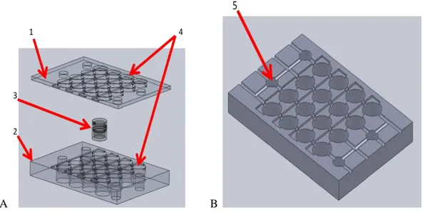
]. It is composed of a support that can be divided into two plates, an upper and a bottom one (figure 5.1, elements number 1 and 2), bioreactors (figure 5.1, element number 3) and control modules (figure 5.1, elements number 5). Each element requires a paragraph to be described clearly. The bioreactors are housed in cylindrical slots and substitute classical wells. Channels are realized between slots, in order and permit culture medium passage from a bioreactor to another one, avoiding leakage (figure 5.1 B). As discussed in paragraph 5.1 this characteristic represents a connection point between static culture paradigms and strategies to obtain dynamic conditions. In order to test the implemented solutions that will be described in next paragraphs a prototype was realized by Parker industries, using stereolithography (SLA). The material used to realize the prototype is Accura si 45HC, an optimized polymer for SLA applications90
A B
Figure 5.1 A: 3D view of Bioreactor plate composed of an upper level (1) and a bottom one (2). Bioreactors (3) can be housed in cylindrical slots (4). B: 3D view of Bottom plate
where slots to house control modules (5) are in evidence
5.2.1 Bioreactor plates
The system is composed of 2 transparent plates that mimic multiwell plates in dimensions and well positions: an upper one and a bottom one. Bioreactors and control modules are positioned in the bottom plate. When upper and bottom plates are joined, the support is closed. Both elements are characterized by slots channel pathways. Channel pathways are placed at the interface between the upper and bottom plates. This solution facilitates channel cleaning, controlling lumen permeability in order to prepare the system for a new experiment. In order to avoid gas bubbles attachment the same solution adopted for placement of tubes in the bioreactors described in chapter 3 is implemented. The longitudinal section of the outlet channels is placed on a higher plane than the inlet tubes. The aim is to drive air bubbles out from the chamber. This solution well fit the specifications of ILT0 bioreactors, which can be used in this device [10]. The connection between the outlet channel of a chamber and the inlet of the following unit requires particular design considerations. The stagger between the inlet plane and the outlet does not permit a simple connection. It is however necessary to minimize the hydraulic
91 resistance of the channels and avoid any local turbulence. Implemented solution is shown in figure 5.2: a pipe fitting whose longitudinal section is placed on an oblique plane, in order to fit the outlet of a module to the inlet of the following one.
A B
Figure 5.2 A: 3D view of a pipe fitting (1) which connects the outlet channel (2) to the inlet (3) of the following unit. B. Cross section view of a prototype where pipe fittings are
highlighted.
The solution avoids right angles in order to maintain laminar fluid conditions. Moreover the slope of the pipe fitting gives rise to a local increase in fluid velocity that represents a suitable solution in order to balance decelerations due to friction along fluidic circuit (figure 5.2). However the slope could give rise to gas bubbles, because of the change fluidic circuit shape. In order to solve this problem the outlet and inlet lumens have the same diameter, in contrast to the solution proposed in chapter 3. Moreover a vertical channel is connected to the upper section of each pipe fitting (figure 5.3). Air bubbles flow through the new part, because of their lower density compared to the liquid, so they remain entrapped in the vertical pipe. Figure 5.3 shows the solution and a fluid dynamic model implemented by COMSOL MULTIPHYSICS in order to simulate the fluid dynamic conditions inside the tilted pipe fitting.
92
A B
Figure 5.3 A: 3D view of a pipe fitting provided by a vertical channel in order to drive gas bubbles out of the fluidic circuit. B: picture of a model that simulate air bubble flow inside
the fluidic circuit.
Finally, in order to avoid leakage from the vertical channels, an on/off valve is placed at the top of the vertical pipe shown in figure 5.3. The valve permits liquid samples to be taken from the fluidic circuit as will be described in the following paragraphs.
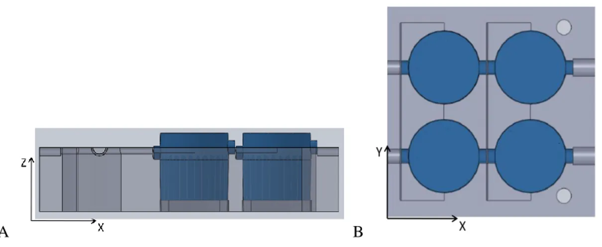
Channels permit the use of a peristaltic flow of medium to the bioreactors housed in slots. As described previously, slots are placed in correspondence to well positions of a commercial plate. This is a key point if the aim is to analyze bioreactor plate using a set up implemented for commercial multiwell plates. In general sensors of a classical plate reader move step by step basing on fixed distances in order to line up each well. Then it is important to maintain distances between well centres designing bioreactor slots. In order to avoid misalignments between slots and bioreactor a joints system is designed. Slots shape is moulded in order to create a conical junction with a cylindrical bioreactor. Conical joint avoids misalignment on the XZ plane (figure 5.4 A) Moreover inlet and outlet channels fit pipes connected to each chamber, in order to avoid any misalignment due to rotation of
93 bioreactor on the Z axis (figure 5.4 B). It is not possible to house bioreactor in a slot if its alignment is not correct.
A B
Figure 5.4 A: cross section view of slots where bioreactors (blue parts) are housed. Shape of the slot forces the module in a correct position on the XY plane. B: upper view of slots where bioreactors are housed. Inlets and outlets fit pipes of bioreactors, in order to avoid
any rotation on the Z axis.
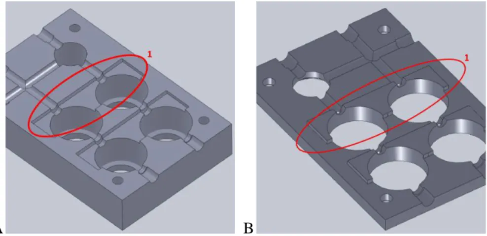
It is important to assure alignment between plates in order to close the system and allow reading of the bioreactor plate using a plate reader. A system of male-female joints between upper and bottom plates is studied (figure 5.5). These joints have a key role in system watertightness, because they assure the correct alignment between channels.
94
A B
Figure 5.5 A: 3D view of bottom plate. Female joint is highlighted by red circle (1). B:3D view of upper plate. Male joint is highlighted by red circle (1)
5.2.2 Bioreactor modules
A typical bioreactor module is represented in figure 5.6. It is a cylindrical shaped element characterized by a base diameter of 16 mm and 30 mm in height. It is composed of two sub units: an upper chamber and a bottom one. Modules derive from ILT bioreactors with some improvements. In contrast to ILT bioreactor modules in PDMS these modules should be in a transparent material like polypropylene. Furthermore it should also be rigid so that the modules do not deform as they are plugged into the slots on the plates. Actually the prototype was made of a material which was ideal for SLA but not transparent as shown in figure 5.6 B
95
A B
Figure 5.6 A:3D view of a bioreactor module. Blue part represents the bottom chamber. Each component should be realized in transparent and rigid material. B: bioreactor
module prototype realized in Accura si 45HC.
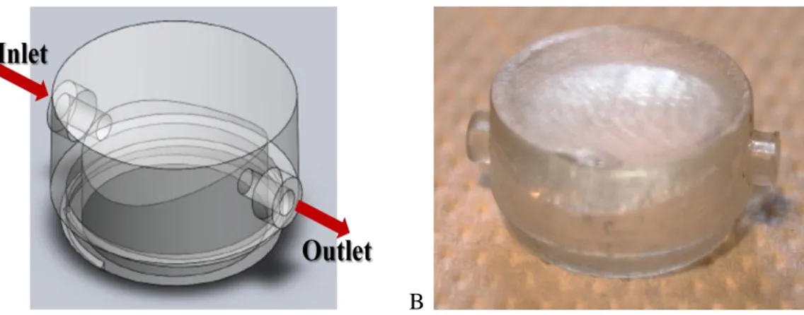
The upper chamber is similar to the ILT0 bioreactor. The aim of the new project is to realize something that is transparent and assures the possibility to look at inside the bioreactor using microscope. A rigid and transparent material represents the only solution that permits to meet the specifications. Using a rigid material such as polypropylene it is possible to design thinner bioreactor wall than ILT0, so reducing the dimensions of the whole object. On the other hand an interface between plastic parts cannot assure watertightness of the bioreactor. In order to solve this problem, the design of the upper chamber is modified to realize a male joint with a screw in order to screw the upper and bottom chamber. A rigid material permits the application of this strategy, in contrast to PDMS. The upper chamber screwed with the bottom one should assure the bioreactor watertightness. As described in chapter 3 a sloping roof represents a suitable solution to drive air bubbles outside from the chamber. Also in this rigid version the same technical solution is adopted as described for ILT bioreactors. Inlet and outlet are placed in the same position as in ILT bioreactors: the distance between planes of the longitudinal sections of inlet and outlet is 2 mm in height. Instead of using PDMS and flexible tubes to realize
96 inlets and outlets it is decided to implement rigid pipes. The length of each pipe is 2 mm and the diameter is 3 mm. These parts are important in order to create a joint with the support plates. The pipes fit inside channels pathway, forcing the correct alignment between chambers and plates. Figure 5.7 represents the upper chamber realized in rigid material. Inlet and outlet pipes are pointed out. In figure 5.7 B the prototype version is shown.
A B
Figure 5.7 A: Upper chamber is represented. Red arrows represent medium flow direction. B: upper chamber prototype
It has to be underlined that by using a rigid material to realize chambers it is possible to avoid any problems correlated to differences in pressure imposed by the clamp systems used in the ILT0. This consideration is important when a fluidic circuit characterized by parallel topology is implemented. In order to assure medium flow in both branches of the circuit bioreactors have to be subjected to the same pressure applied by clamps. It is not possible to control this parameter when chambers are realized in flexible material such as PDMS.
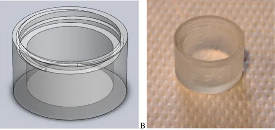
The bottom chamber has to house the male joint of the upper chamber and permit rotation of the parts while they are screwed together. The upper surface of the bottom chamber is moulded to obtain a thread that has to fit with the upper part. As described in ILT2 grooves on the bottom surface are not realized in order to avoid any problems of light scattering (figure 5.8).
97
A B
Figure 5.8. A: Bottom chamber 3D view. Screw thread is pointed out. B: bottom chamber prototype version
External surfaces shapes of the upper and bottom chambers are moulded in order to create a conical joint with slots of support plates.
5.2.3 Control modules
As claimed previously since 1983 evolutions of multiwell with channels pathway appeared. The innovation of bioreactors support plate is represented by the possibility to control the flow control modules. These elements can be housed in slots realized in plates as described for bioreactors. (figure 5.9).
98
A B
5.9 A: upper view of bioreactor plate. Slots where valves can be housed are pointed out be red circles (1). B: 3D view of 3 ways valve (1) that can be housed in slot
Control modules consist of three way valves, pumps and actuators that permit the modification of flow direction and velocity. In order to integrate a pump inside a control module an actuator system has to be designed based on dimension the plates. Miniaturize rotors and batteries to provide power in a humid environment represent an interesting task to be achieved in the future. Design and production of 3 way valves represents an easier step than pump project.
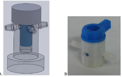
Valves units are joined in bioreactor plate by a male-female conical joints, in order to avoid any misalignments between channels and valves, as described for bioreactor modules. A hydraulic valve is composed of a core and a shield. Core part rotates inside the hollow shield, in order to control flow direction. The shield is a hollow cylindrical enriched by three protuberances that fit exactly with each channels in communication with slot. The joint system between shield and channels is the same described for bioreactors inlets / outlets and channels. 3 way valves can be a modified version of commercial unit in order to fit the bioreactor plate specifications (i.e. channels length) or fabricated by rapid prototyping (RP). In both cases each valve is made by a core and a shield structure. Figure
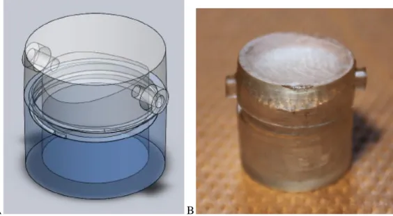
99 5.10 shows a design and an example of 3 way valves made by a core and a shield realized by 3D printer with a resolution of 120 μm .
A B
Figure 5.10 A: design of a 3 ways valve made by a core (blue part) and a shield (gray and transparent parts). B: example of a 3 way valve made by a core (blue part) and a shield
(white part)
5.3 System overview
Using 3 ways valves it is possible to control the direction of flow inside the plate, so with ILT bioreactors fluid circuit topology. It thus is possible to give a new meaning to the concept of modularity. In bioreactors ILT in fact modularity is associated with the possibility of connecting several modules in series or in parallel, following a LEGO like structure. In the new bioreactor plate 3 way valves allow to modify circuit topology, maintaining a fixed and rigid geometry. Modularity is now associated with the possibility of deciding which kind of circuit to use during experiments, starting from a fixed structure and reducing problems concerning the connection of subunits. In order to simulate physiological models it is important to have several degrees of freedom (DOFs) in the set up of the fluidic circuit. It could be required a circuit composed of modules joined in series to study cellular cross talk between tissues such as endothelial and hepatic tissues. Parallel
100 configurations could be a suitable solution to simulate drug uptake in different compartments of the same organ, such as sinusoids compartment and lymphatic ducts in the liver. Valves modules slots position is studied in order to permit several series and parallel configurations. It is also possible to use both circuits the topologies at the same time and in the same support plate. By switching flow direction it is possible to modify topology of the wet volume and so circuit configuration in real time during an experiment. Figure 5.11 shows an examples of configurations that can be switched by turning 3 ways valves.
A B
Figure 5.11 Examples of flow directions (red lines) that can be imposed in bioreactor plate. A: example of series configuration. 4 independent circuits, each composed by 4 bioreactors modules. B: example of parallel configuration (lines 2 and 3, each composed
by 4 bioreactors modules, joined in parallel) and a series configuration (line 1) obtained in the same device
As shown in figure 5.11 bioreactor support plate permits several circuit configurations at the same time, involving a gain in the number of experiments that can run with the same amount of material. Moreover it could be possible to increase the number of bioreactors used in the same experiment, choosing a variant of classical topologies as shown in figure 5.12. In this way all bioreactors slots are connected in series, maximizing the number of units and so increasing the surface area where cells can be seeded.
101 Figure 5.12 Example of variant of a series configuration. This topology could be useful
when a large number of bioreactors is required in an experiment
During an experiment it could be useful take samples of liquid for analysis cells. Ideally it should be possible take sampling directly from a chamber. In order to avoid problems concerning watertightness it was decided to realize sampling ports in correspondence with the outlets of each bioreactor. By this way it will be possible to study and analyze what happens in each module over time. As described previously a vertical channel crosses the upper plate in correspondence with the slopped channel. This connection way can be useful to take samples if desired. An on/off valve is positioned on the top of each vertical channel. When a sample is required, the valve is opened and medium can be withdrawn by a syringe. Then valve has to be closed in order to avoid any leakages. Sampling ports are implemented as shown in figure 5.13.
102
A B
Figure 5.13 A: upper view of bottom plate. Sampling ports displacement is pointed out by red lines(1, 2, 3). B: 3D view of bioreactor plate prototype. Sampling port are in evidence
(1, 2)
In the prototype realized to test the technical improvements the vertical cylindrical pipes are realized in correspondence with the position shown in figure 5.14. In this way it is easier to connect of pipes or on/off valves to the system.
103 Figure 5.14 Prototype 3D view. Vertical pipes in correspondence with sampling ports are
pointed out
PH and temperature sensors can also be added to the plate. Figure 5.15 shows the positioning of sensor units if desired.
Figure 5.15 Upper view of bottom plate. Connection ways to place sensors are pointed out by red lines