UNIVERSITÀ DEGLI STUDI DI CATANIA
Department of Industrial Engineering
Doctorate of Philosophy
Scienza e Tecnologia dei Materiali
XXVIII Ciclo
Salvatore Mannino
PhD Supervisor: Prof. Gianluca Cicala
PhD Coordinator: Prof. Maria Grazia Grimaldi
2015
ELECTROSPUN NANOFIBRES
FOR MULTIFUNCTIONAL
COMPOSITES
i
Dedication
The present work is dedicated to my two little nieces Giorgia and Giulia who, day by day, have been filling my life with so much joy
and
ii
Acknowledgements
I would like to thank my research supervisor Professor Gianluca Cicala for giving me the opportunity to work in this exciting area of research, supporting and guiding my work.
My appreciation is extended also to Professor Fabrizio Scarpa and the University of Bristol for the collaboration during the present work.
iii
Table of Contents
1. Polymer composites ... 1 1.1 Thermoplastics ... 7 1.2 Thermosets... 9 1.3 Polymer blends ... 11 1.4 Filled matrices ... 13 1.5 Chapter 1 References ... 182. Applications and drawbacks of epoxy/thermoplastic blends ... 19
2.1 Fundamentals of thermoplastic/epoxy blends ... 19
2.2 Matrices for composites... 27
2.3 Adhesive Bonding ... 40
2.4 Future applications ... 42
2.5 Chapter 2 References ... 46
3. Electrospinning: Process and Applications ... 47
3.1 History of electrospinning ... 48
3.2 The process ... 50
3.3 Spinning of Polymeric Nanofibres... 53
3.3.1Process parameters and fiber morphology ... 53
3.3.2Solution parameters and fiber morphology ... 55
3.3.3Properties of nanofibers ... 56
3.4 Application of electrospun nanofibres ... 58
3.4.1Filtration application ... 59
3.4.2Biomedical application ... 60
3.5 Chapter 3 References ... 67
4. Electrospun nanofibres reinforced composites ... 68
4.1 Why nanofibers as composite reinforcement? ... 68
4.2 Polymer composites reinforced with electrospun nanofibres: Literature review ... 72
4.2.1Electrospun nanofibers as bulk reinforcement of polymer matrix... 72
4.2.2Electrospun nanofibers as interface reinforcement of composite laminates ... 75
4.3 Chapter 4 References ... 78
5. Aim of the project ... 79
6. Experimental section ... 83 6.1 Materials ... 83 6.1.1 Epoxy resins ... 83 6.1.2Tougheners ... 84 6.1.3Crosslinkers ... 86 6.1.4Nanofillers ... 87 6.2 Samples preparation ... 89
iv
6.2.1Electrospinning of thermoplastic nanofibers ... 89
6.2.2Neat-resins preparation ... 91
6.2.3Composite laminates preparation ... 92
6.3 Characterization techniques ... 93
6.3.1Dynamic Mechanical Analysis ... 93
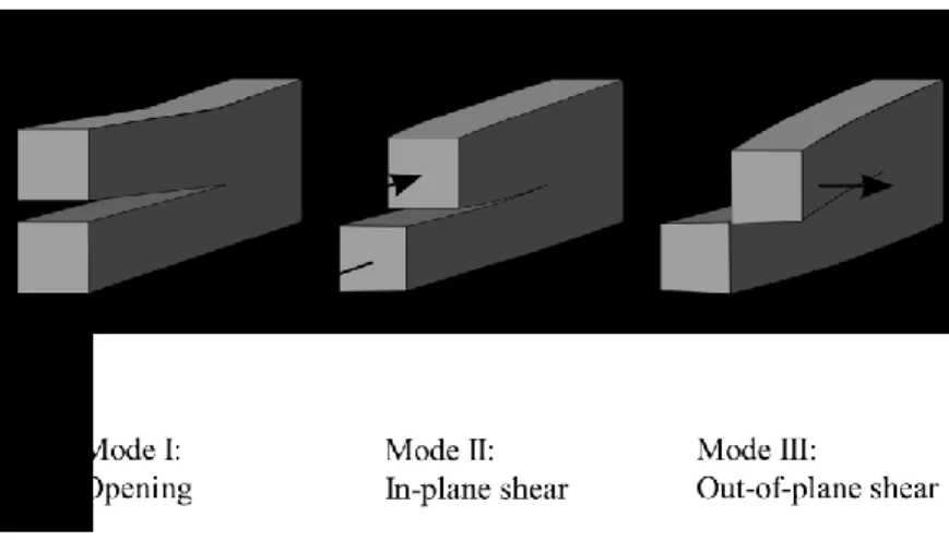
6.3.2Double Cantilever Beam Testing ... 98
6.3.3Scanning Electron Microscopy ... 105
6.3.4Hot-Stage Microscopy ... 107
6.3.5ANOVA and DoE Analysis ... 107
6.4 Results and discussions ... 110
6.4.1Electrostpun fibres characterization ... 110
6.4.2Neat resins characterization ... 124
6.4.3Composite laminates characterization... 135
1
1.Polymer composites
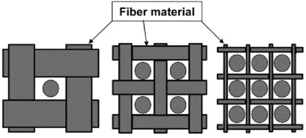
he term composite materials refers to a class of materials having three main constituents: matrix, reinforcement, and interface. The matrix in composite materials transfers load to the reinforcement and protects it from environmental degradation. Composites can be classified according to their matrix type. When metal or ceramic matrix materials are used, composites are referred to as metal matrix composites (MMCs) or ceramic matrix composites (CMCs), respectively. When polymeric matrix materials is used, composites are referred to as polymeric matrix composites (PMCs). Composite classification is also made according to the reinforcement used. Three reinforcement types are usually considered: long continuous fibers, short fibers and particles (figure 1:1).
Figure 1:1 Composites classified according to reinforcement types
T
2
Polymeric matrix composites are the focus of this chapter. PMCs present several advantages compared to traditional materials as shown in figure 1:2 through figure 1:5.
Figure 1:2 Modulus of elasticity
3
Figure 1:4 Density
4
Figure 1:6 reports the specific mechanical properties for different materials. This comparison highlights that composite materials outperform traditional materials when weight saving is the driving design factor.
5
Two types of polymeric matrixes are commonly used: thermoplastics and thermosets. Thermoplastics can be melted by heating and solidified by cooling, which render them capable of repeated reshaping and reforming. Thermoplastics can be either amorphous or semicrystalline. Thermoset materials, once polymerized, cannot be melted or formed again. The polymerization process is commonly called curing. While curing, resin molecules form three-dimensional networks in which they are connected by covalent bonds (cross-links). Owing to these cross-links, thermosets present good thermal stability and chemical resistance but cannot be reshaped after curing. Thermoplastic and thermoset composites are commercialized in different forms and are processed using a range of techniques. The choice of the manufacturing technique is driven by many factors including production volume, capital equipment cost, component shape and size, reinforcement form and tooling cost. Table
6 Table 1:1 Comparison of typical manufacturing techniques for polymeric composites
Hand Lay Up Filament Winding Pultrusion Spray Up Compression Moulding Roll Wrapping
Polymeric Matrix Thermoset Thermoset, Thermoplastic Thermoset, Thermoplastic Thermoset Thermoset, Thermoplastic
Thermoset, Thermoplastic Production
Speed
Low Slow to fast Fast Medium to fast Fast Medium to fast
Production Volumes Low to medium Low tomedium High Medium to high Medium to high Medium to High
Component Shape Simple to Complex Cylindrical and axisymmetric
Constant Cross Section Simple to complex Simple to complex
Fiber Volume Fraction
Low Medium to High Medium tohigh Low Medium to high Medium to high
Tool Cost Low Low Low Low High Medium
Capital Investement Cost
7
1.1 Thermoplastics
Thermoplastic resins are increasingly used as matrices for composites despite the fact that thermosets can be advantageous in terms of processability. Thermoplastics present some advantages over thermosets including:
High delamination resistance and damage tolerance
Low moisture absorption and excellent chemical resistance if semicrystalline thermoplastics are used
Low toxicity and infinite storage life due to absence of reactive chemicals Recyclability by re-melting of used matrices
Faster processing because no curing reaction is needed
The lack of tack of thermoplastics at room temperature is a key disadvantage over thermosets as it requires more sophisticated manufacturing processes for material deposition.
Over the last decade, interest in thermoplastic composites have increased as OEMs and part fabricators seek new ways to more efficiently produce structural components that have good damage tolerance and environmental performance.
Many thermoplastic types can be used as matrices. A common graph showing classification of thermoplastics consumption versus price and performance is shown in figure 1:7. Polyether-ether-ketones (PEEK), polyether-imides (PEI), polyphenyl-sulfides (PPS) and polysulfones belong to a special class of thermoplastics that can be used as matrices for niche applications. Commercial prepreg tapes such as carbon fibre/polyether-ether-ketone (CF/PEEK) and later carbon fibre/polyphenyl-sulfide (CF/PPS) were introduced in the early 1980s in the aerospace sector [1].
8
Figure 1:7 Price/performance profile for commercial thermoplastics
Traditionally, thermoplastics have not been suitable for processing at low pressures and in resin infusion processes such as RTM, VARTM or VAP. However, in the last decade novel thermoplastics with macro-ring structures, or cyclics, have been developed. These cyclic polymers can be processed at low pressures because their peculiar structure eliminates or reduces entanglements thus leading to very low viscosities. A typical structure for a cyclic-polybutylene-terephthalate (PBT) is shown in figure 1:8 where it is clearly shown that stannoxane molecules close the ring.
9
1.2 Thermosets
Thermosets are polymeric materials that form cross-linked networks after curing. These networks render the materials infusible and resistant to chemical agents. Thermosets have good heat retention and maintain their performance over time. They are less susceptible to ageing than thermoplastics. Thermosets present low viscosities in the unreacted state and thus they can be processed manually or at lower pressures compared to thermoplastics. The major limitation of thermosets is their inherent brittleness. Other shortcomings are their limited shelf life due to reactivity, the difficulty of reclaiming scrap material and, for some thermosets, the production of by-products during cross-linking reactions. Typical thermosets used as matrices
10 Table 1:2 Thermoset composites: properties and applications
Properties
Use Temp. [°C]
Cost Application Manufacturing Technique
Examples of Commercial Producers
Polyester
Simplest, room temperature curing, low mechanical properties, good chemical resistance (especially to acids)
60-150 Low
Piping, small boats, automotive, off-shore, civil industry
Hand lay-up, RTM, VARTM, filament winding, pultrusion, spray-up, compression molding
Dow, Ashland, Reichhold, Scott Bader, Cray Valley, DSM, Matrasur, Mapei
Vinyl ester
Better mechanical properties than polyesters, room to medium cure temperature, good chemical resistance (especially to acids)
60-150 Low
Piping, naval, automotive, off-shore, civil industry
Hand lay-up, RTM, VARTM, filament winding, pultrusion, spray-up, compression molding
Dow, Ashland, Reichhold, Scott Bader, Cray Valley.
Phenolic
Needs pressure over curing to avoid bubbling, medium mechanical properties, excellent fire resistance, excellent ablative properties
70-170 Low Interiors, ablatives, laminates Compression molding, RTM, filament winding Dow, J D Lincoln, Gurit, Seal.
Epoxy
Excellent mechanical properties, needs toughening for primary structures, dimensional stability, room to high cure temperature, good chemical resistance (especially to alkalis), very good adhesion to metals
80-215 Medium to high Piping, profile, automotive, naval, aerospace
Hand lay-up, pultrusion, filament winding, RTM, VARTM, autoclave, compression molding, out-of-autoclave
Gurit, Dow, Huntsman, Reichhold, Hexion, Cray Valley, Cytec, Hexcel, ACG, Toray, Seal, Sika, Mapei
Benzoxazine Excellent mechanical properties, medium to
high cure temperature, excellent fire resistance 80-250
Medium to high Interiors, aerospace components autoclave, RTM Henkel, Huntsman
11
Epoxies are available in liquid, solid and semi-solid forms. Liquid epoxies are used in RTM, filament winding, pultrusion, wet hand lay-up and other processes with various reinforcing fibres including glass, carbon, aramid and boron. Semi-solid epoxies are used in prepregs for vacuum bagging and autoclave processes. Epoxies are more costly than polyesters and vinyl esters and are therefore not used in cost-sensitive markets (e.g., automotive and marine) unless specific performance is needed. Increasing concerns about costs have encouraged the research of curing methodologies alternative to thermal curing both for epoxy and polyester resins. Microwave, electron beam and ultraviolet light (UV) curing being the most exploited.
1.3 Polymer blends
In most cases of industrial interest, polymer matrices present some deficiencies that limit their use. For example thermosets have good thermal stability, high environmental resistance and high modulus, but they are usually brittle. The poor toughness is largely due to their cross-linked structure and is an intrinsic limit for thermosets. To overcome this limitation many approaches are proposed in the literature (figure 1:9).
12
Figure 1:9 Toughening strategies for thermoset resins
The dominant approach has been to add a second phase which precipitates during cure and produces a multiphase morphology able to induce a variety of toughening mechanisms. Many different modifiers have been used: elastomers, polyurethanes, and ductile engineering thermoplastics among others. The use of elastomers typically causes a decrease in mechanical properties, particularly compression strength (due to the reduced resin modulus) and Tg.
Blending thermosets with thermoplastics is one of the most successful approaches because it does not have a significant effect on the balance of properties. Toughness enhancement is typically achieved by phase separation and is driven by many factors including the size and type of morphology, the polymer molecular weight, the backbone structure and end groups
13
and the ductility of the epoxy matrix. A co-continuous morphology is typically desired for the optimum balance of toughness and solvent sensitivity. A toughening technology used to obtain the highest damage tolerance is interlaminar or interleaf toughening. This exploits the concept of increasing the size of the interlaminar region in order to increase the size of the process zone and therefore the fracture toughness and compression after impact (CAI) of the composite. Methods to achieve interlaminar toughening include the additions of particles, films, fibres and veils.
Blending may improve resin or product performance by:
producing materials having a full set of the desired properties at lowest cost, improving product performance, and
improving processability.
1.4 Filled matrices
Filled matrices are matrices in which a sufficient quantity of a small size of a rigid material (filler) is well dispersed in order to improve certain key properties such as modulus, strength and viscosity or to reduce cost, shrinkage, etc. Conventional loading with traditional fillers typically ranges from 10 to 50wt%. The term filler is used for materials with characteristic dimensions in the range of 100-104 nm. This contrasts with nanofillers which range between 1 and 100nm. Fillers can be classified accordingly to their shape (figure 1:10), origin and size (figure 1:11).
14
Figure 1:10 Filler classification according to shape
Figure 1:11 Filler classification according to their size
As reported in Fig. 24 some fillers exhibit reinforcing capabilities and others do not [2]. The reinforcing activity of a filler depends on four factors:
15
Figure 1:12 Effect of filler's activity on properties of filled matrices
The specific area of the filler is calculated with the BET method. The BET method is widely used for the calculation of surface areas of solids by physical adsorption of gas molecules. Nitrogen is widely used for powdery fillers. An important factor that controls filled matrix mechanical properties is the interfacial adhesion between the filler and the matrix. The adsorption of polymer molecules on the filler surface results in the development of a layer which has properties different from those of the matrix polymer. The character, thickness and properties of this interlayer or interphase are relevant factors to control filled polymer properties.
The term nanofilled matrices refers to polymeric matrices compounded with fillers with characteristic dimensions in the nanometer range. Polymer nanocomposite is the most common name used to refer to such matrices. The fillers used for nanocomposites are usually referred to as nanofillers. Several types of nanofillers can be found that present one or more dimension in the nanometer range (figure )
16
Figure 1:13 Common nanofillers of interest for nanofilled matrices
Traditional filled matrices contain reinforcements with length in micrometers, and the interface of fillers is close to the bulk polymer matrix. In the case of nanocomposites, where the length of the reinforcement is on the nanometer scale, they have ultra-large interfacial area per volume, and the distances between the polymer and filler components are extremely short. Polymer coils are 40 nm in diameter, and the nanofillers are on the same order of magnitude; as a result, molecular interaction between the polymer and the nanofillers are thought to give nanofilled matrices unusual material properties that conventional matrices do not possess [3]. These unpredicted effects are also referred to as “nano-effects”. More recent results have, however, indicated that while the property profile is interesting, the nanoclay-based nanocomposites often obey continuum mechanics predictions and, in most cases, reinforcement effects obey composite theories where no “nano-effect” is considered [4]. Nanocomposites offer several advantages over the simple reinforcement effect that makes them of interest for composite materials. One big advantage is the possibility to realize matrices with sensing and actuation capabilities that can be used for the development of multifunctional composites [5]. Other non-structural functions achieved by nanocomposites include thermal and electrical conductivity, flame resistance and abrasion resistance. Thermal
17
and electrical conductivity are two of the most interesting functions that can be improved by the addition of nanofillers.
When developing nanofilled matrices key factors to achieve optimal reinforcing efficiency are: high dispersion degree to ensure the absence of nanofiller agglomerates in the micrometer range; good adhesion between matrix and nanofiller to ensure adequate stress transfer; and, in some cases (e.g., nanotubes and nanofibers), nanofiller orientation for optimal performance. The most complex and challenging task is to achieve fine and uniform dispersion because of the great interactions between nanofillers and the high matrix viscosity increase due to nanofiller addition.
18
1.5 Chapter 1 References
[1] L. A. Berglund in S.T. Peters, ed., Handbook of composites, Chapman & Hall, London, 1998, pp.115-130
[2] J.L. Leblanc, Filled Polymers: Science and Industrial Applications, CRC Press, Boca Raton, 2010.
[3] J.H. Koo Polymer Nanocomposites, McGraw Hill, 2006, DOI: 10.1036/0071458212 [4] D.R. Paul, L.M. Robeson, Polymer 49 (2008) 3187–3204
[5] C.Li, E.T. Thostenson, Tsu-Wei Chou, Composites Science and Technology 68 (2008) 1227–1249
19
2.Applications and drawbacks of
epoxy/thermoplastic blends*
poxy resins are the most used chemicals among thermoset materials [1]. This is due to their versatility which comes from their low viscosity as monomers and, at the same time, the good mechanical and thermal properties once curing reaction is completed. The main drawback of epoxies is the brittleness in the cured state. Other limitations are the shrinkage upon curing, the poor recyclability and, for some formulations, the low thermal resistance.
Most applications requires for improvements of the brittleness. In order to satisfy this requirement, epoxy resins can be toughened by adding a dispersed second phase material, which can be either a rubber or a thermoplastic. This dispersed material “slows down” the crack propagation leading to much higher energy to fracture values. The main areas of interest for toughened epoxy resins are matrix for composites, adhesive bonding and coatings and corrosion protection. The addition of thermoplastic leads to improvements in toughness that were exploited in several commercial systems. Blending thermoplastics with epoxy can also serve as a mean to develop smart functions like self-healing and shape memory effects.
In the present chapter the fundamentals of thermoplastic/epoxy blends will be recalled first and the main applications will be treated thereafter.
2.1 Fundamentals of thermoplastic/epoxy blends
A lot of research has been carried out for the development of polymeric systems to increase the fracture toughness of epoxides without decreasing their thermal and mechanical properties. Back in 1983 Bucknall and Partridge proposed the use of polyaromatics like polyether sulfones (PES) as modifiers for
E
20
epoxy resins as a solution to overcome the limitation of rubber toughening. The choice of this class of polymers is due to their high modulus and glass transition temperature, which are comparable to those of the epoxide resins. Tables 2:1 and 2:2 summarize some common amorphous and semi-crystalline
21 Table 2:1 Examples of amorphous thermoplastic polymers
Acronym Name Formula Tg (°C) Some commercial
Refernces
PES Polyether sulfone 220 Solvey
Virantage VW-10200, MnGPC: 46,500 Virntage VW-10300, MnGPC: 55,000 Virntage VW-10700, MnGPC: 21,000 Virntage VW-30500, MnGPC: 14,000
PEI Polyether imide 210 Sabic Ultem
1000, Mn=26,000 1040, Mn=9,900 PPE Poly(2,6
dimethyl-1,4-phenilene ether)
210 Sabic
820, Mn=12,000
PC Polycarbonate 140 Saic Lexan
PMMA Polymethylmetacrylate 110 Numerous
PS and SAN Polystyrene and Poly(styrene-co-acrylonitrile) and 11 Numerous
22
PVAc Polyvinylacetate 40 Union Carbide
LP40A, Mn=40,000 Phenoxy Poly(hydroxyl ether of
bisphenol A)
90 Union Carbide Mn=20,000
Table 2:2 Example of semicrystalline thermoplastic polymers
Acronym Name Formula Tg (°C) Tm (°C)
PE Polyethylene 110-140 PVDF Polyvinyliedene fluoride -50 170 PET PBT Polyethylene terephtalate Polybutylene terephtalate 60 60 270 220 PA6 PA11 PA12 Polyamide 40 43 42 216 185 177 i=2 i=4 i=5 i=10 i=11
23
When thermoplastic is added to epoxy, homogenous or not homogenous unreacted blends can be obtained. Upon curing three different scenarios can happen that result in different phase morphology. All the scenarios have been exploited in commercial systems as described in figure 2:1.
Figure 2:1 Toughening technologies of epoxy/thermoplastic blends
In the first case, if the thermoplastic is soluble in the resin, a homogeneous mixture is obtained. When curing starts, the mixture can either remain homogenous or phase-separate. This is the case for some commercial toughened epoxy prepreg systems like CYCOM® 977-series and HexPly® 8552. When phase-separation happens, it can lead to several types of morphologies, i.e. particulate, co-continuous and inverted. In the particulate morphology a thermoplastic-rich phase is dispersed in the epoxy-rich matrix; on the contrary, in the phase-inverted morphology an epoxy-rich phase is dispersed in the thermoplastic-rich phase. In the co-continuous morphology the two phases are segregated and interpenetrated altogether [2]. As described in figure 2:2 the initial thermoplastic concentration controls, among other parameters, the resulting morphology. Under particular circumstances, other special morphologies can be obtained (figure 2:3). bimodal Particulate morphology is one of the cases, in which the thermoplastic-rich particle present two average diameter values. Another case is he Secondary phase inversion, which
24
is the result of demixing of the epoxy phase inside the thermoplastic-rich domains occurring in post-curing conditions.
Figure 2:2 Effect of the thermoplastic concentration on the interlaminar morphologies of
thermoset/thermoplastic blends
Figure 2:3 Special interlaminar morphologies for epoxy/thermoplastic blends
When the initial mixture is homogeneous but no phase separation occurs during the cure of the resin, the final composite is a homogeneous transparent material. This can be due to the low concentration of the thermoplastic or due to the chemical affinity between the thermoplastic and the epoxy-hardener. Polycarbonate-epoxy and Polycaprolactone (PCL)/epoxy are an example of blend which do not phase separate upon curing.
If the thermoplastic polymer is not soluble in the epoxy resin, the initial mixture is not homogeneous and the thermoplastic particles remains dispersed in the epoxy before and after the cure. An example of these are polyamides (PA), polybutylene terephtalate (PBT) and
25
polyvinylidene fluoride (PVDF) (Yee 2000). Commercially speaking, this is the principle used by Toray Industries for toughening their Toray 3900 epoxy system.
In general, to achieve toughening effects the thermoplastic phase should act as an obstacle for crack propagation resulting in crack deviation or crack bridging. However, to a certain extent, homogenous blends can also be toughened by the presence of the thermoplastic chains within the epoxy network. The limitation of this approach can be that less energy is dissipated and that the thermal properties of the blend depends linearly on the relative amounts of the two components. This can be a limitation when the wrong thermoplastic is chosen. Thermoplastic-epoxy blends were developed to obtain materials with improved properties, like thermo-mechanical and solvent resistance. The thermoplastics reported in Table 2:1 have high glass transition temperatures, high modulus and good solvent resistance. The choice to use this type of thermoplastic was largely due to their superior properties compared to traditional reactive rubbers. The latter are performing much better in terms of toughening improvements but they also results in reduction of glass transition, modulus and solvent resistance for the epoxy blends. Other properties are influenced by the blending of thermoplastic with epoxy.
For example, thermoplastic polymers can be used as low-profile additives to improve the dimensional stability of thermoset resins. Often, they are used in polyester blends to have a better surface quality and to compensate the resin shrinkage. One of the most common polymer for this specific use is the polyvinyl acetate (PVAc). The mechanism works with a continuous thermoplastic rich phase that promotes cavitation in response to tensile stresses coming from internal deformation in the presence of mechanical constraints [3]. In epoxy prepregs, thermoplastics are used both as tougheners and as modifiers in order to keep a high elastic modulus of the composite during the cure of the thermoset at low temperatures, lower than the Tg of the thermoplastic polymer. This property of thermoplastic is particularly useful
26
to counteract the warpage in composite manufacturing due to resin shrinkage. Exact values of the amount of thermoplastic added is not released by companies as it is covered by trade secret. In most cases, it ranges from 15 to 30% by weight with respect to the resin matrix, depending on the specific application of the material.
Another application of epoxy-thermoplastic blends is the case of epoxy-phenolic coatings for magnetic disks. Porosity (macro or micro) is needed in the coating to enhance the retention of a lubricant used to increase the durability of the head-disk interface [4]. A well-known thermoplastic polymer used for this purpose is polyvinylmethyl ether (PVME) which, once is blended with the thermoset resins, phase-separates. Then, PVME is degraded by annealing at 220°C in oxidative atmosphere (air). The emission of volatile products leads to the formation of macro- or micro-porosity as shown in figure 2:4.
Figure 2:4 Steps to obtain a porous system from a PVME/Epoxy blend
Finally, in some cases, the epoxy is not the matrix of interest but thermoplastic/epoxy blending is used to enhance thermoplastic processing. Thermoplastic polymers can be
27
unprocessable. A common example is poly(2,6-dimenthyl-1,4-phenylene ether) (PPE), an amorphous thermoplastic with a glass transition temperature of 220°C. It softens at around 300-350°C, but at this temperatures it starts degrading as well. In order to overcome this issue, PPE is processed by blending with a small amount of an epoxy resin acting as a reactive solvent. Upon curing of the epoxy, when phase separation occurs, PPE matrix is obtained reinforced by a dispersed thermoset-rich phase [5].
In the following paragraphs the main applications down to earth are presented and some insight on future application under development or recent exploitation are also given. For commercial applications in relevant fields, like as matrices for composites, an extensive database of properties from producer is offered.
2.2 Matrices for composites
The business of epoxy/thermoplastic bends is well consolidated in the field of composite matrices for aerospace applications. Aircraft manufacturers are increasingly using composites because these materials offer great performances at a lower weight compared with metals, resulting in increased fuel efficiency, reduced maintenance and longer service life. Two examples of aircrafts with massive use of composites for primary structures are the Boeing 787 (figure 2:5) and the Airbus A380. The use of composites for primary structures requires tough systems therefore, thermoset/thermoplastic blends are the choice. The leading prepreg manufacturing companies (i.e. Cytec Engineered Materials, Hexcel and Toray Industries) are selling different systems based on thermoset/thermoplastic blends which are qualified for primary structures.
One of the largest supplier, in terms of volume, for the Boeing 787 is Toray Industries. The material used is Torayca 3900-series which is a highly toughened carbon fiber-reinforced
28
epoxy prepreg for the primary structures. The advantages of the use of composites are not limited to weight/economy benefits but extends to improved cabin pressure, bigger windows, less corrosion and extended maintenance schedules. The 787 incorporates also key components made with out-of-autoclave molding processes. Cytec Engineered Materials, now part of Solvay, offers a whole range of prepreg systems for out of clave curing ranging from the Cycom 5320 to the MTM series.
Figure 2:5 Boeing 787 “Dreamliner”
Hexcel has several new materials on the 787 as well. One is the HexMC. This product was selected for the 787’s larger window frames, which are considered a primary structure. For other window frames Hexcel proposed the use of the aerospace-qualified 177°C-cure 8552 epoxy prepreg resin. This system is also used for the engine nacelles made by GE and Rolls Royce. The 8552 epoxy resin is an example of toughened epoxy blend containing aromatic engineering thermoplastic.
The use of toughened thermoset/thermoplastic blends is not limited to aircraft structures. Several applications exist in the field of racing and exotic cars. The crashworthiness is the main benefit offered by these blends in these applications [6]. The use of high toughness prepregs results in better specific energy absorption as required by FIA (Federation Internationale de l'Automobile) rules. The study by Lo Faro et al was focused on the effect of
29
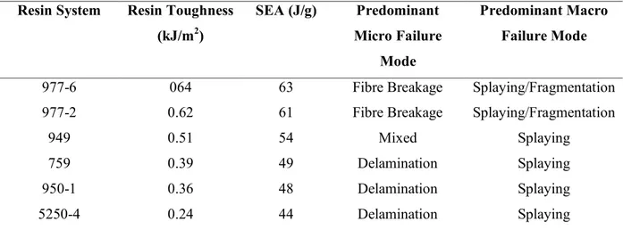
prepreg parameters like resin matrix and carbon fiber type on the crush behavior of composite tubes used as crush absorber in F1 cars. The data (table 2:3) shows a clear correlation between SEA and resin toughness values. Similar requirements are needed for structures like the nose cone (figure 2:6) and the rear crash structure (figure 2:7).
The use of impact resistant resin is transferred into exotic cars as demonstrated by several application like Ferrari LaFerrari, Lamborghini Aventador etc. For the Ferrari “LaFerrari”, Dr. Lo Faro, VP of Cytec, revealed the use of four different types of carbon fibre, all labour-intensively hand-laminated, before being cured in the autoclave [7].
Table 2:3 Impact resistance and failure modes of some CYCOM systems used in racing cars Resin System Resin Toughness
(kJ/m2) SEA (J/g) Predominant Micro Failure Mode Predominant Macro Failure Mode
977-6 064 63 Fibre Breakage Splaying/Fragmentation
977-2 0.62 61 Fibre Breakage Splaying/Fragmentation
949 0.51 54 Mixed Splaying
759 0.39 49 Delamination Splaying
950-1 0.36 48 Delamination Splaying
5250-4 0.24 44 Delamination Splaying
Figure 2:6 Impact test for a nose cone made by composite materials (from
30
Figure 2:7 Rear crash structure made in composites for F1 cars (from
http://leonardasf1.narod.ru/F1_Challenge/2011/2011_DEVELOPMENTS.html)
Cytec Engineered Materials, now part of Solvay, is one of the leading suppliers of composite materials for the aerospace applications. Its product portfolio (Table 2:4) includes prepregs and resin systems, adhesives and surfacing, carbon fibers, ancillary materials, tooling portfolio, process materials.
The CYCOM® 977 series, for example, include a number of epoxy prepregs toughened with aromatic thermoplastic. The formulation and structure of this thermoplastic is proprietary but the principle is based on the homogenous uncured blend turning into a phase separated cured blend. The toughening mechanism works with a co-continous morphology and shows excellent impact resistance. CYCOM® 977 prepregs are certified both for civil and military aircraft and used for several primary and secondary structures. CYCOM® 977-2 is a 177°C toughened epoxy resin (Table 2:5). Commercially speaking, it is the most important 977 system, being used for primary structures of commercial and military aircrafts and helicopters.
31 Table 2:4 Overview of commercial polymer matrixes for automotive and aircraft structures
Features and Applications Processing conditions Toughness Service temperature
dry [°C]
Out-Life at 25°C
CYCOM 2020 Modified epoxy-based prepreg system which displays excellent retention of mechanical performance at elevated temperatures
10 h at 80°C + optional 1 h at 150°C
post cure High - 8 wk
CYCOM 759 Modified epoxy prepreg. Provides superb surface finish with good hot/wet performance
14h at 70°C Medium 91 4 wk CYCOM 761 Modified epoxy prepreg. Designed for use as
thermal barriers (non load bearing) in motor sport applications
14h at 79°C or 45 min at 121°C Low 212 2 wk
CYCOM 919 Modified epoxy prepreg. 919 is widely recognized as the industry standard in race car construction. High toughness with mechanical performance and flame retardant. Self-adhesive with 4 wk tack life, suitable for sandwich panel construction. Also available in high flow version
1.5 h at 121°C Medium 143 4 wk
CYCOM 950-1 Modified epoxy prepreg. A 121°C curing system with the performance of a 177°C curing epoxy. A toughened system exhibiting excellent mechanical properties
2 h at 127°C Medium 177 4 wk
CYCOM 985 Modified epoxy prepreg. Suitable for the manufacture of carbon composite block for use in machining of solid carbon inserts
2 h at 127°C Low 193 10 d
CYCOM 977-2 Modified epoxy prepreg. Excellent hot/wet properties. Controlled flow, good surface characteristics
3h at 177°C High 200 10 d
CYCOM 977-6 Modified epoxy prepreg. Excellent hot/wet properties. Also used for primary aircraft structures
2 h at 154°C High 180 10 d
CYCOM 5215 Modified epoxy prepreg. Curable at 66°C with only vacuum bag pressure. The cured part will yield <1% void content. Mechanical property and service temperature range equivalent to first generation epoxy prepreg after post-cure at 177°C. Prototyping, repair, tooling and structural
application here controlled cost processing is desired.
32
Table 2:5 Typical Neat Resin Properties of the CYCOM 977-2 at Room Temperature Tensile Strength, ksi (MPa)
Tensile Modulus, msi (GPa)
11.8 ± 1.6 (81.4 ± 11) 0.51 ± 0.02 (3.52 ± 0.14) Flexural Strength, ksi (MPa)
Flexural Modulus, msi (GPa)
28.6 ± 1.0 (197 ± 7) 0.50 ± 0.01 (3.45 ± 0.07) G1C, in-lb/in2 (J/m2 ) 2.73 ± 0.48 (478 ± 84) K1C, ksi·in1/2 (MPa·m 1/2) 1.34 ± 0.15 (1.22 ± 0.14) Tg, C (RDS, 10C/minute) 212 Density, g/cc 1.31
Most commercial prepregs are formulated to be cured in autoclaves. The autoclave manufacturing has led in the past to very efficient composite and it is a well consolidated process. However, it has some main drawbacks. The first limitation is the high investment costs required for acquisition of the plant. Then the operation costs and the complexity of tooling have pushed the interest toward out-of-autoclave (OoA) manufacturing. OoA has been developed and suitable prepregs have been introduced leading to parts with autoclave-quality properties, by using vacuum bag-only (VBO) consolidation. In the VBO prepreg, the fabric is just partially impregnated in order to leave vacuum channels that let air escape during the consolidation in the vacuum bag. In this way, the amount of vacuums is reduced to very low values. Unlike the autoclave process, where the external applied pressure (≈ 7 atms) prevents the formation of volatile gasses leaving them dissolved in the resin, the VBO process works with only 1 atm. This means that all the volatile gasses must be taken out before the resin starts curing. The laminate composites produced from VBO prepregs have shown fiber volume content of about 65% for UD tapes and of about 55% for fabrics [8]. This is the main way to reduced operation costs since only conventional ovens and heating toolings are needed.
Among the resins for OoA Cytec's CYCOM® 5320-1 OoA prepreg is a toughened epoxy prepreg system. It can be processed by vacuum-bag-only but its performances are equivalent
33
to primary-structure-capable autoclaved prepregs (Table 2:6). The systems is characterized by a very low porosity. With a wet glass transition temperature of 163°C, an average water uptake of 0,55 wt% and because of its low temperature curing capability, it is also suitable for prototyping where low cost tooling or vacuum-bag-only curing is desired.
Table 2:6 Resin Characteristics of the CYCOM 5320-1
Shelf Life 1 year at < 10°F (- 12°C)
Tack Life 20 days at room temperature
Shop Life 30 days minimum at room temperature
Cured Resin Density, g/cc 1.31
Wet Glass Transition Temperature, °F (°C) 1 * 324 (163) Average Moisture Uptake, wt % 2 0.55
However, one main drawback of adding a toughening agent to epoxies is the very high increases of the resin’s viscosity. This makes most of the toughened commercial prepregs unsuitable for infusion techniques. To overcome such limitation, Cytec has developed the PRIFORM® technology. Manufacturing primary structure composite parts through liquid resin infusion requires the addition of the toughening agents to resin to assure performance standards are met. In Cytec's PRIFORM, the toughening agent is not blended with the resin but is woven into the textile preform. Figure 2:8 puts on evidence the scheme of the Priform fabric principle, showing the warp and the weft of the thermoplastic woven together among the carbon fibers. This solution allows resin infusion. The thermoplastic filaments are designed to be soluble in the resin at certain temperatures giving raise to homogenus dispersion in the epoxy first and, secondly, to phase separation. This unconventional approach leads to excellent structural performance coupled with infusion processability. The use of Priform in some airbus center fittings led to the international JEC awards for Cytec. The Priform technology has also some relevant side applications due to the self-binding aspect of
34
PRIFORM reinforcements. This means that the soluble fibers dispersed in the Priform fabrics can replace the use of binders helping to stabilize and process high quality preforms.
Figure 2:8 Scheme of the PRIFORM’s weaving
Cytec's PRISM® resin infusion systems represent a new step in to the resin infusion capability, delivering primary structure level performance without limitation in reinforcement or processing type. PRISM™ EP2400 is a single part, 180°C curing, toughened liquid epoxy resin system offering simple and flexible processing with the damage tolerance required for composite primary and secondary structure. PRISM EP2400 offers a dry Tg of 179°C and an exceptional wet Tg of 163°C following a two-hour cure at 180°C. It shows also very good mechanical properties, like a flexural strength of 164 MPa, flexural modulus of 3,6 GPa and a fracture toughness of 279 Jm-2. More characteristics of the neat resin are reported in table 2:7.
Table 2:7 PRISM EP2400 Neat Resin Characteristics
Property Specimen Conditioning Value
Cured resin density, g/cm3 (lb/ft3) Room Temperature, Dry 1.24 (77.4) Tensile strength, MPa (ksi) Room Temperature, Dry 95 (13.8) Tensile modulus GPa, (msi) Room Temperature, Dry 3.4 (0.49)
Tensile strain, % Room Temperature, Dry 7.2
Flexural strength, MPa (ksi) Room Temperature, Dry 164 (23.8) Flexural modulus, GPa (msi) Room Temperature, Dry 3.6 (0.52) Strain energy release, GIC, J m-2 Room Temperature, Dry 279 Fracture toughness, KIC, MPa m½ Room Temperature, Dry 0.96
CTE, x10-6 C -1 Room Temperature, Dry 60.5
Tg, °C (°F)* Room Temperature, Dry 179 (354)
35
As already said, aerospace is not the only application field for toughened epoxy. The serial automotive market needs light-weight, low-temperature, press-curable materials to meet legislative requirements for lower emissions, high safety and end-of-life recycling [9].
MTM®45‐1 is a flexible curing temperature, high performance toughened epoxy matrix system optimized for low pressure, vacuum bag processing. This system offers a combination of properties (table 2:8) that make it an ideal candidate for the OoA production. A whole range of the products available for OoA is presented in table 2:9.
Table 2:8 Physical properties of MTM45-1
Test Sample/test conditions Results Cured resin density 2 hours at 180°C 1.18 g/cm3
DMA E’ onset Tg, SACMA 2 hours at 180°C, dry 2 hours at 180°C, wet*
180°C 160°C Resin gel time At 80°C
At 130°C At 180°C
16.5 hours 90 minutes 10 minutes
*Wet ‐ 14 days immersion in water at 70°C
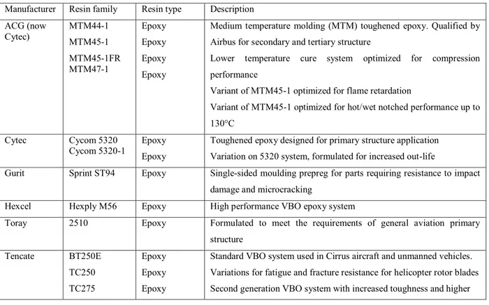
Table 2:9 Current-generation aerospace grade OoA/VBO prepreg resin systems
Manufacturer Resin family Resin type Description ACG (now Cytec) MTM44-1 MTM45-1 MTM45-1FR MTM47-1 Epoxy Epoxy Epoxy Epoxy
Medium temperature molding (MTM) toughened epoxy. Qualified by Airbus for secondary and tertiary structure
Lower temperature cure system optimized for compression performance
Variant of MTM45-1 optimized for flame retardation
Variant of MTM45-1 optimized for hot/wet notched performance up to 130°C
Cytec Cycom 5320 Cycom 5320-1
Epoxy Epoxy
Toughened epoxy designed for primary structure application Variation on 5320 system, formulated for increased out-life
Gurit Sprint ST94 Epoxy Single-sided moulding prepreg for parts requiring resistance to impact damage and microcracking
Hexcel Hexply M56 Epoxy High performance VBO epoxy system
Toray 2510 Epoxy Formulated to meet the requirements of general aviation primary structure Tencate BT250E TC250 TC275 Epoxy Epoxy Epoxy
Standard VBO system used in Cirrus aircraft and unmanned vehicles. Variations for fatigue and fracture resistance for helicopter rotor blades Second generation VBO system with increased toughness and higher
36 TC350-1 TC420 TC800 BMI Epoxy Cyanate ester Bismaleimide service temperatures
Third generation system with greater inspectability, resistance to hot/wet conditioning and curable at 135°C
Third generation system with increased out-life (45+ days), high toughness, and ability to cure at 135°C with 177°C required post cure High temperature system (service temperatures up to 315°C) High-temperature, toughened BMI prepreg formulated for cure out-of-autoclave
Henkel Loctite BZ Benzoxazine VBO prepreg based on a blended epoxy-benzoxazine resin formulation
The other big player for epoxy/thermoplastic for composites is the French company Hexcel. This company provides a wide range of prepregs for civil aircraft, military jets, helicopters, aero-engines or space satellite and launchers. Its range of resin formulations for aerospace prepregs includes a wide range of epoxies for highly loaded parts and toughness (table 2:10).
37 Table 2:10 Main commercially available Hexcel's toughened systems
Hexply Resin System
Attributes Typical Application Commercial
aircraft Interiors Helicopters Military jets Nacelles engines Space Uav’s
M26T Self adhesives, self
extinguishing Fairings / sandwich structures ✓ ✓
M76 High toughness, self adhesive, flexible cure
Space appliclations ✓ ✓
913 Versatile system with high
environmental resistance Structural components / fairings / helicopter blades
✓ ✓ ✓
M92 Self adhesive, self
extinguishing versatile system with high environmental resistance
Fairings / sandwich structures / structural components
✓ ✓
M20 High temperature performance
from low temperature cure Composite repair ✓ ✓
8551-7 Extreme damage resistance,
very high toughness Structural components / engine parts / fan blades
✓ ✓
M91 Latest product for aerospace structure and aeroengine, excellent toughness with very high residual compression strength after impact
Aircraft and aeroengine primary structure
✓ ✓
M21 Preferred product for aerospace structures, high toughness and excellent translation of IM fibre
primary structure ✓ ✓
8552 Preferred product for aerospace structures
Structural parts ✓ ✓ ✓ ✓ ✓
M56 High temperature performance from out of the autoclave cure, low density
Primary and secondary structures out of autoclave
✓ ✓ ✓
M18 Low moisture uptake, low
38
M18/1 Self extinguishing, very high
temperature wet performance Helicopter structural parts ✓ 922-1 High service temperature Engine / nacelle
structures ✓ ✓
HT93 Low FST Aircraft interior
panels / partitions ✓
200 Low FST, excellent ablative
properties Fire proof panels & components ✓ M65 High temperature, resistant
BMI system Parts subjected to very high temperatures
✓ ✓ ✓ ✓
F655 High temperature Primary / secondary structures, engine components toughnened
✓ ✓
996 Low water pick up Space and satellite
applications ✓
954-3 Low water pick up Space and satellite
applications ✓
954-6 Low water pick up Space and satellite
39
HexPly M91 is the very latest aerospace primary structure prepreg from Hexcel. With excellent toughness including very high residual compression after impact (see table 2:11), HexPly M91 can meet the growing needs of aerospace industry to manufacture lighter, faster and more efficient aircraft. This system is also suitable to be processed with both automated tape laying (ATL) and advanced fiber placement (AFP). These processing technologies are the choice to manufacture big composites parts like the three sectors of the 787 fuselage.
Table 2:11 Mechanical properties of Hexcel's M91
Mechanical properties Units Temp °C M91/34%/UD194/IM10-12K
Tg °C 185 - 190
Tensile strenght MPa 23 3520
Tensile modulus GPa 23 176
Compression strenght MPa 23 1880
Compression modulus GPa 23 156
ILSS MPa 23 105
CAI @ 30.5J MPa 23 350
Another widely commercialised system is the HexPly® 8552. HexPly® 8552 is a high performance tough epoxy matrix for use in primary aerospace structures. It exhibits good impact resistance and damage tolerance for a wide range of applications. It is an amine cured, toughened epoxy resin system supplied with unidirectional or woven carbon or glass fibers. The typical neat resin data are reported in table 2:12.
Table 2:12 Hexcel's 8552 neat resin properties
Colour Yellow
Density 1.301 g/cc
Glass Transition Temperature, Tg dry 200°C Glass Transistion Temperature, Tg wet 154°C
Tensile Strength 121 MPa
Tensile Modulus 4670 MPa
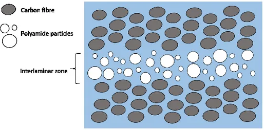
Toray Group is the Japanese company that developed one of the most used thermoplastic/epoxy blend based on preformed particles. The full commercial product,
40
T800H/3900-2, has heterogeneous interlayer including fine thermoplastic particles (figure 2:9), and it is used in the primary structures of Boeing 777.
Figure 2:9 Interlaminar toughening particles at interlayer region for T800H3900-2 laminates (schematic
drawing)
2.3 Adhesive Bonding
One drawback about composites is their cost of manufacturing and assembly. This is basically a problem for high volume production. In particular, the joining cost of composite components is one of the major cost drivers. One way to reduce cost of production is to apply specific joining technologies. Using epoxies as adhesive bonding is the main way to assemble composites components. Mechanical fastening, adhesive bonding and fusion bonding (welding) are the other developed joining technologies.
The disadvantages of epoxies as adhesive bonding are the need for surface preparation and, sometimes, long curing time. Composite welding is carried out by melting a thermoplastic polymer using it as adhesive. Usually a pre-treatment of surfaces is needed. By doing this, it is possible to achieve a very performant joint for composites, even better than adhesively bonded or mechanically fastened joints. Unfortunately, because of cross-linked nature, it is not possible to apply welding directly onto the thermoset surface of the composite. The use of a thermoplastic-thermoset blend as adhesive is a solution to indirectly overcome this issue,
41
otherwise it is also possible to use a thermoplastic film incorporated onto the cured thermoset surface. The thermoplastic and thermoset polymers partially blend before totally curing the thermoset resin. This leads to a thermoset surface with a thermoplastic attached on it. Therefore, it is possible to achieve fusion bonding of thermoset composites by means of various methods. The simultaneous application of heating and pressure, for example, causes the thermoplastic layers to soften, leading to a better contact between the adherent surfaces. Temperature also allows the thermoplastic chains to interdiffuse across the contact area. The welding of the surface layers is achieved with the disapperence of the interface due to the chains’ interdiffusion, thus obtaining a strong joint with less sensitivity to aggressive environments than adhesive bonded joints.
Cytec is among the world-leading suppliers of top quality adhesives specifically designed for bonding composites. Its products are qualified for use on aircrafts, having a portfolio ranging from high-performance adhesives to surfacing films and primers in a variety of product forms to enable manufacturing flexibility. Cytec’s aerospace adhesives and surfacing portfolio includes:
• Aerospace Adhesives
• Composite Surfacing
• Core Splice Foams and Potting Compounds
• Firewall Sealants
• Bonding Primers
HT® 424 is an aluminum-filled, modified epoxy-phenolic resin coated on a glass carrier which meets the federal and Military requirements. It was developed for bonding metal-to-metal and sandwich composite structures requiring long-term exposure to 149°C and short-term exposure to 260°C. HT 424 has adaptability to many bonding procedures. FM® 300 is a
42
modified epoxy film adhesive available with three different moisture-resistant polyester carriers. It is designed for bonding metal-to-metal and sandwich composite structures. Extensively used as a surface finished ply on composites material outside layers, FM® 300 film adhesive has unique properties that drastically reduce time-consuming sanding and filling operations. FM® 300 film adhesive has high elongation and toughness with high ultimate shear strength. This makes it particularly suitable for redistributing the high shear stress concentrations of graphite epoxy- to-metal bonds, and allows it to accommodate the low interlaminar shear strength of the composite. It is particularly good in fatigue resistance in these joints.
Hexcel formulates and manufactures a comprehensive range of structural film adhesives as well. The Redux® film adhesives range includes epoxy, phenolic and bismaleimide adhesives, supplied in film form or roll. Once cured, the adhesives form a permanent structural bond which is able to withstand harsh environments, including elevated temperatures. The range includes adhesives for metal-to-metal and composite bonding which find wide application in transportation, recreation and construction industries.
Redux® 319 is a high performance modified epoxy film adhesive curing at 175°C. It is available in both supported and unsupported versions at areal weights between 180 and 400 g/m2. The supported versions contain a woven nylon carrier for glueline thickness control and improved handle ability. Redux® 319 is a hot melt film which is free from solvents and consequently it has a very low volatile content.
2.4 Future applications
Self-healing materials are defined as those that have properties of repairing themselves after a damage has occurred, without losing their main functionalities. The growing interest in the
43
development of polymer nanocomposites with enhanced tribological performance is parallel to the increasing number of applications of polymers and polymer matrix composites. In fact, damage and failure are unavoidable in materials lives. Among thermoset materials, epoxy resins present a number of well-known advantages including toughness, high electrical resistance and thermal stability, and ease of fabrication. Epoxy resins are widely used in applications that range from electric and electronic systems to automotive parts, aircraft components, biocompatible implants, protective coatings, and adhesives. However, the tribological performance of epoxy resins are extremely poor due to their high brittleness and lack of self-lubricating behaviour, with severe wear due to crack propagation and fracture under sliding conditions.
Self-healing materials exhibit the ability to repair themselves and to recover functionality using the resources inherently available to them. Whether the repair process is autonomic or externally assisted (e.g., by heating), the recovery process is triggered by damage to the material. Self-healing materials offer a new route toward safer, longer-lasting products and components.
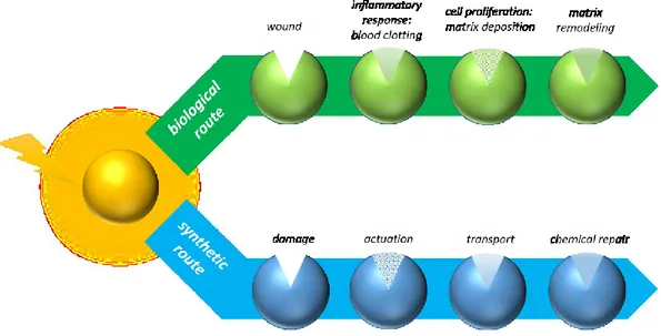
Brostow et al. [10] described the increase in scratch recovery of epoxy resin by the addition of a fluoropolymer. There exist numerous precedents [11, 12] of self-repairing or self-healing epoxy resin systems, usually by the addition of encapsulated curing agents which are released in the presence of fracture cracks, following the mechanism described in figure 2:10.
44
Figure 2:10 Autonomic healing (i.e. syntetich route) mimics the biological route of wound healing. Damages in
the matrix can break the microcapsules, releasing the healing agent into the crack plane through capillary action (transport). The healing agent bonds the crack repairing the material
Liu et al. [13] demonstrated that it is possible to achieve self-healing properties by introducing epoxy microcapsules containing a healing agent into an epoxy resin. The microcapsules were introduced by simply dispersion into the resin at ambient temperature. These microcapsules, made by interfacial polymerization of epoxy resin droplets with ethylenediamine, can be broken by the propagation of a crack. This is very useful for coatings, so that when surfaces are scratched, the microcapsules break and release the healing agent repairing the composite material. The experimental results showed that the artificial scratches were successfully healed in about 4-h after made. The self-healing coatings loaded with epoxy microcapsules undoubtedly have promise applications in the coatings and the self-healing films.
The Cornerstone Research Group (http://www.crgrp.com) developed a self-healing version of shape memory polymer (SMP) called Veriflex® EH (figure 2:11). This healable SMP resin will enable increased survivability for manned and unmanned air vehicles, spacecraft, habitats for space exploration missions, automobiles, and more.
45
Figure 2:11 Damaged (top) and self-healed Veriflex EH epoxy
Veriflex® EH is an epoxy-based resin that will be a direct replacement for current aerospace-grade epoxy resins. Veriflex® EH can be processed using vacuum-assisted resin transfer molding (VARTM), RTM, or wet lay-up techniques. CRG is also developing a prepreg formulation. Veriflex® EH uses two healing mechanisms to restore up to 85% of original mechanical performance. The first healing mechanism, shape recovery, brings the cracked or damaged area back into intimate physical contact. The second healing mechanism, polymer diffusion, allows long polymer chains to diffuse across the failure line and restore mechanical integrity. Both healing mechanisms are thermally activated and are achieved in less than three minutes. The system is claimed to reach 85% recovery of flexural strength.
*This chapter is under submission as contribution to the Handbook of Epoxy Blends, edited by Dr. Jyotishkumar Parameswaranpillai, Springer
46
2.5 Chapter 2 References
[1] Cicala G., Lo Faro C. (2012) Polymeric matrixes: materials type and modification strategies in Wiley Encyclopedia of Composites, John Wiley & Sons, New Jersey [2] Williams R.J.J., Rozenberg B.A. and Pascault J.P. (1997), Adv. Poly,. Sci., 128: 95 [3] Lucas J. C., Borrajo J. and Williams R .J. J. (1993) Polymer, 34: 1886
[4] Prime R.B. (1997), “Thermoset”, in Thermal Characterization of Polymeric Materials, E. A. Turi (ed.), 2nd Ed., Academic Press, San Diego
[5] Vendersbosch R. W., Meijer H. E. H (1997) “Processing of Polymers Using Reactive Solvents”, in Material Science and Technology, R. W. Cahn, P Haase and E. J. Kramer (eds.), Vol. 18, Processing of Polymers, H. E. H. Meijer (ed.), Wiley-VCH-Weinheim.
[6] Lo Faro C, Cicala G., Recca A., Sanders D. (2003) “Crash behaviour of composite materials : a DOE and fracture mechanics approach” Sampe International Confererence 2003, Paris
[7] http://www.topgear.com/uk/car-news/new-ferrari-laferrari-f150-revealed-geneva-2013-03-05
[8] Cytec Engineered Materials, unpublished data
[9] Centea T., Grunenfelder L.K., Nutt S.R. (2015) A review of out-of-autoclave prepregs – Material properties, process phenomena, and manufacturing considerations, Composites: Part A 70:132–154
[10] Brostow W., Bujard B., Cassidiy P.E., Hagg H.E., Montemartini P.E. (2002) Mater. Res. Mater. Res. Innov. 6: 7–12
[11] Yuan Y. C., Yin T., Rong M. Z., Zhang M. Q (2008) eXPRESS Polymer Letters Vol.2: 238-258
[12] Ratna D., Karger-Kocsis J. (2008) Journal of Materials Science, 43: 254–269. [13] Liu X.X., Zhang, H.R., Wang J.X., Wang Z., Wang S.C. (2012) Surf. Coat.
47
3.Electrospinning: Process and Applications
hen the diameters of polymer fiber materials are shrunk from micrometers to submicrons or nanometers, there appears several amazing characteristics such as very large surface area to volume ratio (this ratio for a nanofiber can be as large as 103 times of that of a microfiber), flexibility in surface functionalities, and superior mechanical performance (e.g. stiffness and tensile strength) compared with any other known form of the material. These outstanding properties make the polymer nanofibers to be optimal candidates for many important applications. A number of processing techniques such as drawing, template synthesis, phase separation, self-assembly, electrospinning, etc. have been used to prepare polymer nanofibers in recent years.
The drawing is a process similar to dry spinning in fiber industry, which can make one-by-one very long single nanofibers. However, only a viscoelastic material that can undergo strong deformations while being cohesive enough to support the stresses developed during pulling can be made into nanofibers through drawing. The template synthesis, as the name suggests, uses a nanoporous membrane as a template to make nanofibers of solid (a fibril) or hollow (a tubule) shape. The most important feature of this method may lie in that nanometer tubules and fibrils of various raw materials such as electronically conducting polymers, metals, semiconductors, and carbons can be fabricated. On the other hand, the method cannot make one-by-one continuous nanofibers. The phase separation consists of dissolution, gelation, extraction using a different solvent, freezing, and drying resulting in a nanoscale porous foam. The process takes relatively long period of time to transfer the solid polymer into the nano-porous foam.
48
The self-assembly is a process in which individual, pre-existing components organize themselves into desired patterns and functions. However, similarly to the phase separation the self-assembly is time-consuming in processing continuous polymer nanofibers.
The electrospinning process seems to be the only method which can be further developed for mass production of one-by-one continuous nanofibers from various polymers. Electrospinning has emerged as a powerful technique for producing high strength fibers due to its versatility, ease of use, ability to align structures and control fiber diameters. Some of these unique features cannot be otherwise achieved by conventional fiber processing techniques mentioned above. Another merit is that under the influence of an electric field, electrospinning self-assembles dispersed fillers along the axial direction such that composites can be formed by imposing additional spatial confinement to the polymer chains. These reinforced fibers display superior properties and function as basic building blocks for the fabrication of high strength structures using a bottom-up approach. For example, carbon nanotubes (CNTs) and carbon black (CB) particles are among the commonly used fillers which are dispersed within the fibers to mimic the functionality of silk fibers for high strength and toughness applications.
3.1 History of electrospinning
The origin of electrospinning as a viable fiber spinning technique can be traced back to the early 1930s. In 1934, Formhals patented his first invention relating to the process and the apparatus for producing artificial filaments using electric charges [1]. Though the method of producing artificial threads using an electric field had been experimented for a long time, it had not gained importance until Formhals’s invention due to some technical difficulties in earlier spinning methods, such as fiber drying and collection. Formhals’s spinning process
49
consists of a movable thread collecting device to collect the threads in a stretched condition, like that of a spinning drum in the conventional spinning. Formhals’s process was capable of producing threads aligned parallel on to the receiving device in such a way that it can be unwound continuously. The first spinning method adopted by Formhals had some technical disadvantages. It was difficult to completely dry the fibers after spinning due to the short distance between the spinning and collection zones, which resulted in a less aggregated web structure. Formhals refined his earlier approach to overcome the aforementioned drawbacks.
Subsequently in 1940, Formhals patented another method [2] for producing composite fiber webs from multiple polymer and fiber substrates by electrostatically spinning polymer fibers on a moving base substrate. In the 1960s, fundamental studies on the jet forming process were initiated by Taylor [3]. In 1969, Taylor studied the shape of the polymer droplet produced at the tip of the needle when an electric field is applied and showed that it is a cone and the jets are ejected from the vertices of the cone. This conical shape of the jet was later referred to by other researchers as the “Taylor Cone” in subsequent literature. By a detailed examination of different viscous fluids, Taylor determined that an angle of 49.3 degrees is required to balance the surface tension of the polymer with the electrostatic forces. The conical shape of the jet is important because it defines the onset of the extensional velocity gradients in the fiber forming process. In subsequent years, focus shifted to studying the structural morphology of nanofibers. Researchers were occupied with the structural characterization of fibers and the understanding of the relationships between the structural features and process parameters. Wide-angle X-ray diffraction (WAXD), scanning electron microscopy (SEM), transmission electron microscopy (TEM), and differential scanning calorimetry (DSC) have been used by researchers to characterize electrospun nanofibers.
In 1987, Hayati et al. [4] studied the effects of electric field, experimental conditions, and the factors affecting the fiber stability and atomization. They concluded that liquid conductivity