and Materials
Engineering
Modern and Historical Engineering Components
Investigated by Neutron Diffraction
on ENGIN-X*
Anna M. PARADOWSKA
*1,*2, Anton TREMSIN
*3, Joe F. KELLEHER
*1,
Shu Yen ZHANG
*1, Sanjooram PADDEA
*4, Genoveva BURCA
*4, Jon A. JAMES
*4,
Rehan AHMED
*5, Nadimul H. FAISAL
*6, Francesco GRAZZI
*7, Giulia FESTA
*8,
Carla ANDREANI
*8, Francesco CIVITA
*9, Peter J. BOUCHARD
*4,
Winfried KOCKELMAN
*1and Michael E. FITZPATRICK
*4 *1 ISIS, Rutherford Appleton Laboratory, Didcot, OX11 0QX, Oxfordshire, UKE-mail: [email protected]
*2 Australian Nuclear Science and Technology Organisation, Lucas Heights, NSW 2232, Australia
*3 Space Sciences Laboratory, University of California at Berkeley, Berkeley, CA 94720, USA
*4 Materials Engineering, The Open University, Milton Keynes, MK7 6AA, UK
*5 School of EPS, Heriot-Watt University, Edinburgh, EH14 4AS, UK
*6 College of Engineering, Alfaisal University, Riyadh 11533, KSA
*7 Consiglio Nazionale delle Ricerche – Istituto Sistemi Complessi, Sesto Fiorentino (FI), Italy
*8 Università degli Studi di Roma Tor Vergata, Rome, Italy
*9 Museo Stibbert, Via Stibbert 26, Firenze, Italy
Abstract
The ENGIN-X beamline is mainly used to determine residual strains/stresses deep within the interior of bulk engineering components. It is mainly used by scientists and engineers for the development of modern engineering processes and structural integrity investigations. ENGIN-X diffraction and transmission mode can be a very useful tool to measure strain, phase transitions, texture and material composition in spatial resolution in historical or archaeological artifacts and modern materials. The complexity of the shapes and sizes of the samples measured on ENGIN-X varies significantly between experiments, and this required the development of better planning, simulation and control software, SScanSS. In this paper an overview of recent developments in strain scanning on ENGIN-X and a highlight of current scientific research are presented.
Key words: Neutron Diffraction, Heat Treatment, Residual Strain and Stress,
Welding
1. Introduction
Residual stresses can have important consequences on the performance of engineering components [1]. There are several ways of measuring residual stresses in small volumes. The most common ones involve mechanical invasive methods (e.g., hole drilling or cutting [2,3]) and non-destructive methods using radiation such as x-ray (laboratory or synchrotron) or neutron diffraction [4-8]. Neutron diffraction is outstanding in the ability to obtain residual stresses non-destructively within the subsurface and deep within the bulk of *Received 1 Dec., 2011 (No. R-11-0748)
[DOI: 10.1299/jmmp.6.408]
Copyright © 2012 by JSME
the components. Neutrons can evaluate the weld structure in three directions, with spatial resolution of 1 mm (or less) to a depth of many millimetres below the weld surface (up to 50 mm for steel). An international standard ISO/TS 21432-2005 [9] for measuring residual strain/stress using neutron diffraction is being developed on a ring-plug fit to achieve reproducible and reliable stress measurements. For diffraction techniques, the estimate of the absolute value of the strain being measured relies on the use of a zero-stress, reference sample. Thus there is a requirement for the preparation of a zero-stress reference sample from a “look alike” sample or destructively from the sample itself after the measurements.
The ENGIN-X [7,10] is the dedicated materials engineering neutron beamline at ISIS. The primary function of the beamline is the determination of residual strain, and thus stress, deep within crystalline materials using the atomic lattice planes as an atomic 'strain gauge'. Internal stresses in materials have a considerable effect on material properties including fatigue resistance, fracture toughness and strength. A second important function of the beamline is studying of fundamental material behaviour, such as composite and rock mechanics, the basic deformation mechanisms [11-13] of metals, and phase transformations in shape memory alloys and ferroelectrics.
Complimentary to diffraction technique is transmission mode also available on ENGIN-X. In this mode one can also study strain, phase transitions, texture and material composition with very high spatial resolution [14-18]. The position of Bragg edges is measured in each pixel of transmission detector. Providing the detector resolution and neutron statistics are sufficient the 2-dimensional maps of sample characteristics can be reconstructed from the measured transmission data. One of the limitations of this technique is the fact that the measured transmission is obtained for the integral through the sample resulting in the averages values along the beam propagation in the sample.
As the instrument is multipurpose, it is very popular and highly oversubscribed. Effective procedures to maximize the usable neutron measurement time are vital. To optimize strain scanning experiments on ENGIN-X where, in particular, the samples have a complex geometry, the virtual laboratory software, SScanSS (Strain Scanning Simulation Software) [19,20] was developed.
In this paper an overview of recent developments in strain scanning in diffraction and transmission mode on ENGIN-X beamline are reported. Additionally, current scientific research highlights in the strain scanning of modern and historical objects are presented.
2. Experimental procedure for strain scanning on ENGIN-X
2.1 Diffraction Mode
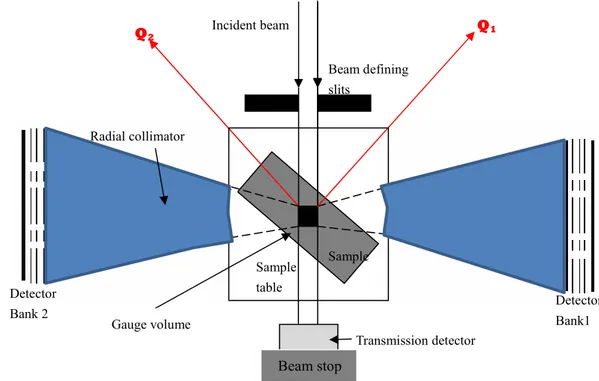
The ENGIN-X diffractometer has a flux distribution peaking at a neutron wavelength of around 2 Å. The sample position is at 50.0 m from the moderator. The instrument uses a 33.5 m long curved super-mirror guide followed by a 10.5 m long straight guide ending 1.5 m before the sample position. Scattered neutrons are recorded in two 90°- detector banks (Figure 1) containing 1200 detectors, on either side of the sample position, and positioned at a distance of 1.5 m from the sample. On ENGIN-X, one can define a small measurement volume (gauge volume) in the sample in the order of a few cubic millimetres. This is achieved by collimating the incident beam (width × height), and by using a radial collimator in front of the detectors to accept only neutrons from a certain length along the incident beam direction (Figure 1). Hence the diffraction pattern only contains neutrons scattered from the gauge volume, which need to be fully immersed in the sample in most cases to avoid pseudo strain. The sample can be systematically scanned in front of the neutron beam slits to establish chemical variation or strain maps.
To extract the information, such as strain or chemical composition the data from each detector bank is focused and normalized by the incoming flux distribution. Two
diffraction patterns, one for each 90-degree detector banks, are generated during measurements and represent two direction of stress. This data can be used for either single peak fitting or full pattern analysis through the Rietveld method with the General Structure Analysis System (GSAS) [21] which is used by the Open Genie calculation routine available on ENGIN-X.
Figure 1: Schematics of the data collection on ENGIN-X
For a neutron source with a neutron-flux time structure (as in the case of pulsed sources like ISIS), the TOF is measured. From the TOF it is possible to determine neutron velocity, and therefore its wavelength. The well known Bragg’s law can thus be re-written as a relation between the TOF of neutrons scattered from a set of planes in the sample and the spacing between these planes, dhkl as:
(TOF)hkl = (2mn/h)L dhkl sin Ө0 (1)
where mn is the neutron mass, L is the flight length of the pulsed beam from the moderator
to the sample and Ө0 is the fixed scattering angle.
2.2 Transmission Mode
ENGIN-X is also equipped with a Bragg edge transmission detector, which is a 2D pixellated area detector with an array of 10 × 10 scintillation detectors, each 2 × 2 mm2 with
a 0.5 mm pitch. It utilises the abrupt and well-defined increase in the transmitted intensity that occurs at certain neutron wavelength when no scattering can occur (at 2θ=180°). The step-like increases in transmitted intensity referred to as Bragg edges for particular hkl reflections appear in the TOF spectrum of the transmitted neutrons. Similar to diffraction peak analysis, a shift in the centre position of a Bragg edge corresponds to a change in the lattice spacing and hence enables the determination of strain in the direction of the incident beam. The transmission mode defines a sampling volume, which is the intersection of the incident beam and the sample, similar to neutron radiography. The transmission geometry opens up the possibility of using 2D detector to produce strain map.
A new approach to strain tomography based on Bragg edge measurement has recently been developed to analyze the residual strain fields by the de-convolution of unknown distributions of residual elastic strains [14]. Recent application of using Bragg
Radial collimator
Detector
Bank 2 Detector Bank1
Gauge volume Incident beam Q2 Q1 Sample Beam defining slits Sample table Transmission detector Beam stop
edge transmission detector for texture measurement can be also found in [15].
Currently, ISIS collaborates with the group from Space Sciences Laboratory University of California at Berkeley on the developments on the next generation of transmission detector with high spatial resolution for the new engineering beamline on Target Station 2 (TS2) IMAT [22]. The developments have been tested ENGIN-X. High spatial (~55 µm) and temporal (~1 µs) resolution neutron counting detectors have been achieved [16],[17], enabling the measurement of Bragg edges within each 55x55 µm2 pixel
simultaneously with the conventional neutron transmission radiography. Our previous proof-of-principle experiments performed on the same samples both in diffraction and transmission mode [18] confirmed the accuracy of the transmission mode technique. The capability to measure strain maps with ~100 µstrain accuracy and ~100 µm spatial resolution was demonstrated at the Engin-X beamline, providing unique measurement capabilities for engineering samples.
2.3 SScanSS – Virtual Instrument
The time spent with the routine tasks associated with sample positioning and machine control in particular for complex shaped samples were considered likely to take up a disproportionate amount of beamtime. To optimize strain scanning experiments ENGIN-X is equipped with virtual laboratory software named The Strain Scanning Simulation Software (SScanSS) [19,20]. The SScanSS software, which was developed by the Materials Engineering group at the Open University in close collaboration with the ENGIN-X instrument scientists, utilizes Virtual Reality (VR) computer techniques to provide tools for planning, optimizing and executing experiments. This software helps scientist and users to: i) visualize the instrument features and better understand the measurement procedure, ii) accurately and quickly position and orientate samples of arbitrary complexity, and iii) provide options for automatically optimizing other important experimental parameters, such as the measurement count time and collision prevention. The software generated interest at a number of other facilities and a comprehensive re-formulation was undertaken to enable implementation of other instruments and their positioning systems from within one code (such as Kowari, ANSTO and Vulcan, SNS). Additionally, the ENGIN-X instrument is equipped with two laser scanning inspection arms. The samples are scanned using the laser arm and the virtual model is created as input for SScanSS. The SScanSS software is used to specify the measurement points within the laser model and, following alignment on the instrument, calculates the coordinates of the measurement point in the instrument coordinate system and generates the control script required to execute the measurements.
Figure 2: Steps in applying tomography driven diffraction. (a) 3D model of the statue with defined plane; (b) selected measurement points in SScanSS; (c) sample on ENGIN-X [23].
Recently, the complementarity between neutron tomography and neutron diffraction was exploited in the new technique, “Tomography Driven Diffraction” (TDD) [23] and the
c b
SScanSS software was enhanced by this capability. The TDD has the advantage that the tomography dataset replaces the laser data and consequently useful information about internal and external geometry of the sample (see Figure 2) is acquired. This method can be suitable for other combined imaging and diffraction instruments.
3. Results and discussions
3.1 Current design and structure investigations
The ENGIN-X beamline has successfully been used to investigate residual strain/stress in various modern materials [7,10,15-16,18,23,25,26,28].
3.1.1 Investigation of nanostructured hydroxyapatite coatings
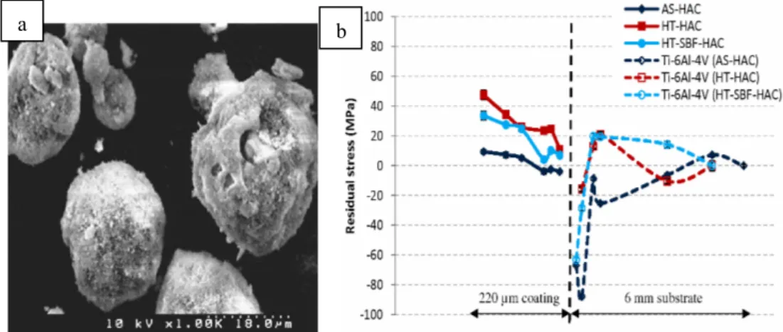
The structure property relationships of biomaterials such as hydroxyapatit coating (HAC) play an important role in the response of artificial implants [24]. The failure of an orthopaedic implant can be initiated by residual strains inherent to the HAC. Experiment was performed on ENGIN-X to improve current knowledge of the through-thickness residual strain profiles in the thermally sprayed hydroxyapatite coating/substrate system is therefore important in the development of a new generation of orthopaedic implants [25,26]. This study utilizes neutron diffraction for non-destructive through thickness strain measurements in nanostructured hydroxyapatite plasma sprayed coatings on a titanium alloy substrate (as-sprayed; heat treated; and heat treated then soaked in simulated body fluid (SBF)). The hydroxyapatite coatings (HAC) were 220 µm thick and were deposited on a substrate disc of 30 mm diameter and 6 mm thick commercial titanium alloy (Ti-6Al-4V). The experiments were conducted in vertical scan mode to measure through thickness residual strain profile of the coating-substrate system. The typical results of residual microstrain are shown in Figure 3. The results showed that the through thickness residual strains in all three coatings were different for different crystallographic planes but were on average tensile. It was also concluded that the heat-treatment and simulated body fluid exposure had a significant effect on the residual strain profiles in the top layers of the HAC.
Figure 3: a) SEM image of nanostructured hydroxyapatite (n-HAp) powder and b) residual stress profile of HA coatings and Ti-6Al-4Vsubstrate
3.2.1 Large scale welded pipe components
Ferritic-martensitic steels containing 9-12 wt. % chromium have been identified as the most promising class of materials for some of the key components in ultra-supercritical power plants. Unfortunately, the potential gains in plant efficiency that were offered by P91 and other 9-12 Cr steels have in practice been restricted by premature failures in welded joints through type IV cracking [27]. Research has shown that these failures are of
significant importance because they have occurred at a relatively early stage in component life (20,000 - 40,000 hours) and at lower operating temperatures than the maximum design temperature. One of the factors that might contribute to type IV cracking is residual stresses, since these are known to be large in the vicinity of welds.
The residual stresses in a P91 pipe girth weld were successfully measured before and after post weld heat treatment, with 3x3x3 mm3 gauge volume in a 25 mm thick pipe, as
shown on Figure 4a. Detailed residual maps distributions were established. It was found that, in both the as-welded and post-weld heat treated conditions, the highest tensile stresses resided near the outer boundary of the heat-affected zone (HAZ) [28,29], as shown for the hoop direction in the as-welded condition in Figure 4b.
Figure 4: Pipe circumferential weld (a) measuerements set up on ENGIN-X for axial direction and (b) through thickness contour map of hoop stress in as-welded condition [28].
3.3 Investigation of the crack propagation in stainless steel
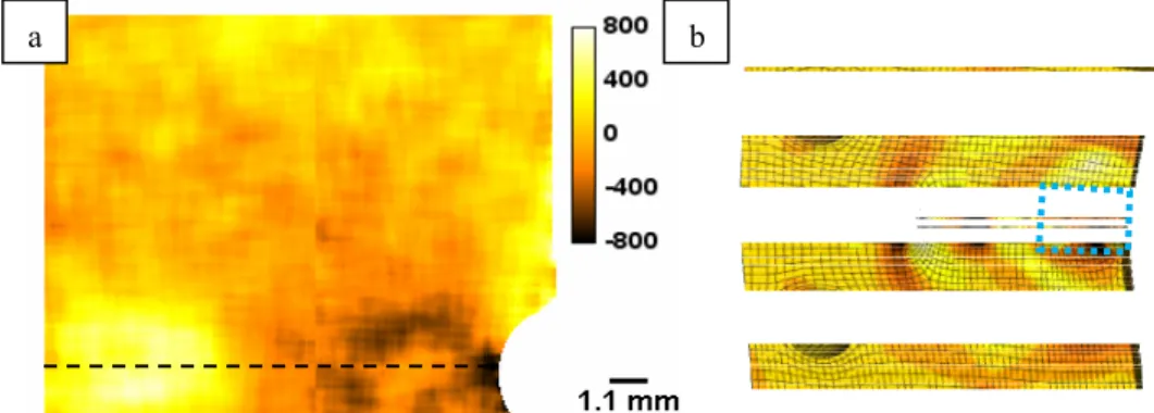
In addition to strain scanning in manufactured components, neutron diffraction is also useful for studies of fundamental material behaviour, such as fatigue and creep. As part of a study of how residual stress affects fatigue crack growth in 316 stainless steel, compact tension specimens incorporating strain misfit at the back face have been investigated in transmission-mode imaging on ENGIN-X [18]. A strain map around the crack tip was produces as shown in Figure 6a. Each sample was oriented with its side face normal to the beam. Strain was thus measured in the direction perpendicular to both the crack opening (loading) direction and the crack growth direction. Figure 5 shows both a strain map measured using Bragg edge fits to the neutron data from one sample, together with a finite element model of a sample in a similar state.
Figure 5: Out-of-plane strain in the cracked CT sample (a) measured by Bragg edge transmission within the area shown by the dashed rectangle in (b), shows a FEM of the whole
sample with the mid-thickness plane visible. The same colour scale applies to both the transmission measurement and the FEM [18].
a b
a b
Measurements location
The crack growth plane is a symmetry plane in the finite element model, allowing crack extension to be simulated in the model by releasing the boundary condition that ties the sample material to this plane. The measured region includes both the tip of the crack (up to several hundred microstrain) and a balancing residual stress near the back face, and both of these features show reasonable quantitative agreement with the finite element results. The spatial resolution of this detection system reveals sub-mm scale asymmetry of that strain field, not achievable with conventional neutron diffraction methods and not captured by the model, which assumes the crack opens symmetrically and consequently creates a symmetric residual stress field. This asymmetry in the measured data may arise from microstructural heterogeneity or crack surface roughness at this scale. Additionally, the crack tip strain field also occurs over a wider area in the measured data than in the model.
3.2 Investigations of historical samples
The ENGIN-X beamline has successfully been used to investigate strain, phase composition in various structures of historical [30-32, 36] and archaeological [33-35] samples.
3.2.1 Investigation of Japanese swords of the Koto age
Japanese swords making is probably one of the best examples of skills in historical metallurgy field in the history of mankind. A semi-empirical approach has been able to optimize the metallurgical characteristics of the components of the blade in order to produce the best results for every single element of the sword. The study focused on two Japanese long swords in order to determine the composition of the steel, the presence of phases related to the smelting (fayalite, wuestite, troilite) and the presence of oxides due to the mineralization (goethite, magnetite, hematite) [37-38]. The two swords investigated, pertain to two different traditions of the Koto Age: the Bizen (Kanesada school) and the Mino (Aoe school) of the Koto (Ancient sword) age [30-31]. The former developed as one of the two most ancient and was born in the southern part of Honshu Island while the latter developed in the Mino province. Both areas are rich in iron ore mines and developed under the protection of local nobles. Both the Mino and Bizen traditions were done according to their peculiar forging procedure.
Figure 6: a) Swords in supporting frame on ENGIN-X, set for transverse and normal measurements and b) comparison of axial microstrain near the edge of the two blades [31].
The results of the axial strains are shown which shows clear evidence of a change from negative strain values close to the tang to positive values in the upper parts of the swords along the axial direction (Figure 6). The Aoe blade has a less pronounced change that is instead very abrupt in the Kanesada one. This fact is induced by the quenching of the blade that is responsible for a modification of the curvature. The upper part is the one usually employed to strike blows which apply a pulsed force that is positive along the axial direction and negative along the transversal one. Since the residual strain distribution is
already positive (tensile) for both blades in the axial direction, the structure is in a permanent tensile state in a direction that is opposite to the one induced by the pulsed force of the blow. In this way the resilience of the edge along the axial direction is enhanced. This phenomenon was induced by quenching. The improved mechanical characteristics of the blade were probably achieved by a trial and error process. The strain profiles in the other two directions (transversal and normal) behave exactly in the opposite way as the axial one and this is induced by the elasticity of the material since an expansion in one direction usually implies a compression in at least another one. A negative or low positive value of the transversal strain in the monouchi area is an added value as it also increases resilience since the pulsed force is again applied in the same direction.
3.2.1 Investigation of gilded bronze relief from “The Gates to Paradise”
A gilded bronze relief, part of the East monumental Door located at the Battistero di
Firenze, manufactured by Lorenzo Ghiberti and named by Michelangelo as The Gates of Paradise, was studied by neutron diffraction at ENGIN-X (Figure 7a). The doors are one of
the greatest masterpieces of the Florentine Renaissance. The aim of this study was to perform a characterization of the bulk phase composition and residual strain distributions, in small areas at critical locations of the bronze relief. Moreover, the object presents a re-melting in the lower part that was suspected to be a repair due to possible defects during primary casting. Previous investigation using the neutron radiography method revealed a lighter area in the images. This fact supported the hypothesis that there is a cavity or a region with unknown inhomogeneous material, for example clay. These measurements helped to answer this intriguing question. The experimental setup for this investigation is shown in Figure 7 [36]. Results suggest that such a volume, located in the area from the base of the neck to the occipital lobe, is hollow thus excluding the presence of fusion clays. A set of measurements was also devoted to the study of the bronze peak-broadening and its strain trends as it shown on Figure 7b. Results showed that, near the base, the primary fusion is extended only to 7 mm under the gilding. Strain analysis additionally revealed a similar trend in re-melting and primary fusion. Along the axis of the cylinder-shaped base, a widening of crystal planes is present while along the radius a compression of the planes is present. Results, demonstrated the presence of a microsegregation of the bronze alloy in the re-melting area which is typical of as-cast alloy with higher cooling rates. This may suggest that the re-melting was only a filler material without any particular treatment. Primary melting, on the contrary, showed the sign of heat treatments, such as annealing, and re-crystallization: clues for a homogenization process.
Figure 7: a) Relief in supporting frame on ENGIN-X, set for a measurements in re-melting region and b) vertical strain scan through the thickness of the relief [36].
b a
4. Conclusions and future plans
The ENGIN-X beamline is well equipped to study residual strains/stresses in complex shape engineering components. The high resolution of the measurements allowed the detailed measurements in thin coatings, in front of crack tip, as well in heavy sections of pipe component and historical artifacts.
The ISIS team is constantly working on further improvements of our materials characterization capabilities. In order to enhance the neutron imaging capabilities at ISIS and to complement the existing materials analysis facilities, the first neutron tomography instrument at a pulsed neutron source is being designed for the ISIS Target Station 2 (TS2). The new instrument for materials science & engineering imaging, IMAT will be a state-of-the art combined instrument for cold neutron radiography and diffraction analysis for materials science, materials processing, and engineering studies. The instrument will provide the largest possible neutron flux available for imaging at ISIS and will allow medium-resolution neutron “colour” imaging and diffraction (strain scanning and texture during one experiment). The ability to perform imaging and diffraction studies on the same beamline with a single sample set-up will offer unprecedented opportunities for a new generation of neutron studies.
Acknowledgements
Experiments at the ISIS Pulsed Neutron and Muon Source were supported by a beamtime allocation from the Science and Technology Facilities Council. Authors would like to acknowledge all the co-investigators who were involved in the presented research and their names are reported in the reference papers. MEF is supported by a grant through The Open University from The Lloyd’s Register Educational Trust, an independent charity working to achieve advances in transportation, science, engineering and technology education, training and research worldwide for the benefit of all.
References
(1) Webster G.A., Wimpory, R.C., Journal of Neutron Research, 9 (2001) 281
(2) Jang J., Son D., Lee Y-H., Choi Y., Kwon D., Scripta Materialia, 48(6) (2003) 743 (3) Pang J.W.L., Preuss M., Withers P.J., Baxter G.J., Small C., Materials Science and
Engineering A, 356 (1-2) (2003) 405
(4) Owen R.A., Preston R.V., Withers P.J., Shercliff H.R., Webster P. J., Materials Science and Engineering A, 346 (1-2) (2003) 159
(5) Webster J., Ananthaviravakumar N., Hughes D.J., Mills G., Preston R.V., Shercliff H.R., Withers P.J., Applied Physics A 74 (2002) S1421
(6) Lorentzen T., Ibsø J. B., Materials Science and Eng. A, 197(2) (1995) 209
(7) Zhang S.Y., Godfrey E., Kockelman W., Paradowska A., Bull M.J., Korsunsky A.M., Abbey B., Xu P., Tomota Y., Liljedahl D., Zanellato O., Fitzpatrick M., Daymond M.R., Toda R.M., Holt R.A., Kelleher J., Siano S., Sansitisteban J., Materials Today, 12, 7-8 (2009) 78
(8) Paradowska A.M., Price J.W.H., Finlayson T.R., Lienert U., Walls P., Ibrahim R., Journal of Physics: Condensed Matter. 21 12 (2009) 124213
(9) ISO/TTA 3: 2001 Polycrystalline materials – Determination of residual stresses by Neutron Diffraction
(10) Santisteban, J.R., et al., J. Applied Crystallography 39 (2006) 812
(11) Joncour L.L., Panicaud B., Baczmanski A., Francois M., Braham C., Paradowska A.M., S. Wronski, R. Chiron, Mechanics of Materials, 42 (12) (2010) 1048
(12) Kisi E.H, Zhang J.F., Kirstein O., Riley D.P., Styles M.J. Paradowska A.M., J. Phys. Condensed Matter., 22 (2010) 162202
(13) Lee S. Y., Choo, Liaw P. K., Oliver E. C., Paradowska A. M., Klarstrom D. L., Scripta Materialia. 60, 10 (2009) 866
(14) Abbey B., Zhang S.Y., Vorster W.J.J., Korsunsky A., Procedia Engineering, 1 (2009) 185
(15) Boin M., Hilger A., Kardjilov N., Zhang S.Y., Oliver E.C., James J.A., Randau C., Wimpory R. C., Journal of Applied Crystallography 44 (2011) 1040
(16) Tremsin A.S., McPhate J.B., Vallerga J.V., Siegmund O.H.W., Feller W.B., Lehmann E., Dawson M., Nuclear Instruments and Methods in Physics Research Section A, 652 (2011) 400
(17) Tremsin A.S., McPhate J.B., Vallerga J.V., Siegmund O. H. W., Feller W. B., Bilheux H.Z., Molaison J.J., Tulk C.A, Crow L., Cooper R.G., Penumadu D., Journal of Physics: Conference Series 251 (2010) 012069
(18) Tremsin A.S., McPhate J.B., Steuwer A., Kockelmann W., Paradowska A. M, Kelleher J. F., Vallerga J. V., Siegmund O.H.W., Feller W.B., Strain, (2012) In press
(19) James J.A., Santisteban J.R., Edwards L., Daymond M.R., Physica B, Condensed Matter, 350 (2004) 743
(20) James J.A., Edwards L., Nuclear Instruments and Methods in Physics Research A, 571 (2007) 709
(21) Larson AC, von Dreele RB, General structure analysis system. Los Alamos National Laboratory Report LAUR (2004) 86
(22) Kockelmann W., et al., IMAT outline specifications, STFC (2009)
(23) Burca G., James J.A., Kockelmann W., Fitzpatrick M.E., Zhang S.Y., Hovind J., van Langh R., Nuclear Instruments and Methods in Physics Research Section A, 651 (2011) 229
(24) Leeuwenburgh S.C.G., Jansen J.A., Malda J., Dhert W.A., Rouwkema J., van Blitterswijk C.A., Kirkpatrick C.J., Williams D.F., Biomaterials 29, (2008) 3047 (25) Ahmed R., Faisal N.H., Paradowska A.M., Fitzpatrick M.E., Khor K.A., Journal of the
Mechanical Behaviour of Biomedical Materials 4, (2011) 2043
(26) Ahmed R., Faisal N.H., Knupfer S.M., Paradowska A.M., Fitzpatrick M.E., Khor K.A., Cizek J., Materials Science Forum 652, (2010) 309
(27) Francis J.A., Mazur W., Bhadeshia H.K.D.H., Materials Science and Technology, 22 (2006) 1387
(28) Paddea S., Francis J.A., Paradowska A.M., Bouchard P.J., Shibli I.A, 8th European Conference on Residual Stresses (ECRS8), 26-28 Jun 2010
(29) Paddea S., Francis J.A., Paradowska A.M., Bouchard P.J., Shibli I.A., Residual stress distributions in a P91 steel-pipe girth weld before and after post weld heat treatment. Materials Science and Engineering: A (2012) In press
(30) Grazzi F., Bartoli L., Civita F., Franci R., Paradowska A., Scherillo A., Zoppi M., J. Anal. At. Spectrom. 26, (2011) 1030
(31) Grazzi F., Bartoli L., Barzagli E., Civita F., Paradowska A., Scherillo A., Zoppi M., La Metallurgia Italiana 5 (2011) 13
(32) Festa G.., Kockelmann W., Kirfel A. and the Ancient Charm Collaboration. Archeometry Workshop, Hungary, Nr. 2008/1
(33) Kockelmann W., Siano S., Bartoli L., Visser D., Hallebeek P., Traum R., Linke R., Schreiner M., Kirfel A., Apl. Phys A 83, (2006) 175
(34) Postma H., Amkreutz L., Borella A., Clarijs M., Kamermans H., Kockelmann W., Paradowska A., Schillebeecks P., Visser D., Journal of Radioanalytical Nuclear Chemistry 283 (3) (2010) 641
(35) Caspi E.N., Shalev S., Shilstein S., Paradowska A.M., Kockelmann W., Levy Y., Journal of Physics: Conf. Ser. 251, (2010) 012047
(36) Festa G., Senesi R., Alessandroni M., Andreani C.,Vitali G., Porcinai S., Giusti A. M., Materna T., Paradowska A. M., Journal of Applied Physics, 109 (2011) 064908
(37) Sato K., The Japanese Sword: A Comprehensive Guide, Kodansha International (1997).
(38) Nagayama K., The Connoisseurs Book of Japanese Swords, Kodansha International (1997).
![Figure 2: Steps in applying tomography driven diffraction. (a) 3D model of the statue with defined plane; (b) selected measurement points in SScanSS; (c) sample on ENGIN-X [23]](https://thumb-eu.123doks.com/thumbv2/123dokorg/7591190.113381/4.892.295.807.850.1052/figure-applying-tomography-diffraction-defined-selected-measurement-sscanss.webp)
![Figure 6: a) Swords in supporting frame on ENGIN-X, set for transverse and normal measurements and b) comparison of axial microstrain near the edge of the two blades [31]](https://thumb-eu.123doks.com/thumbv2/123dokorg/7591190.113381/7.892.287.836.741.944/figure-swords-supporting-transverse-normal-measurements-comparison-microstrain.webp)
![Figure 7: a) Relief in supporting frame on ENGIN-X, set for a measurements in re-melting region and b) vertical strain scan through the thickness of the relief [36]](https://thumb-eu.123doks.com/thumbv2/123dokorg/7591190.113381/8.892.285.840.825.1076/figure-relief-supporting-measurements-melting-region-vertical-thickness.webp)
