Table of Contents
Preface . . . xiii
1. Getting Started . . . 1
1.1 Installing the Integrated Development Environment (IDE) 41.2 Setting Up the Arduino Board 6
1.3 Using the Integrated Development Environment (IDE) to Prepare
an Arduino Sketch 8
1.4 Uploading and Running the Blink Sketch 11
1.5 Creating and Saving a Sketch 13
1.6 Using Arduino 15
2. Making the Sketch Do Your Bidding . . . 19
2.1 Structuring an Arduino Program 20
2.2 Using Simple Primitive Types (Variables) 21
2.3 Using Floating-Point Numbers 23
2.4 Working with Groups of Values 25
2.5 Using Arduino String Functionality 28
2.6 Using C Character Strings 30
2.7 Splitting Comma-Separated Text into Groups 32
2.8 Converting a Number to a String 34
2.9 Converting a String to a Number 36
2.10 Structuring Your Code into Functional Blocks 38
2.11 Returning More Than One Value from a Function 41
2.12 Taking Actions Based on Conditions 44
2.13 Repeating a Sequence of Statements 45
2.14 Repeating Statements with a Counter 47
2.15 Breaking Out of Loops 49
2.16 Taking a Variety of Actions Based on a Single Variable 50
2.17 Comparing Character and Numeric Values 52
2.18 Comparing Strings 54
2.20 Performing Bitwise Operations 56
2.21 Combining Operations and Assignment 58
3. Using Mathematical Operators . . . 61
3.1 Adding, Subtracting, Multiplying, and Dividing 61
3.2 Incrementing and Decrementing Values 62
3.3 Finding the Remainder After Dividing Two Values 63
3.4 Determining the Absolute Value 64
3.5 Constraining a Number to a Range of Values 65
3.6 Finding the Minimum or Maximum of Some Values 66
3.7 Raising a Number to a Power 67
3.8 Taking the Square Root 68
3.9 Rounding Floating-Point Numbers Up and Down 68
3.10 Using Trigonometric Functions 69
3.11 Generating Random Numbers 70
3.12 Setting and Reading Bits 72
3.13 Shifting Bits 75
3.14 Extracting High and Low Bytes in an int or long 77
3.15 Forming an int or long from High and Low Bytes 78
4. Serial Communications . . . 81
4.1 Sending Debug Information from Arduino to Your Computer 86 4.2 Sending Formatted Text and Numeric Data from Arduino 894.3 Receiving Serial Data in Arduino 92
4.4 Sending Multiple Text Fields from Arduino in a Single Message 95 4.5 Receiving Multiple Text Fields in a Single Message in Arduino 98
4.6 Sending Binary Data from Arduino 101
4.7 Receiving Binary Data from Arduino on a Computer 105 4.8 Sending Binary Values from Processing to Arduino 107
4.9 Sending the Value of Multiple Arduino Pins 109
4.10 How to Move the Mouse Cursor on a PC or Mac 112
4.11 Controlling Google Earth Using Arduino 115
4.12 Logging Arduino Data to a File on Your Computer 121 4.13 Sending Data to Two Serial Devices at the Same Time 124 4.14 Receiving Serial Data from Two Devices at the Same Time 128 4.15 Setting Up Processing on Your Computer to Send
and Receive Serial Data 131
5. Simple Digital and Analog Input . . . 133
5.1 Using a Switch 136
5.2 Using a Switch Without External Resistors 139
5.3 Reliably Detecting the Closing of a Switch 141
5.4 Determining How Long a Switch Is Pressed 144
5.5 Reading a Keypad 149
5.6 Reading Analog Values 152
5.7 Changing the Range of Values 154
5.8 Reading More Than Six Analog Inputs 155
5.9 Displaying Voltages Up to 5V 158
5.10 Responding to Changes in Voltage 161
5.11 Measuring Voltages More Than 5V (Voltage Dividers) 162
6. Getting Input from Sensors . . . 165
6.1 Detecting Movement 167
6.2 Detecting Light 170
6.3 Detecting Motion (Integrating Passive Infrared Detectors) 171
6.4 Measuring Distance 173
6.5 Measuring Distance Accurately 176
6.6 Detecting Vibration 180
6.7 Detecting Sound 181
6.8 Measuring Temperature 185
6.9 Reading RFID Tags 187
6.10 Tracking the Movement of a Dial 190
6.11 Tracking the Movement of More Than One Rotary Encoder 193 6.12 Tracking the Movement of a Dial in a Busy Sketch 195
6.13 Using a Mouse 197
6.14 Getting Location from a GPS 201
6.15 Detecting Rotation Using a Gyroscope 206
6.16 Detecting Direction 208
6.17 Getting Input from a Game Control Pad (PlayStation) 211
6.18 Reading Acceleration 213
7. Visual Output . . . 217
7.1 Connecting and Using LEDs 220
7.2 Adjusting the Brightness of an LED 223
7.3 Driving High-Power LEDs 224
7.4 Adjusting the Color of an LED 226
7.5 Sequencing Multiple LEDs: Creating a Bar Graph 229
7.6 Sequencing Multiple LEDs: Making a Chase Sequence (Knight
Rider) 232
7.7 Controlling an LED Matrix Using Multiplexing 234
7.8 Displaying Images on an LED Matrix 236
7.9 Controlling a Matrix of LEDs: Charlieplexing 239
7.10 Driving a 7-Segment LED Display 245
7.11 Driving Multidigit, 7-Segment LED Displays: Multiplexing 248 7.12 Driving Multidigit, 7-Segment LED Displays Using MAX7221 Shift
7.13 Controlling an Array of LEDs by Using MAX72xx Shift Registers 253 7.14 Increasing the Number of Analog Outputs Using PWM Extender
Chips (TLC5940) 255
7.15 Using an Analog Panel Meter As a Display 259
8. Physical Output . . . 261
8.1 Controlling the Position of a Servo 264
8.2 Controlling One or Two Servos with a Potentiometer
or Sensor 266
8.3 Controlling the Speed of Continuous Rotation Servos 267
8.4 Controlling Servos from the Serial Port 269
8.5 Driving a Brushless Motor (Using a Hobby Speed Controller) 271
8.6 Controlling Solenoids and Relays 272
8.7 Making an Object Vibrate 273
8.8 Driving a Brushed Motor Using a Transistor 276
8.9 Controlling the Direction of a Brushed Motor
with an H-Bridge 277
8.10 Controlling the Direction and Speed of a Brushed Motor with an
H-Bridge 280
8.11 Using Sensors to Control the Direction and Speed of Brushed
Motors (L293 H-Bridge) 282
8.12 Driving a Bipolar Stepper Motor 287
8.13 Driving a Bipolar Stepper Motor (Using the EasyDriver Board) 290
8.14 Driving a Unipolar Stepper Motor (ULN2003A) 293
9. Audio Output . . . 297
9.1 Playing Tones 299
9.2 Playing a Simple Melody 301
9.3 Generating More Than One Simultaneous Tone 303
9.4 Generating Audio Tones and Fading an LED 305
9.5 Playing a WAV File 308
9.6 Controlling MIDI 311
9.7 Making an Audio Synthesizer 314
10. Remotely Controlling External Devices . . . 317
10.1 Responding to an Infrared Remote Control 318
10.2 Decoding Infrared Remote Control Signals 321
10.3 Imitating Remote Control Signals 324
10.4 Controlling a Digital Camera 327
10.5 Controlling AC Devices by Hacking a Remote Controlled Switch 330
11. Using Displays . . . 333
11.1 Connecting and Using a Text LCD Display 334
11.2 Formatting Text 337
11.3 Turning the Cursor and Display On or Off 340
11.4 Scrolling Text 342
11.5 Displaying Special Symbols 345
11.6 Creating Custom Characters 347
11.7 Displaying Symbols Larger Than a Single Character 349 11.8 Displaying Pixels Smaller Than a Single Character 352
11.9 Connecting and Using a Graphical LCD Display 355
11.10 Creating Bitmaps for Use with a Graphical Display 359
11.11 Displaying Text on a TV 361
12. Using Time and Dates . . . 367
12.1 Creating Delays 367
12.2 Using millis to Determine Duration 368
12.3 More Precisely Measuring the Duration of a Pulse 372
12.4 Using Arduino As a Clock 373
12.5 Creating an Alarm to Periodically Call a Function 380
12.6 Using a Real-Time Clock 384
13. Communicating Using I2C and SPI . . . 389
13.1 Controlling an RGB LED Using the BlinkM Module 392
13.2 Using the Wii Nunchuck Accelerometer 397
13.3 Interfacing to an External Real-Time Clock 401
13.4 Adding External EEPROM Memory 404
13.5 Reading Temperature with a Digital Thermometer 408
13.6 Driving Four 7-Segment LEDs Using Only Two Wires 412
13.7 Integrating an I2C Port Expander 416
13.8 Driving Multidigit, 7-Segment Displays Using SPI 418 13.9 Communicating Between Two or More Arduino Boards 421
14. Wireless Communication . . . 425
14.1 Sending Messages Using Low-Cost Wireless Modules 425 14.2 Connecting Arduino to a ZigBee or 802.15.4 Network 43114.3 Sending a Message to a Particular XBee 438
14.4 Sending Sensor Data Between XBees 440
14.5 Activating an Actuator Connected to an XBee 446
15. Ethernet and Networking . . . 451
15.1 Setting Up the Ethernet Shield 453
15.2 Obtaining Your IP Address Automatically 455
15.3 Resolving Hostnames to IP Addresses (DNS) 458
15.4 Requesting Data from a Web Server 462
15.6 Setting Up an Arduino to Be a Web Server 469
15.7 Handling Incoming Web Requests 471
15.8 Handling Incoming Requests for Specific Pages 474
15.9 Using HTML to Format Web Server Responses 479
15.10 Serving Web Pages Using Forms (POST) 483
15.11 Serving Web Pages Containing Large Amounts of Data 486
15.12 Sending Twitter Messages 493
15.13 Sending and Receiving Simple Messages (UDP) 496
15.14 Getting the Time from an Internet Time Server 502
15.15 Monitoring Pachube Feeds 507
15.16 Sending Information to Pachube 510
16. Using, Modifying, and Creating Libraries . . . 515
16.1 Using the Built-in Libraries 515
16.2 Installing Third-Party Libraries 517
16.3 Modifying a Library 518
16.4 Creating Your Own Library 522
16.5 Creating a Library That Uses Other Libraries 527
17. Advanced Coding and Memory Handling . . . 531
17.1 Understanding the Arduino Build Process 532
17.2 Determining the Amount of Free and Used RAM 535
17.3 Storing and Retrieving Numeric Values in Program Memory 537 17.4 Storing and Retrieving Strings in Program Memory 540
17.5 Using #define and const Instead of Integers 542
17.6 Using Conditional Compilations 543
18. Using the Controller Chip Hardware . . . 547
18.1 Storing Data in Permanent EEPROM Memory 551
18.2 Using Hardware Interrupts 554
18.3 Setting Timer Duration 557
18.4 Setting Timer Pulse Width and Duration 559
18.5 Creating a Pulse Generator 562
18.6 Changing a Timer’s PWM Frequency 565
18.7 Counting Pulses 567
18.8 Measuring Pulses More Accurately 569
18.9 Measuring Analog Values Quickly 571
18.10 Reducing Battery Drain 572
18.11 Setting Digital Pins Quickly 574
A. Electronic Components . . . 579
B. Using Schematic Diagrams and Data Sheets . . . 585
x | Table of ContentsC. Building and Connecting the Circuit . . . 591
D. Tips on Troubleshooting Software Problems . . . 595
E. Tips on Troubleshooting Hardware Problems . . . 599
F. Digital and Analog Pins . . . 603
G. ASCII and Extended Character Sets . . . 607
CHAPTER 1
Getting Started
1.0 Introduction
The Arduino environment has been designed to be easy to use for beginners who have no software or electronics experience. With Arduino, you can build objects that can respond to and/or control light, sound, touch, and movement. Arduino has been used to create an amazing variety of things, including musical instruments, robots, light sculptures, games, interactive furniture, and even interactive clothing.
If you’re not a beginner, please feel free to skip ahead to recipes that interest you.
Arduino is used in many educational programs around the world, particularly by de-signers and artists who want to easily create prototypes but do not need a deep under-standing of the technical details behind their creations. Because it is designed to be used by nontechnical people, the software includes plenty of example code to demonstrate how to use the Arduino board’s various facilities.
Though it is easy to use, Arduino’s underlying hardware works at the same level of sophistication that engineers employ to build embedded devices. People already work-ing with microcontrollers are also attracted to Arduino because of its agile development capabilities and its facility for quick implementation of ideas.
Arduino is best known for its hardware, but you also need software to program that hardware. Both the hardware and the software are called “Arduino.” The combination enables you to create projects that sense and control the physical world. The software is free, open source, and cross-platform. The boards are inexpensive to buy, or you can build your own (the hardware designs are also open source). In addition, there is an active and supportive Arduino community that is accessible worldwide through the Arduino forums and the wiki (known as the Arduino Playground). The forums and the
wiki offer project development examples and solutions to problems that can provide inspiration and assistance as you pursue your own projects.
The recipes in this chapter will get you started by explaining how to set up the devel-opment environment and how to compile and run an example sketch.
Source code containing computer instructions for controlling Arduino functionality is usually referred to as a sketch in the Arduino community. The word sketch will be used throughout this book to refer to Arduino program code.
The Blink sketch, which comes with Arduino, is used as an example for recipes in this chapter, though the last recipe in the chapter goes further by adding sound and col-lecting input through some additional hardware, not just blinking the light built into the board. Chapter 2 covers how to structure a sketch for Arduino and provides an introduction to programming.
If you already know your way around Arduino basics, feel free to jump forward to later chapters. If you’re a first-time Arduino user, patience in these early recipes will pay off with smoother results later.
Arduino Software
Software programs, called sketches, are created on a computer using the Arduino inte-grated development environment (IDE). The IDE enables you to write and edit code and convert this code into instructions that Arduino hardware understands. The IDE also transfers those instructions to the Arduino board (a process called uploading).
Arduino Hardware
The Arduino board is where the code you write is executed. The board can only control and respond to electricity, so specific components are attached to it to enable it to interact with the real world. These components can be sensors, which convert some aspect of the physical world to electricity so that the board can sense it, or actuators, which get electricity from the board and convert it into something that changes the world. Examples of sensors include switches, accelerometers, and ultrasound distance sensors. Actuators are things like lights and LEDs, speakers, motors, and displays. There are a variety of official boards that you can use with Arduino software and a wide range of Arduino-compatible boards produced by members of the community. The most popular boards contain a USB connector that is used to provide power and connectivity for uploading your software onto the board. Figure 1-1 shows a basic board, the Arduino Uno.
See Also
An overview of Arduino boards: http://www.arduino.cc/en/Main/Hardware.
Online guides for getting started with Arduino are available at http://arduino.cc/en/ Guide/Windows for Windows, http://arduino.cc/en/Guide/MacOSX for Mac OS X, and http://www.arduino.cc/playground/Learning/Linux for Linux.
Figure 1-1. Basic board: the Arduino Uno
1.1 Installing the Integrated Development Environment (IDE)
Problem
You want to install the Arduino development environment on your computer.
Solution
The Arduino software for Windows, Mac, and Linux can be downloaded from http:// arduino.cc/en/Main/Software.
The Windows download is a ZIP file. Unzip the file to any convenient directory— Program Files/Arduino is a sensible place.
A free utility for unzipping files, called 7-Zip, can be downloaded from
http://www.7-zip.org/.
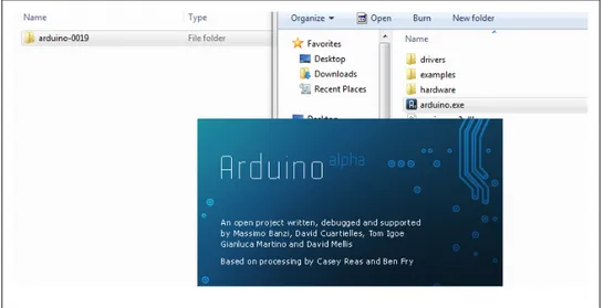
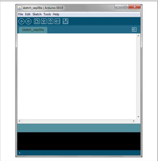
Unzipping the file will create a folder named Arduino-00<nn> (where <nn> is the ver-sion number of the Arduino release you downloaded). The directory contains the executable file (named Arduino.exe), along with various other files and folders. Double-click the Arduino.exe file and the splash screen should appear (see Figure 1-2), followed by the main program window (see Figure 1-3). Be patient, as it can take some time for the software to load.
The Arduino download for the Mac is a disk image (.dmg); double-click the file when the download is complete. The image will mount (it will appear like a memory stick on the desktop). Inside the disk image is the Arduino application. Copy this to some-where convenient—the Applications folder is a sensible place. Double-click the appli-cation once you have copied it over (it is not a good idea to run it from the disk image). The splash screen will appear, followed by the main program window.
Linux installation varies depending on the Linux distribution you are using. See the Arduino wiki for information (http://www.arduino.cc/playground/Learning/Linux). To enable the Arduino development environment to communicate with the board, you need to install drivers.
Figure 1-3. Arduino IDE main window (version 0019 in Windows 7)
On Windows, use the USB cable to connect your PC and the Arduino board and wait for the Found New Hardware Wizard to appear. If you are using Windows Vista or Windows 7 and are online, you can let the wizard search for drivers and they will install automatically. On Windows XP, you should specify the location of the drivers. Use the file selector to navigate to the drivers directory, located in the directory where you unzipped the Arduino files. When the driver has installed, the Found New Hardware Wizard will appear again, saying a new serial port has been found. Follow the same process as before.
It is important that you go through the sequence of steps to install the drivers two times, or the software will not be able to communicate with the board.
On the Mac, the latest Arduino boards, such as the Uno, can be used without additional drivers, but if you are using earlier boards, you will need to install driver software. There is a package named FTDIUSBSerialDriver, with a range of numbers after it, inside the disk image. Double-click this and the installer will take you through the process. You will need to know an administrator password to complete the process.
On Linux, most distributions have the driver already installed, but follow the Linux link given in this chapter’s introduction for specific information for your distribution.
Discussion
If the software fails to start, check the troubleshooting section of the Arduino website, http://arduino.cc/en/Guide/Troubleshooting, for help solving installation problems.
See Also
Online guides for getting started with Arduino are available at http://arduino.cc/en/ Guide/Windows for Windows, http://arduino.cc/en/Guide/MacOSX for Mac OS X, and http://www.arduino.cc/playground/Learning/Linux for Linux.
1.2 Setting Up the Arduino Board
Problem
You want to power up a new board and verify that it is working.
Solution
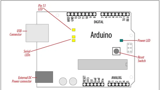
Plug the board into a USB port on your computer and check that the green LED power indicator on the board illuminates. Standard Arduino boards (Uno, Duemilanove, and Mega) have a green LED power indicator located near the reset switch.
An orange LED near the center of the board (labeled “Pin 13 LED” in Figure 1-4) should flash on and off when the board is powered up (boards come from the factory preloaded with software to flash the LED as a simple check that the board is working).
Figure 1-4. Basic Arduino board (Uno and Duemilanove)
Discussion
If the power LED does not illuminate when the board is connected to your computer, the board is probably not receiving power.
The flashing LED (connected to digital output pin 13) is being controlled by code running on the board (new boards are preloaded with the Blink example sketch). If the pin 13 LED is flashing, the sketch is running correctly, which means the chip on the board is working. If the green power LED is on but the pin 13 LED is not flashing, it could be that the factory code is not on the chip; follow the instructions in Rec-ipe 1.3 to load the Blink sketch onto the board to verify that the board is working. If you are not using a standard board, it may not have a built-in LED on pin 13, so check the documentation for details of your board.
See Also
Online guides for getting started with Arduino are available at http://arduino.cc/en/ Guide/Windows for Windows, http://arduino.cc/en/Guide/MacOSX for Mac OS X, and http://www.arduino.cc/playground/Learning/Linux for Linux.
A troubleshooting guide can be found at http://arduino.cc/en/Guide/Troubleshooting. 1.2 Setting Up the Arduino Board | 7
1.3 Using the Integrated Development Environment (IDE) to
Prepare an Arduino Sketch
Problem
You want to get a sketch and prepare it for uploading to the board.
Solution
Use the Arduino IDE to create, open, and modify sketches that define what the board will do. You can use buttons along the top of the IDE to perform these actions (shown in Figure 1-5), or you can use the menus or keyboard shortcuts (shown in Figure 1-6). The Sketch Editor area is where you view and edit code for a sketch. It supports com-mon text editing keys such as Ctrl-F (⌘+F on a Mac) for find, Ctrl-Z (⌘+Z on a Mac) for undo, Ctrl-C (⌘+C on a Mac) to copy highlighted text, and Ctrl-V (⌘+V on a Mac) to paste highlighted text.
Figure 1-6 shows how to load the Blink sketch (the sketch that comes preloaded on a new Arduino board).
After you’ve started the IDE, go to the File→Examples menu and select 1.Basics→Blink, as shown in Figure 1-6. The code for blinking the built-in LED will be displayed in the Sketch Editor window (refer to Figure 1-5).
Before the code can be sent to the board, it needs to be converted into instructions that can be read and executed by the Arduino controller chip; this is called compiling. To do this, click the compile button (the top-left button with a triangle inside), or select Sketch→Verify/Compile.
You should see a message that reads “Compiling...” in the message area below the text editing window. After a second or two, a message that reads “Done Compiling” will appear. The black console area will contain the following additional message:
Binary sketch size: 1008 bytes (of a 32256 byte maximum)
The exact message may differ depending on the Arduino version; it is telling you the size of the sketch and the maximum size that your board can accept.
Figure 1-5. Arduino IDE
Discussion
Source code for Arduino is called a sketch. The process that takes a sketch and converts it into a form that will work on the board is called compilation. The IDE uses a number of command-line tools behind the scenes to compile a sketch. For more information on this, see Recipe 17.1.
Figure 1-6. IDE menu (selecting the Blink example sketch)
The final message telling you the size of the sketch indicates how much program space is needed to store the controller instructions on the board. If the size of the compiled sketch is greater than the available memory on the board, the following error message is displayed:
Sketch too big; see http://www.arduino.cc/en/Guide/Troubleshooting#size for tips on reducing it.
If this happens, you need to make your sketch smaller to be able to put it on the board, or get a board with higher capacity.
If there are errors in the code, the compiler will print one or more error messages in the console window. These messages can help identify the error—see Appendix D on soft-ware errors for troubleshooting tips.
To prevent accidental overwriting of the examples, the Arduino IDE does not allow you to save changes to the provided example sketches. You must rename them using the Save As menu option. You can save sketches you write yourself with the Save button (see Recipe 1.5).
As you develop and modify a sketch, you should also consider using the File→Save As menu option and using a different name or version number regularly so that as you implement each bit, you can go back to an older version if you need to.
Code uploaded onto the board cannot be downloaded back onto your computer. Make sure you save your sketch code on your computer. You cannot save changes back to the example files; you need to use Save As and give the changed file another name.
See Also
Recipe 1.5 shows an example sketch. Appendix D has tips on troubleshooting software problems.
1.4 Uploading and Running the Blink Sketch
Problem
You want to transfer your compiled sketch to the Arduino board and see it working.
Solution
Connect your Arduino board to your computer using the USB cable. Load the Blink sketch into the IDE as described in Recipe 1.3.
Next, select Tools→Board from the drop-down menu and select the name of the board you have connected (if it is the standard Uno board, it is probably the first entry in the board list).
Now select Tools→Serial Port. You will get a drop-down list of available serial ports on your computer. Each machine will have a different combination of serial ports, de-pending on what other devices you have used with your computer.
On Windows, they will be listed as numbered COM entries. If there is only one entry, select it. If there are multiple entries, your board will probably be the last entry.
On the Mac, your board will be listed twice if it is an Uno board:
/dev/tty.usbmodem-XXXXXXX /dev/cu.usbmodem-XXXXXXX
If you have an older board, it will be listed as follows:
/dev/tty.usbserial-XXXXXXX /dev/cu.usbserial-XXXXXXX
Each board will have different values for XXXXXXX. Select either entry.
Click on the upload button (in Figure 1-5, it’s the fifth button from the left), or choose File→Upload to I/O board.
The software will compile the code, as in Recipe 1.3. After the software is compiled, it is uploaded to the board. If you look at your board, you will see the LED stop flashing, and two lights (labeled as Serial LEDs in Figure 1-4) just below the previously flashing LED should flicker for a couple of seconds as the code uploads. The original light should then start flashing again as the code runs.
Discussion
For the IDE to send the compiled code to the board, the board needs to be plugged into the computer, and you need to tell the IDE which board and serial port you are using.
When an upload starts, whatever sketch is running on the board is stopped (if you were running the Blink sketch, the LED will stop flashing). The new sketch is uploaded to the board, replacing the previous sketch. The new sketch will start running when the upload has successfully completed.
Older Arduino boards and some compatibles do not automatically in-terrupt the running sketch to initiate upload. In this case, you need to press the Reset button on the board just after the software reports that it is done compiling (when you see the message about the size of the sketch). It may take a few attempts to get the timing right between the end of the compilation and pressing the Reset button.
The IDE will display an error message if the upload is not successful. Problems are usually due to the wrong board or serial port being selected or the board not being plugged in.
If you have trouble identifying the correct port on Windows, try unplugging the board and then selecting Tools→Serial Port to see which COM port is no longer on the display list. Another approach is to select the ports, one by one, until you see the lights on the board flicker to indicate that the code is uploading.
See Also
The Arduino troubleshooting page: http://www.arduino.cc/en/Guide/Troubleshooting
1.5 Creating and Saving a Sketch
Problem
You want to create a sketch and save it to your computer.
Solution
To open an editor window ready for a new sketch, launch the IDE (see Recipe 1.3), go to the File menu, and select New. Paste the following code into the Sketch Editor win-dow (it’s similar to the Blink sketch, but the blinks last twice as long):
const int ledPin = 13; // LED connected to digital pin 13 void setup() { pinMode(ledPin, OUTPUT); } void loop() {
digitalWrite(ledPin, HIGH); // set the LED on delay(2000); // wait for two seconds digitalWrite(ledPin, LOW); // set the LED off delay(2000); // wait for two seconds }
Compile the code by clicking the compile button (the top-left button with a triangle inside), or select Sketch→Verify/Compile (see Recipe 1.3).
Upload the code by clicking on the upload button, or choose File→Upload to I/O board (see Recipe 1.4). After uploading, the LED should blink, with each flash lasting two seconds.
You can save this sketch to your computer by clicking the Save button, or select File→Save.
You can save the sketch using a new name by selecting the Save As menu option. A dialog box will open where you can enter the filename.
Discussion
When you save a file in the IDE, a standard dialog box for the operating system will open. It suggests that you save the sketch to a folder called Arduino in your My Docu-ments folder (or your DocuDocu-ments folder on a Mac). You can replace the default sketch
name with a meaningful name that reflects the purpose of your sketch. Click Save to save the file.
The default name is the word sketch followed by the current date. Se-quential letters starting from a are used to distinguish sketches created on the same day. Replacing the default name with something meaning-ful helps you to identify the purpose of a sketch when you come back to it later.
If you use characters that the IDE does not allow (e.g., the space character), the IDE will automatically replace these with valid characters.
Arduino sketches are saved as plain text files with the extension .pde. They are auto-matically saved in a folder with the same name as the sketch.
You can save your sketches to any folder on your computer, but if you use the default folder (the Arduino folder in your Documents folder) your sketches will automatically appear in the Sketchbook menu of the Arduino software and be easier to locate.
If you have edited one of the examples from the Arduino download, you will not be able to save the changed file using the same filename. This preserves the standard examples intact. If you want to save a modified example, you will need to select another location for the sketch.
After you have made changes, you will see a dialog box asking if you want to save the sketch when a sketch is closed.
The § symbol following the name of the sketch in the top bar of the IDE window indicates that the sketch code has changes that have not yet been saved on the computer. This symbol is removed when you save the sketch.
The Arduino software does not provide any kind of version control, so if you want to be able to revert to older versions of a sketch, you can use Save As regularly and give each revision of the sketch a slightly different name.
Frequent compiling as you modify or add code is a good way to check for errors as you write your code. It will be easier to find and fix any errors because they will usually be associated with what you have just written.
Once a sketch has been uploaded onto the board there is no way to download it back to your computer. Make sure you save any changes to your sketches that you want to keep.
If you open sketches you get from other people that are not in a folder with the same name as the sketch, the IDE will tell you and you can click OK to put them in a folder with the same name.
Sketches must be located in a folder with the same name as the sketch. The IDE will create the folder automatically when you save a new sketch.
1.6 Using Arduino
Problem
You want to get started with a project that is easy to build and fun to use.
Solution
This recipe provides a taste of some of the techniques that are covered in detail in later chapters.
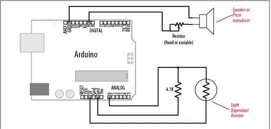
The sketch is based on the LED blinking code from the previous recipe, but instead of using a fixed delay, the rate is determined by a light-sensitive sensor called a light de-pendent resistor or LDR (see Recipe 6.2). Wire the LDR as shown in Figure 1-7.
Figure 1-7. Arduino with light dependent resistor
The following sketch reads the light level of an LDR connected to analog pin 0. The light level striking the LDR will change the blink rate of the internal LED connected to pin 13:
const int ledPin = 13; // LED connected to digital pin 13 const int sensorPin = 0; // connect sensor to analog input 0 void setup()
{
pinMode(ledPin, OUTPUT); // enable output on the led pin }
void loop() {
int rate = analogRead(sensorPin); // read the analog input Serial.println(rate);
rate = map(rate, 200,800,minDuration, maxDuration); // convert to blink rate digitalWrite(ledPin, HIGH); // set the LED on
delay(rate); // wait duration dependent on light level digitalWrite(ledPin, LOW); // set the LED off
delay(rate); }
Discussion
The value of the 4.7K resistor is not critical. Anything from 1K to 10K can be used. The light level on the LDR will change the voltage level on analog pin 0. The analogRead command (see Chapter 6) provides a value that ranges from around 200 when the LDR is dark to 800 or so when it is very bright. This value determines the duration of the LED on and off times, so the blink rate increases with light intensity.
You can scale the blink rate by using the Arduino map function as follows:
const int ledPin = 13; // LED connected to digital pin 13 const int sensorPin = 0; // connect sensor to analog input 0 // the next two lines set the min and max delay between blinks const int minDuration = 100; // minimum wait between blinks const int maxDuration = 1000; // maximum wait between blinks void setup()
{
pinMode(ledPin, OUTPUT); // enable output on the led pin }
void loop() {
int rate = analogRead(sensorPin); // read the analog input // the next line scales the blink rate between the min and max values rate = map(rate, 200,800,minDuration, maxDuration); // convert to blink rate digitalWrite(ledPin, HIGH); // set the LED on
delay(rate); // wait duration dependent on light level digitalWrite(ledPin, LOW); // set the LED off
delay(rate); }
If you want to view the value of the rate variable on your computer, you can print this to the Arduino Serial Monitor as shown in the revised loop code that follows. The sketch will display the blink rate in the Serial Monitor. You open the Serial Monitor window in the Arduino IDE (see Chapter 4 for more on using the Serial Monitor):
const int ledPin = 13; // LED connected to digital pin 13 const int sensorPin = 0; // connect sensor to analog input 0 // the next two lines set the min and max delay between blinks const int minDuration = 100; // minimum wait between blinks const int maxDuration = 1000; // maximum wait between blinks void setup()
{
pinMode(ledPin, OUTPUT); // enable output on the led pin Serial.begin(9600); // initialize Serial
}
void loop() {
int rate = analogRead(sensorPin); // read the analog input // the next line scales the blink rate between the min and max values rate = map(rate, 200,800,minDuration, maxDuration); // convert to blink rate Serial.println(rate); // print rate to serial monitor
digitalWrite(ledPin, HIGH); // set the LED on
delay(rate); // wait duration dependent on light level digitalWrite(ledPin, LOW); // set the LED off
delay(rate); }
You can use the LDR to control the pitch of a sound by connecting a small speaker to the pin, as shown in Figure 1-8.
Figure 1-8. Connections for a speaker with the LDR circuit
You will need to increase the on/off rate on the pin to a frequency in the audio spectrum. This is achieved, as shown in the following code, by dividing the rate by 100 in the line after the map function:
const int ledPin = 13; // LED connected to digital pin 13 const int sensorPin = 0; // connect sensor to analog input 0 const int minDuration = 100; // minimum wait between blinks const int maxDuration = 1000; // maximum wait between blinks void setup()
{
pinMode(ledPin, OUTPUT); // enable output on the led pin }
void loop() {
int sensorReading = analogRead(sensorPin); // read the analog input int rate = map(sensorReading, 200,800,minDuration, maxDuration); rate = rate / 100; // add this line for audio frequency digitalWrite(ledPin, HIGH); // set the LED on
delay(rate); // wait duration dependent on light level digitalWrite(ledPin, LOW); // set the LED off
delay(rate); }
See Also
CHAPTER 2
Making the Sketch Do Your Bidding
2.0 Introduction
Though much of an Arduino project will involve integrating the Arduino board with supporting hardware, you need to be able to tell the board what to do with the rest of your project. This chapter introduces core elements of Arduino programming, showing nonprogrammers how to use common language constructs and providing an overview of the language syntax for readers who are not familiar with C or C++, the language being used.
Since making the examples interesting requires making Arduino do something, the recipes use physical capabilities of the board that are explained in detail in later chap-ters. If any of the code in this chapter is not clear, feel free to jump forward, particularly to Chapter 4 for more on serial output and Chapter 5 for more on using digital and analog pins. You don’t need to understand all the code in the examples, though, to see how to perform the specific capabilities that are the focus of the recipes. Here are some of the more common functions used in the examples that are covered in the next few chapters:
Serial.println(value);
Prints the value to the Serial Monitor on your computer; see Recipe 4.1
pinMode(pin, mode);
Configures a digital pin to read (input) or write (output) a digital value; see the
introduction to Chapter 5
digitalRead(pin);
Reads a digital value (HIGH or LOW) on a pin set for input; see Recipe 5.1
digitalWrite(pin, value);
Writes the digital value (HIGH or LOW) to a pin set for output; see Recipe 5.1
19 D o w nl oa d fr om W ow ! eB oo k < w w w .w ow eb oo k. co m >
2.1 Structuring an Arduino Program
Problem
You are new to programming and want to understand the building blocks of an Arduino program.
Solution
Programs for Arduino are usually referred to as sketches, to emphasize the agile nature of development. The terms sketch and program are interchangeable. Sketches contain code—the instructions the board will carry out. Code that needs to run only once (such as to set up the board for your application) should be placed in the setup function. Code to be run continuously after the initial setup has finished goes into the loop func-tion. Here is a typical sketch:
const int ledPin = 13; // LED connected to digital pin 13 // The setup() method runs once, when the sketch starts void setup()
{
pinMode(ledPin, OUTPUT); // initialize the digital pin as an output }
// the loop() method runs over and over again, void loop()
{
digitalWrite(ledPin, HIGH); // turn the LED on delay(1000); // wait a second digitalWrite(ledPin, LOW); // turn the LED off delay(1000); // wait a second }
When the board finishes uploading the code, or is turned on once it contains this code, it starts at the top of the sketch and carries out the instructions sequentially. It runs the code in setup once and then goes through the code in loop. When it gets to the end of loop (marked by the closing bracket, }) it goes back to the beginning of loop.
Discussion
This example continuously flashes an LED by writing HIGH and LOW outputs to a pin. See Chapter 5 to learn more about using Arduino pins. When the sketch begins, the code in setup sets the pin mode (so it’s capable of lighting an LED). After the code in setup is completed, the code in loop is repeatedly called (to flash the LED) for as long as the Arduino board is powered on.
You don’t need to know this to write Arduino sketches, but experienced C/C++ pro-grammers may wonder where the expected main() entry point function has gone. It’s there, but it’s hidden under the covers by the Arduino build environment. The build
process creates an intermediate file that includes the sketch code and the following additional statements: int main(void) { init(); setup(); for (;;) loop(); return 0; }
The first thing that happens is a call to an init() function that initializes the Arduino hardware. Next, the sketch’s setup() function is called. Finally, the loop() function is called over and over. Because the for loop never terminates, the return statement is never executed.
See Also
Chapter 17 and http://www.arduino.cc/en/Hacking/BuildProcess provide more on the build process.
2.2 Using Simple Primitive Types (Variables)
Problem
Arduino has different types of variables to efficiently represent values. You want to know how to select and use these Arduino data types.
Solution
Although the int (short for integer, a 16-bit value in Arduino) data type is the most common choice for the numeric values encountered in Arduino applications, you can use Table 2-1 to determine the data type that fits the range of values your application expects.
Table 2-1. Arduino data types
Numeric types Bytes Range Use
int 2 -32768 to 32767 Represents positive and negative integer values. unsigned int 2 0 to 65535 Represents only positive values; otherwise, similar to int. long 4 -2147483648 to
2147483647 Represents a very large range of positive and negative values. unsigned
long
4 4294967295 Represents a very large range of positive values.
Numeric types Bytes Range Use
float 4 3.4028235E+38 to
-3.4028235E+38 Represents numbers with fractions; use to approximate real-world measurements. double 4 Same as float In Arduino, double is just another name for float. boolean 1 false (0) or true (1) Represents true and false values.
char 1 -128 to 127 Represents a single character. Can also represent a signed value between -128 and 127.
byte 1 0 to 255 Similar to char, but for unsigned values. Other types
string Represents arrays of chars (characters) typically used to contain text. void Used only in function declarations where no value is returned.
Discussion
Except in situations where maximum performance or memory efficiency is required, variables declared using int will be suitable for numeric values if the values do not exceed the range (shown in the first row in Table 2-1) and if you don’t need to work with fractional values. Most of the official Arduino example code declares numeric variables as int. But sometimes you do need to choose a type that specifically suits your application.
Sometimes you need negative numbers and sometimes you don’t, so numeric types come in two varieties: signed and unsigned. unsigned values are always positive. Vari-ables without the keyword unsigned in front are signed so that they can represent neg-ative and positive values. One reason to use unsigned values is when the range of signed values will not fit the range of the variable (an unsigned variable has twice the capacity of a signed variable). Another reason programmers choose to use unsigned types is to clearly indicate to people reading the code that the value expected will never be a negative number.
boolean types have two possible values: true or false. They are commonly used for things like checking the state of a switch (if it’s pressed or not). You can also use HIGH and LOW as equivalents to true and false where this makes more sense; digital Write(pin, HIGH) is a more expressive way to turn on an LED than digitalWrite(pin, true) or digitalWrite(pin,1), although all of these are treated identically when the sketch actually runs, and you are likely to come across all of these forms in code posted on the Web.
See Also
The Arduino reference at http://www.arduino.cc/en/Reference/HomePage provides de-tails on data types.
2.3 Using Floating-Point Numbers
Problem
Floating-point numbers are used for values expressed with decimal points (this is the way to represent fractional values). You want to calculate and compare these values in your sketch.
Solution
The following code shows how to declare floating-point variables, illustrates problems you can encounter when comparing floating-point values, and demonstrates how to overcome them:
/*
* Floating-point example
* This sketch initialized a float value to 1.1
* It repeatedly reduces the value by 0.1 until the value is 0 */ float value = 1.1; void setup() { Serial.begin(9600); } void loop() {
value = value - 0.1; // reduce value by 0.1 each time through the loop if( value == 0)
Serial.println("The value is exactly zero");
else if(fabs(value) < .0001) // function to take the absolute value of a float Serial.println("The value is close enough to zero");
else
Serial.println(value); delay(100);
}
Discussion
Floating-point math is not exact, and values returned can have a small approximation error. The error occurs because floating-point values cover a huge range, so the internal representation of the value can only hold an approximation. Because of this, you need to test if the values are within a range of tolerance rather than exactly equal.
The output from this sketch is as follows:
1.00 0.90
0.80 0.70 0.60 0.50 0.40 0.30 0.20 0.10
The value is close enough to zero -0.10
-0.20
The output continues to produce negative numbers.
You may expect the loop to stop after value is 0.1 and then 0.1 is subtracted from this. But value never equals zero; it gets very close, but that is not good enough to pass the test if (value == 0). This is because the only memory-efficient way that floating-point numbers can contain the huge range in values they can represent is by storing an ap-proximation of the number.
The solution to this is to check if a variable is close to the desired value, as shown in the code in this recipe’s Solution:
else if(fabs(value) < .0001) // function to take absolute value of a float Serial.println("The value is close enough to zero");
This tests if the variable value is within 0.0001 of the desired target and prints a message if so. The function named fabs (short for floating-point absolute value) returns the ab-solute value of a floating-point variable. The function returns the magnitude of the value, and if this is within 0.0001 of 0, the code will print the message that the values are close enough.
Floating point approximates numbers because it only uses 32 bits to hold all values within a huge range. Eight bits are used for the decimal multiplier (the exponent), and that leaves 24 bits for the sign and value—only enough for seven significant decimal digits.
Although float and double are exactly the same on Arduino, doubles do have a higher precision on many other platforms. If you are importing code that uses float and double from another platform, check that there is sufficient precision for your application.
See Also
2.4 Working with Groups of Values
Problem
You want to create and use a group of values (called arrays). The arrays may be a simple list or they could have two or more dimensions. You want to know how to determine the size of the array and how to access the elements in the array.
Solution
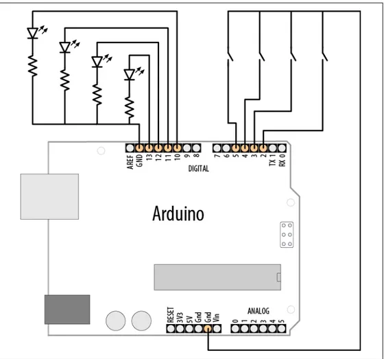
This sketch creates two arrays: an array of integers for pins connected to switches and an array of pins connected to LEDs, as shown in Figure 2-1:
/*
array sketch
an array of switches controls an array of LEDs see Chapter 5 for more on using switches see Chapter 7 for information on LEDs */
int inputPins[] = {2,3,4,5}; // create an array of pins for switch inputs int ledPins[] = {10,11,12,13}; // create array of output pins for LEDs void setup()
{
for(int index = 0; index < 4; index++) {
pinMode(ledPins[index], OUTPUT); // declare LED as output pinMode(inputPins[index], INPUT); // declare pushbutton as input digitalWrite(inputPins[index],HIGH); // enable pull-up resistors
//(see Recipe 5.2) }
}
void loop(){
for(int index = 0; index < 4; index++) {
int val = digitalRead(inputPins[i]); // read input value
if (val == LOW) // check if the switch is pressed {
digitalWrite(ledPins[index], HIGH); // turn LED on if switch is pressed }
else {
digitalWrite(ledPins[i], LOW); // turn LED off }
} }
Discussion
Arrays are collections of consecutive variables of the same type. Each variable in the collection is called an element. The number of elements is called the dimension of the array.
The preceding example demonstrates a common use of arrays in Arduino code: storing a collection of pins. Here the pins connect to switches and LEDs (a topic covered in more detail in Chapter 5). The important parts of this example are the declaration of the array and access to the array elements.
The following line of code declares (creates) an array of integers with four elements and initializes each element. The first element is set equal to 2, the second to 3, and so on:
int inputPins[] = {2,3,4,5};
If you don’t need to initialize the values when you declare an array (perhaps the values will only be available when the sketch is running) you can declare the array as follows:
int array[4];
This declares an array of four elements with the initial value of each element set to zero. The number within the square brackets ([]) is the dimension, and this sets the number of elements. This array has a dimension of four and can hold, at most, four integer values. The dimension can be omitted if array declaration contains initializers (as shown in the first example) because the compiler figures out how big to make the array by counting the number of initializers.
The first element of the array is element[0]:
int firstElement = inputPin[0]; // this is the first element
The last element is one less than the dimension, so in the preceding example, with a dimension of four, the last element is element 3:
Int lastElement = inputPin[3]; // this is the last element
It may seem odd that an array with a dimension of four has the last element accessed using array[3], but because the first element is array[0], the four elements are:
array[0],array[1],array[2],array[3]
In the previous sketch, the four elements are accessed using a for loop:
for(int index = 0; index < 4; index++) {
//get the pin number by accessing each element in the pin arrays pinMode(ledPins[index], OUTPUT); // declare LED as output pinMode(inputPins[index], INPUT); // declare pushbutton as input }
This loop will step through the variable index with values starting at 0 and ending at 3. It is a common mistake to accidentally access an element that is beyond the actual dimension of the array. This is a bug that can have many different symptoms and care must be taken to avoid it. One way to keep your loops under control is to set the dimension of an array by using a constant as follows:
const int PIN_COUNT = 4; // define a constant for the number of elements int inputPins[PIN_COUNT] = {2,3,4,5};
for(int index = 0; index < PIN_COUNT; index++) pinMode(inputPins[index], INPUT);
The compiler will not report an error if you accidentally try to store or read beyond the size of the array. You must be careful that you only access elements that are within the bounds you have set. Using a con-stant to set the dimension of an array and in code referring to its elements helps your code stay within the bounds of the array.
Another common use of arrays is to hold a string of text characters. In Arduino code, these are called character strings (strings for short). A character string consists of one or more characters, followed by the null character (the value 0) to indicate the end of the string.
The null at the end of a character string is not the same as the character 0. The null has an ASCII value of 0, whereas 0 has an ASCII value of 48.
Methods to use strings are covered in Recipes 2.5 and 2.6.
See Also
Recipe 5.2; Recipe 7.1
2.5 Using Arduino String Functionality
Problem
You want to manipulate text. You need to copy it, add bits together, and determine the number of characters.
Solution
Recipe 2.4 describes Arduino arrays in general. Text is stored in arrays of characters. They are usually called strings. Arduino has an added capability for using an array of characters called String that can store and manipulate text strings.
The word String with an uppercase S refers to the Arduino text capability provided by the Arduino String library. The word string with a lowercase s refers to the group of characters rather than the Arduino String functionality.
This recipe demonstrates how to use Arduino strings.
The String capability was introduced in version 19 of Arduino. If you are using an older version, you can use the TextString library; see the link at the end of this recipe.
Load the following sketch onto your board, and open the Serial Monitor to view the results:
/*
Basic_Strings sketch */
String text1 = "This string"; String text2 = " has more text";
String text3; // to be assigned within the sketch void setup() { Serial.begin(9600); Serial.print( text1); Serial.print(" is "); Serial.print(text1.length()); Serial.println(" characters long."); Serial.print("text2 is ");
Serial.print(text2.length()); Serial.println(" characters long."); text1.concat(text2);
Serial.println("text1 now contains: "); Serial.println(text1); } void loop() { }
Discussion
This sketch creates two variables of type String, called message and anotherMessage. Variables of type String have built-in capabilities for manipulating text. The statement message.length() returns (provides the value of) the length (number of characters) in the string message.
message.concat(anotherMessage) combines the contents of strings; in this case, it ap-pends the contents of anotherMessage to the end of message (concat is short for concatenate).
The Serial Monitor will display the following:
This string is 11 characters long. text2 is 14 characters long. text1 now contains:
This string has more text
Another way to combine strings is to use the string addition operator. Add these two lines to the end of the setup code:
text3 = text1 + " and more"; Serial.println(text3);
The new code will result in the Serial Monitor adding the following line to the end of the display:
This is a string with more text and more
You can use the indexOf and lastIndexOf functions to find an instance of a particular character in a string.
Because the String class is a new addition to Arduino, you will come across a lot of code that uses arrays of characters rather than the String type. See Recipe 2.6 for more on using arrays of characters with-out the help of the Arduino String functionality.
If you see a line such as the following:
char oldString[] = "this is a character array";
the code is using C-style character arrays (see Recipe 2.6). If the declaration looks like this:
String newString = "this is a string object";
the code uses Arduino Strings. To convert a C-style character array to an Arduino String, just assign the contents of the array to the String object:
char oldString[] = "I want this character array in a String object"; String newsString = oldString;
See Also
The Arduino distribution provides String example sketches.
Tutorials for the new String library are available at http://arduino.cc/en/Tutorial/Home Page, and a tutorial for the original String library is available at http://www.arduino.cc/ en/Tutorial/TextString.
2.6 Using C Character Strings
Problem
You want to understand how to use raw character strings: you want to know how to create a string, find its length, and compare, copy, or append strings. The C language does not support the Arduino-style String capability, so you want to understand code written to operate with primitive character arrays.
Solution
Arrays of characters are sometimes called character strings (or simply strings for short).
Recipe 2.5 describes Arduino arrays in general. This recipe describes functions that operate on character strings.
You declare strings like this:
char StringA[8]; // declare a string of up to 7 chars plus terminating null char StringB[8] = "Arduino"; // as above and init(ialize) the string to "Arduino";
char StringC[16] = "Arduino"; // as above, but string has room to grow char StringD[ ] = "Arduino"; // the compiler inits the string and calculates size
Use strlen (short for string length) to determine the number of characters before the null:
int length = strlen(string); // return the number of characters in the string
length will be 0 for StringA and 7 for the other strings shown in the preceding code. The null that indicates the end of the string is not counted by strlen.
Use strcpy (short for string copy) to copy one string to another:
strcpy(destination, source); // copy string source to destination
Use strncpy to limit the number of characters to copy (useful to prevent writing more characters than the destination string can hold). You can see this used in Recipe 2.7:
strncpy(destination, source, 6); // copy up to 6 characters from source to destination
Use strcat (short for string concatenate) to append one string to the end of another:
strcat(destination, source); // append source string to the end of the destination string
Always make sure there is enough room in the destination when copying or concatenating strings. Don’t forget to allow room for the terminating null.
Use strcmp (short for string compare) to compare two strings. You can see this used in
Recipe 2.7:
if(strcmp(str, "Arduino") == 0)
// do something if the variable str is equal to "Arduino"
Discussion
Text is represented in the Arduino environment using an array of characters called strings. A string consists of a number of characters followed by a null (the value 0). The null is not displayed, but it is needed to indicate the end of the string to the software.
See Also
See one of the many online C/C++ reference pages, such as http://www.cplusplus.com/ reference/clibrary/cstring/ and http://www.cppreference.com/wiki/string/c/start.
2.7 Splitting Comma-Separated Text into Groups
Problem
You have a string that contains two or more pieces of data separated by commas (or any other separator). You want to split the string so that you can use each individual part.
Solution
This sketch prints the text found between each comma:
/*
* SplitSplit sketch
* split a comma-separated string */
String message= "Peter,Paul,Mary"; // an example string
int commaPosition; // the position of the next comma in the string void setup() { Serial.begin(9600); } void loop() {
Serial.println(message); // show the source string do { commaPosition = message.indexOf(','); if(commaPosition != -1) { Serial.println( message.substring(0,commaPosition));
message = message.substring(commaPosition+1, message.length()); }
else
{ // here after the last comma is found if(message.length() > 0)
Serial.println(message); // if there is text after the last comma, print it } } while(commaPosition >=0); delay(5000); }
The Serial Monitor will display the following:
Peter,Paul,Mary Peter
Paul
Discussion
This sketch uses String functions to extract text from between commas. The following code:
commaPosition = message.indexOf(',');
sets the variable commaPosition with the position of the first comma in the String named message (it will be set to -1 if no comma is found). If there is a comma, the substring function is used to print the text from the beginning of the string to the position of the comma. The text that was printed is removed from message in this line:
message = message.substring(commaPosition+1, message.length());
substring returns a string starting from commaPosition+1 (the position just after the first comma) up to the length of the message. This results in that message containing only the text following the first comma. This is repeated until no more commas are found (commaIndex will be equal to -1).
If you are an experienced programmer, you can also use the low-level functions that are part of the standard C library. The following sketch has similar functionality to the preceding one using Arduino strings:
/*
* SplitSplit sketch
* split a comma-separated string */
const int MAX_STRING_LEN = 20; // set this to the largest string you'll process char stringList[] = "Peter,Paul,Mary"; // an example string
char stringBuffer[MAX_STRING_LEN+1]; // a static buffer for computation and output void setup() { Serial.begin(9600); } void loop() { char *str; char *p;
strncpy(stringBuffer, stringList, MAX_STRING_LEN); // copy source string Serial.println(stringBuffer); // show the source string for( str = strtok_r(stringBuffer, ",", &p); // split using comma
str; // loop while str is not null str = strtok_r(NULL, ",", &p) // get subsequent tokens )
{ Serial.println(str); if(strcmp(str, "Paul") == 0) Serial.println("found Paul"); } delay(5000); }
The core functionality comes from the function named strtok_r (the name of the ver-sion of strtok that comes with the Arduino compiler). The first time you call strtok_r you pass it the string you want to tokenize (separate into individual values). But strtok_r overwrites the characters in this string each time it finds a new token, so it’s best to pass a copy of the string as shown in this example. Each call that follows uses a NULL to tell the function that it should move on to the next token. In this example, each token is printed to the serial port and also compared to a target string ("Paul"). If your tokens consist only of numbers, see Recipe 4.5. This shows how to extract numeric values separated by commas in a stream of serial characters.
See Also
Recipe 2.5; online references to the C/C++ functions strtok_r and strcmp
2.8 Converting a Number to a String
Problem
You need to convert a number to a string, perhaps to show the number on an LCD or other display.
Solution
The String variable will convert numbers to strings of characters automatically. You can use literal values, or the contents of a variable. For example, the following code will work:
String myNumber = 1234;
As will this:
int value = 127
String myReadout = "The reading was "; myReadout.concat(value);
Or this:
int value = 127;
String myReadout = "The reading was "; myReadout += value;
Discussion
If you are converting a number to display as text on an LCD or serial device, the simplest solution is to use the conversion capability built into the LCD and Serial libraries (see
Recipe 4.2). But perhaps you are using a device that does not have this built-in support (see Chapter 13) or you want to manipulate the number as a string in your sketch. The Arduino String class automatically converts numerical values when they are as-signed to a String variable. You can combine (concatenate) numeric values at the end of a string using the concat function or the string + operator.
The + operator is used with number types as well as strings, but it be-haves differently with each.
The following code results in number having a value of 13:
int number = 12; number += 1;
With a String, as shown here:
String textNumber = 12 textNumber += 1;
textNumber is the text string "121".
Prior to the introduction of the String class, it was common to find Arduino code using the itoa or ltoa function. The names come from “integer to ASCII” (itoa) and “long to ASCII” (ltoa). The String version described earlier is easier to use, but the following will help if you want to understand code that uses itoa or ltoa.
These functions take three parameters: the value to convert, the buffer that will hold the output string, and the number base (10 for a decimal number, 16 for hex, and 2 for binary).
The following sketch illustrates how to convert numeric values using ltoa:
/*
* NumberToString
* Creates a string from a given number */
void setup() {
Serial.begin(9600); }
char buffer[12]; // long data type has 11 characters (including the // minus sign) and a terminating null
void loop() { long value = 12345; ltoa(value, buffer, 10); Serial.print( value); Serial.print(" has "); Serial.print(strlen(buffer)); Serial.println(" digits"); value = 123456789; ltoa(value, buffer, 10); Serial.print( value); Serial.print(" has "); Serial.print(strlen(buffer)); Serial.println(" digits"); delay(1000); }
Your buffer must be large enough to hold the maximum number of characters in the string. For 16-bit integers, that is seven characters (five digits, a possible minus sign, and a terminating 0 that always signifies the end of a string); 32-bit long integers need 12 character buffers (10 digits, the minus sign, and the terminating 0). No warning is given if you exceed the buffer size; this is a bug that can cause all kinds of strange symptoms, because the overflow will corrupt some other part of memory that may be used by your program. The easiest way to handle this is to always use a 12-character buffer and always use ltoa because this will work on both 16-bit and 32-bit values.
2.9 Converting a String to a Number
Problem
You need to convert a string to a number. Perhaps you have received a value as a string over a communication link and you need to use this as an integer or floating-point value.
Solution
There are a number of ways to solve this. If the string is received as serial data, it can be converted on the fly as each character is received. See Recipe 4.3 for an example of how to do this using the serial port.
Another approach to converting text strings representing numbers is to use the C lan-guage conversion function called atoi (for int variables) or atol (for long variables). This code fragment terminates the incoming digits on any character that is not a digit (or if the buffer is full):
int blinkRate; // blink rate stored in this variable
char strValue[6]; // must be big enough to hold all the digits and the // 0 that terminates the string
void loop() {
if( Serial.available()) {
char ch = Serial.read();
if(index < 5 && ch >= '0' && ch <= '9'){
strValue[index++] = ch; // add the ASCII character to the string; }
else {
// here when buffer full or on the first non digit
strValue[index] = 0; // terminate the string with a 0
blinkRate = atoi(strValue); // use atoi to convert the string to an int index = 0; } } blink(); }
Discussion
The obscurely named atoi (for ASCII to int) and atol (for ASCII to long) functions convert a string into integers or long integers. To use them, you have to receive and store the entire string in a character array before you can call the conversion function. The code creates a character array named strValue that can hold up to five digits (it’s declared as char strValue[6] because there must be room for the terminating null). It fills this array with digits from Serial.read until it gets the first character that is not a valid digit. The array is terminated with a null and the atoi function is called to convert the character array into the variable blinkRate.
A function called blink is called that uses the value stored in blinkRate. The blink function is shown in Recipe 4.3.
As mentioned in the warning in Recipe 2.4, you must be careful not to exceed the bound of the array. If you are not sure how to do that, read through Recipe 2.13.
This example builds a character array, rather than using the String class. At the time of this writing, the Arduino String library did not have the functionality to convert a string of numbers into a numeric value.
See Also
See one of the many online C/C++ reference pages, such as http://www.cplusplus.com/ reference/clibrary/cstdlib/atoi/ or http://www.cppreference.com/wiki/string/c/atoi.