1
UNIVERSITÀ DI PISA
FACOLTÀ DI INGEGNERIA
Corso di Laurea Magistrale in
Ingegneria Biomedica
Tesi di Laurea
Optical filter simulating foveated vision:
modeling and preliminary experiments
Relatori:
Prof. D. De Rossi
Ing. F. Carpi
Candidata:
Eleonora Cipolli
A.A. 2012/2013
2
Alla mia famiglia che mi ha
sostenuta in ogni aspetto fin qui.
A Ramy che mi ha pazientemente
aspettata in questo lungo
3
Table of contents
1 INTRODUCTION ... 5
2 THE HUMAN EYE AND THE VISUAL PERCEPTION ... 7
Introduction ... 7
2.1 Anatomy of the eye ... 8
2.2 The retina ... 11
2.2.1 Structure of the retina ... 12
2.2.2 Blood supply to the retina ... 14
2.2.3 Fovea structure ... 15
2.2.4 Macula lutea ... 17
2.2.5 Ganglion cell fiber layer ... 17
2.2.6 Photoreceptors ... 18
2.2.7 Optic nerve ... 20
2.3 A review of artificial vision ... 21
2.3.1Physical approaches ... 21 2.3.2 Computable methods ... 23 References ... 26 3 LIGHT SCATTERING ... 28 3.1 Introduction to light ... 28 3.2 Maxwell’s Equations ... 31
3. 3 Particle theory of light ... 33
3.4 Quantum theory ... 35
3.5 Wave propagation ... 36
3. 6 Interaction of electromagnetic radiation and matter ... 39
3.7 Scattering ... 41 3.7.1 Light scattering ... 44 3.7.2 Types of scattering ... 45 3.7.3 Rayleigh scattering ... 45 3.7.4 Mie scattering ... 47 3.7.5 Brillouin scattering ... 47 3.7.6 Raman scattering ... 47 3.8 Scattering by particles ... 48
4
3.8.1 Angle- dependent scattering ... 53
References ... 58
4 TUNEABLE OPTICAL FILTER: PROPOSED EVALUATION SYSTEM ... 59
4.1 System description ... 60 4.2 Electroactive membrane ... 63 4.3 Filters ... 66 4.4 Frames ... 67 4.5 Housing ... 67 4.6 Camera ... 69 4.7 Optotune Lens ... 69 References: ... 71
5 SIMULATION: CST STUDIO SUITE® AND COMSOL MULTIPHYSICS® ... 73
5.1 CST STUDIO SUITE ® ... 73
5.1.1 Develop a simulation with CST STUDIO SUITE® ... 74
5.2 Comsol Multiphysics ® ... 78
5.2.1 Develop a simulation with Comsol Multiphysics® ... 79
6 PROTOTYPING: METHODS AND MATERIALS ... 81
6.1 Filter ... 81
6.2 Filter characterization ... 88
6.3 Resolution measurement in Matlab ... 90
References: ... 91
7 RESULTS AND DISCUSSION ... 92
7.1 Comsol Multiphysics ® results ... 92
7.2 CST STUDIO SUITE® results ... 96
7.3 Experimental evaluation: resolution measurement in Matlab ... 104
7.4 Discussion of results ... 107
8 CONCLUSION AND FUTURE WORK ... 109
5
Chapter 1
INTRODUCTION
This thesis is a preliminary work to design an electrically tuneable optical filter based on light scattering (within the visible spectrum of wavelengths 400 - 700 nm) in order to mimic the foveal vision in human eyes.
The human vision system is highly dependent on the spatial frequency in sampling, coding, processing and understanding of how physical due to non-uniformity in the distribution of photoreceptors and neural cells on the retina.
The photoreceptors distribution of human retina is eccentricity- dependent (eccentricity is defined as the distance between a photoreceptor and the centre of the polar structure). The small region, called fovea, has the greatest density of cones (they provide the eye’s colour sensitivity and are active at high light levels, i.e. photopic vision) and such distribution decreases toward the periphery. The rods density distribution is the opposite (they are responsible for vision at very low light levels, i.e. scotopic vision). See fig.1.
For this reason, the spatial resolution is not constant across our field of view, but is maximal at the fovea. Thanks to the eye movement objects placed in all areas of the space can be perceived with sharpness. Indeed, the image perceived in our mind is always much sharper in a neighborhood of the
6 gaze point and appears blurred in the surrounding area. For the physical and photochemical features of rods and cones, the human vision acuity is high (about 60 cyc/ º ) in the fovea. Such a value is about 10 times lower in the periphery.
Several devices or computational solutions have been proposed for mimicking such effect. For instance Sandini [1] proposed a silicon retina-like sensor characterized by a spatial-variant resolution. They used a CMOS technology with a log-polar distribution of sensor size.
Other approaches reproduce the foveated vision (FV) using traditional CCD or CMOS sensors with uniform pixel dimension and applying algorithms through digital filtering, to reduce the effective resolution in the peripheral part of the image.
On one hand the silicon retinal-like sensor is task-specific and the spatial-variant resolution is fixed when designed, on the other hand digital filtering increases the computational load of the processing system and does not take into account to the aliasing problem. In other words sampling targets with unknown spatial frequency could lead to erroneous data interpretation.
Differently we are looking for a tuneable optical response upon an electrical stimulation so as to achieve an eccentricity-dependent resolution.
Our work is aimed at developing an optical filter that can be coupled to common CCD or CMOS sensors. This should be at the same time tuneable, upon an electrically stimulus, and attenuate spatial frequencies before the photodetector sampling. Our approach is based on the phenomenon of light scattering to filter the input light signal. We used nano-particles, selected based on size and optical properties, to create diffusion of light and thus reduce the optical resolution of an image (captured by a camera- sensor ).The filter should show a spatial variant distribution of the nano-particles, higher in pheriphery and lower in the centre.
During next chapters the work performer during this thesis is shown. It can be summarized as follow: - Selection of particles, in terms of sizes and optical properties, based on visible light wavelength. - Simulation of scattering implemented by the filter (CST STUDIO SUITE® and Comsol
Multiphysics)
- Filter realization where different methods had been tested. This phase concluded with the use of a flexible substrate to encapsulate nano-particles. The filter obtained has a constant volumetric density of particles in Sylgard184® which can be deformed during the activation phase of the electroactive membrane.
- Resolution measurement in order to evaluate the scattering performed by the filter (in Matlab, with “sfrmat3” code).
References:
[1] "A retina-like CMOS sensor and its applications." Sandini, Giulio, et al. Sensor Array and Multichannel Signal Processing Workshop. 2000. Proceedings of the 2000 IEEE. IEEE, 2000
7
Chapter
2
THE HUMAN EYE AND THE VISUAL PERCEPTION
In this chapter we give a brief description of the human visual system describing the anatomy and physiology of the main structures of the human eye. We will discuss how the human eye is done, mainly by dwelling on the retina and its photoreceptors, the light-sensitive cells which are responsible for detecting light and, therefore, enable us to see. The transduction (conversion) of light into nerve signals that the brain can understand takes place in these specialized cells. They allow us to turn a scanned image from the optical components of the eye ( cornea and lens ) into an electrical signal and then convert it back to image inside our brain.
In addition to natural vision , we will present some approaches currently in use that try to mimic the foveal vision. These techniques can be classified into computationals and physicals ones. We will present the solutions proposed in literature pointing out the pros and cons of each, thus offering our work as a additional alternative to bio- engineering systems proposed so far .
Introduction
The human eye is an amazingly complex structure that enables sight, one of the most important of the human senses. Sight underlies our ability to understand the world around us and to navigate within our environment. As we look at the world around us, our eyes are constantly taking in light, a component fundamental to the visual process. The front of the human eye contains a curved lens, through which light refl ected from objects in the surrounding environment passes. The light travels deep into the eyeball, passing all the way to the back of the eye, where it converges to a point. A unique set of cells at the back of the eye receives the light, harnessing its energy by converting it into an electrical impulse, or signal, that then travels along neurons in the brain. The impulses are carried along a neuronal pathway that extends from the back of the eye all the way to the back of the brain, ultimately terminating in a region known as the visual cortex. There, the electrical signals from both eyes are processed and unified into a single image. The amount of time between the moment when light enters the eye and when a unified image is generated in the brain is near instantaneous, taking only fractions of a second.[1]
8
2.1 Anatomy of the eye
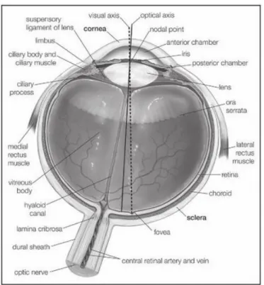
The overall shape of the eye is nearly spherical: its frontal part, the cornea, protrudes on the remaining surface of the eye. The three diameters of the eyeball are therefore different: the transverse diameter is 23.5 mm, the vertical diameter is 23 mm, the anterior to posterior diameter is approximately 26 mm. The weight of the eye is around 7 grams and its remarkable consistency is due to the fluid pressure (15 mm / Hg) contained in the cavity of the eyeball.
The wall of the eye consists of three concentric layers: the fibrous layer, the vascular layer and the nervous layer. The outermost layer is a fibrous sheet comprising the cornea and the sclera.
The cornea, dome-shaped transparent membrane of about 12 mm in diameter convex front and rear with radii of curvature, respectively, of 7.7 mm and 6.9 mm, [2].The cornea has five layers, which together give a a thickness of 0.5–0.6 mm in the center and 0.6–0.8 mm at the periphery. Except at its margins, the cornea has no blood vessels: it receives nutrients via diffusion from the tear fluid through the outside surface and the aqueous humour. On the other side it contains many nerves and is very
Fig. 1: Horizontal cross section of the human eye, showing the structures of the eye. Encyclopaedia Britannica,
9 sensitive to pain or touch. It protects the pupil, the iris, and the inside of the eye from penetration by foreign bodies and it is the first and most powerful element in the eye’s focusing system. As light passes through the cornea, it is partially refracted before reaching the lens [3]. The cornea has a refractive index equal to 1.376 and determines most of the refractive power of the eye (approximately 43 dioptres) even if it contributes in a static manner.
The sclera, known as the "white of the eye", forms the supporting wall of the eyeball offering
resistance to internal and external forces thanks to the vitreous humor. It is essentially continuous with the clear cornea: the collagen fibers of the sclera are an extension of cornea fibers.
The intermediate layer, called vascular tunic or uvea coat, is a vascular layer which consists of the iris, the choroid, and the ciliary body.
The iris is the pigmented muscular curtain near the front of the eye, between the cornea and the lens, that is perforated by an opening called the pupil. The iris consists of two sheets of smooth muscle with contrary actions: dilation (expansion) and contraction (constriction). These muscles control the size of the pupil and thus determine how much light reaches the sensory tissue of the retina. The sphincter muscle of the iris is a circular muscle that constricts the pupil in bright light, whereas the dilator muscle of the iris expands the opening when it contracts. [4]The amount of pigment contained in the iris determines eye colour.
The average size of the pupil is 3-4 mm : at its maximum contraction, it may be less than 1 mm in diameter, and it may increase up to 10 times to its maximum diameter. [5]
The choroid, also known as the choroidea or choroid coat, is the vascular layer of the eye, containing connective tissue, and lying between the retina and the sclera.
The ciliary body is the circumferential tissue inside the eye composed of the ciliary muscle and ciliary processes [6]It is located behind the iris and before wing choroid. It is triangular in horizontal section and is coated by a double layer, the ciliary epithelium.
The ciliary body has three functions: accommodation, aqueous humor production and the production, and maintenance of the lens zonules. It also anchors the lens in place. Accommodation essentially means that when the ciliary muscle contracts, the lens becomes more convex, generally improving the focus for closer objects. When it relaxes it flattens the lens, generally improving the focus for farther objects. One of the essential roles of the ciliary body is also the production of the aqueous humor, which is responsible for providing most of the nutrients for the lens and the cornea and involved in waste management of these areas.
The retina is a light-sensitive layer of tissue, at the back of the eye that covers about 65% of its interior surface. The optics of the eye create an image of the visual world on the retina (through the cornea and lens) , which serves much the same function as the film in a camera. Light striking the retina initiates a cascade of chemical and electrical events that ultimately trigger nerve impulses. These are sent to various visual centres of the brain through the fibres of the optic nerve.
10 The eye can also be divided into two segments, the front and rear. The anterior segment is formed by the front chamber and the rear which are separated by the iris. Both rooms are filled by 'aqueous humor, which is a liquid similar to blood plasma actively secreted by the ciliary processes. Its role is to provide nourishment for the lens and the cornea, to dispose of waste products and to maintain the shape of the anterior portion of the eye.
The balance between aqueous humor secretion and reabsorption is important to maintain proper intraocular pressure.
The posterior segment contains instead the vitreous body or vitreous humor which is a colorless and transparent gelatinous substance that allows the passage of light and also has support function to keep the shape of the bulb. The two segments are separated by the crystalline lens.
The crystalline lens is a nearly transparent biconvex structure suspended behind the iris of the eye. Along with the cornea helps to refract light to be focused on the retina.
The lens is made up of unusual elongated cells that have no blood supply but obtain nutrients from the surrounding fluids, mainly the aqueous humour that bathes the front of the lens. The shape of the lens can be altered by the relaxation and contraction of the ciliary muscles surrounding it, thus enabling the eye to focus clearly on objects at widely varying distances. The ability of the lens to adjust from a distant to a near focus, called accommodation, gradually declines with age.[7]
When the ciliary muscles are relaxed, the tension exerted by the suspensory ligaments tends to flatten the lens; resting its front surface has a radius of curvature of 10.6 mm and the rear of -6 mm[8]. When the ciliary muscles contract, it reduces the tension of the suspensory ligaments and,
consequently, the lens tends to assume a spheroidal form by virtue of its elastic properties. In the state of complete accommodation (maximum contraction of the ciliary muscles) the front and rear surfaces of the lens have a curvature respectively of 6 mm and -5.5 mm [9].
In this state, the dioptric power is maximum and a normal eye can put focus at distances of 25-30 cm (near point)[10].
11 Cornea, aqueous humor, crystalline lens and vitreous body constitute the dioptric means (or dioptric system or apparatus) of the eye, which can be considered as a converging lens with a significant refractive power: about 60 diopters.
2.2 The retina
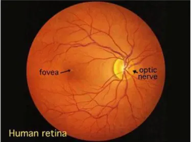
The retina is a light-sensitive layer of tissue, lining the inner surface of the eye. When an
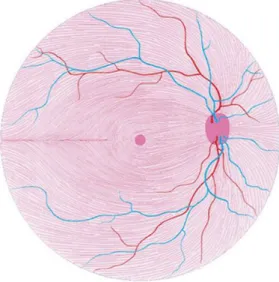
ophthalmologist uses an ophthalmoscope to look into your eye he sees the following view of the retina (Fig. 3).
Fig. 2: Unaccommodated crystalline lens (A) and accommodate crystalline lens (B).
Fig. 3: A view of the retina seen though an ophthalmoscope.
12 In the retina, there are three sections: anterior (retina or iris), average (retina or ciliary) and rear (or part of the retina or optic retina only). The anterior and middle portions are not able to perceive visual stimuli, while the rear portion is fully developed and functionally efficient.
The optic disc, a part of the retina sometimes called "the blind spot" because it lacks photoreceptors, is located at the optic papilla, a nasal zone where the optic-nerve fibers leave the eye. It appears as an oval white area of 3mm. Most of the vessels of the retina radiate from the center of the optic nerve. In general, the retina is similar to a circular disc of diameter between 30 and 40 mm and a thickness of approximately 0.5 mm. The retina is the back part of the eye that contains the cells that respond to light. These specialized cells are called photoreceptors.
2.2.1 Structure of the retina
The retina has a complex structure. The microscope discerns 10 layers in the retina – counted from inside -out. The main layers are pigment epithelium and light-sensitive cells (photoreceptor layer). These are followed by external limiting membrane, outer nuclear layer, outer plexiform (synaptic) layer, inner nuclear layer, inner plaxiform layer, ganglion cell layer, nerve fiber layer, inner limiting membrane.
1) The Pigment Epithelium Layer
The pigment epithelium layer is the outermost layer of the retina consisting of pigmented cuboidal cells that contain melanin. The bases of these cuboidal cells are firmly attached to the choroidal layer of the eye located outside the retina. The presence of tight junctions between these cuboidal cells prevents the flow of ions and plasma. The cuboidal cells have microvilli at their apical regions, which interdigitate with photoreceptors. The pigmented epithelium cells provide nutrition (glucose and essential ions) to photoreceptors and other cells associated with them. The black pigment, melanin, absorbs any light that is not captured by the retina and prevents it from reflecting back to the retina,
Fig.4: Some layers of the retina
13 which would otherwise result in the degradation of the image. Thus, the pigment epithelium layer protects the photoreceptors from damaging levels of light.
The pigmented epithelium layer develops from the outer aspect of the optic cup as a component of the choroidal layer. The rest of the retina develops from the inner aspect of the optic cup, which folds inwards and becomes apposed to the pigmented epithelium. A potential space persists between the pigmented epithelium and rest of the retina. This anatomic arrangement renders the contact between the pigmented epithelium layer and the neural retina (photoreceptors and other cells associated with the sensing and processing of light stimulus) mechanically unstable. Therefore, the pigment epithelium layer sometimes detaches from the neural retina. In this condition, known as retinal detachment, the photoreceptors can be damaged because they may not receive the nutrition that is normally provided by the pigment epithelium layer. Retinal detachment is now repaired by laser surgery.
2) The Layer of Rods and Cones
Rods and cones are known as photoreceptors. The structure and function of photoreceptors are described later. The light-sensitive portions of these photoreceptors are contained in the layer of rods and cones.
Rods contain a photosensitive substance visual purple (rhodopsin) and subserve the peripheral vision and vision of low illumination (scotopic vision). Cones also contain a photosensitive substance and are primarily responsible for highly discriminatory central vision (photopic vision) and colour vision. In most regions of the retina, the rods outnumber the cones (there are approximately 100 million rods and 5 million cones in the human retina). One exception to this rule is the region of greatest visual acuity, the fovea (a depression in the center of the macula). The fovea contains only cones. High visual acuity at the fovea, especially in the foveola, is attributed to the presence of an extremely high density of cone receptors in this region of the retina. Other anatomical features that contribute to high visual acuity at the fovea are diversion of blood vessels away from the fovea and displacement of layers of cell bodies and their processes around the fovea. These anatomical features allow minimal scattering of light rays before they strike the photoreceptors. Disorders affecting the function of fovea, which, as mentioned earlier, is a restricted region of the retina (1.2–1.4 mm in diameter), cause dramatic loss of vision.
3) The External Limiting Membrane
The photosensitive processes of rods and cones pass through the external limiting membrane, which is a fenestrated membrane, in order to be connected with their cell bodies. This region also contains processes of Müller cells (these cells are homologous to the glial cells of the central nervous system [CNS] and are unique to the retina).
4) The Outer Nuclear Layer
14 5) The Outer Plexiform Layer
The outer plexiform layer contains the axonal processes of rods and cones, processes of horizontal cells, and dendrites of bipolar cells. This is one of the layers where synaptic interaction between photoreceptors and horizontal and bipolar cells takes place.
6) The Inner Nuclear Layer
The inner nucleus layer contains the cell bodies of amacrine cells, horizontal cells, and bipolar cells. Amacrine and horizontal cells, or association cells, function as interneurons. Amacrine cells are interposed between the bipolar and ganglion cells and serve as modulators of the activity of ganglion cells. The role of horizontal and bipolar cells in the processing of signals from the photoreceptors is discussed later.
7) The Inner Plexiform Layer
The inner plexiform layer contains the connections between the axons of ganglion cells and processes of amacrine cells of the inner nuclear layer. This is another layer where synaptic interaction between different retinal cells takes place.
8) The Layer of Ganglion Cells
The cell bodies of multipolar ganglion cells are located in the layer of ganglion cells. The fovea centralis of the retina has the greatest density of ganglion cells. The final output from the retina after visual stimulation is transmitted to the CNS by the ganglion cells via their axons in the optic nerve. The ganglion cells are the only retinal cells that are capable of firing action potentials.
9) Nerve fiber layer (stratum opticum)
Consists of axons of the ganglion cells, which pass through the lamina cribrosa to form the optic nerve.
10) Internal limiting membrane.
It is the innermost layer and separates the retina from vitreous. It is formed by the union of terminal expansions of the Muller’s fibers, and is essentially a basement membrane.
2.2.2 Blood supply to the retina
There are two sources of blood supply to the mammalian retina: the central retinal artery and the choroidal blood vessels. The choroid receives the greatest blood flow (65-85%) [11] and is vital for the maintenance of the outer retina (particularly the photoreceptors) and the remaining 20-30% flows
15 to the retina through the central retinal artery from the optic nerve head to nourish the inner retinal layers. The central retinal artery has 4 main branches in the human retina.
2.2.3 Fovea structure
The fovea is a small portion of the retina, where there is the highest visual acuity .at the centre it forms a small depression, called the foveal pit [12] . Radial sections of this small circular region of retina measuring less than a quarter of a millimeter (200 microns) .
It is an area where the cones are concentrated at the maximum density and arranged with the most efficient packing geometry which is in a hexagonal mosaic. Starting at the outskirts of the fovea, however, rods gradually appear, and the absolute density of cone receptors progressively decreases.
In the primate fovea (including humans) the ratio of ganglion cells to photoreceptors is about 2.5; almost every ganglion cell receives data from a single cone, and each cone feeds onto between 1 and 3 ganglion cells.[13] . Therefore, the acuity of foveal vision is limited only by the density of the cone mosaic, and the fovea is the area of the eye with the highest sensitivity to fine details [14].
Cones in the central fovea express pigments that are sensitive to green and red light. These cones are the 'midget' pathways that also underpin high acuity functions of the fovea.
The fovea comprises less than 1% of retinal size but takes up over 50% of the visual cortex in the brain.[15] In the fovea there are neither cones S nor the rods; without cones S are avoided phenomena of chromatic aberration in the area of maximum visual acuity.
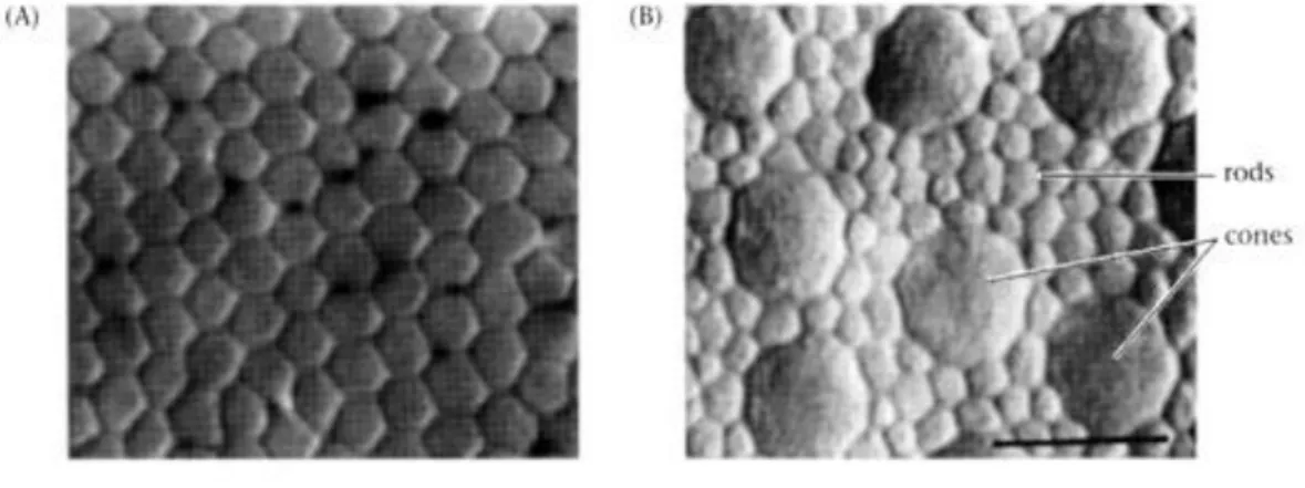
Fig. 5: The spatial mosaic f the human cones.
Cross sections of the human retina at the level of the inner segment showing (A) cones in the fovea and (B) cones in the periphery.
16
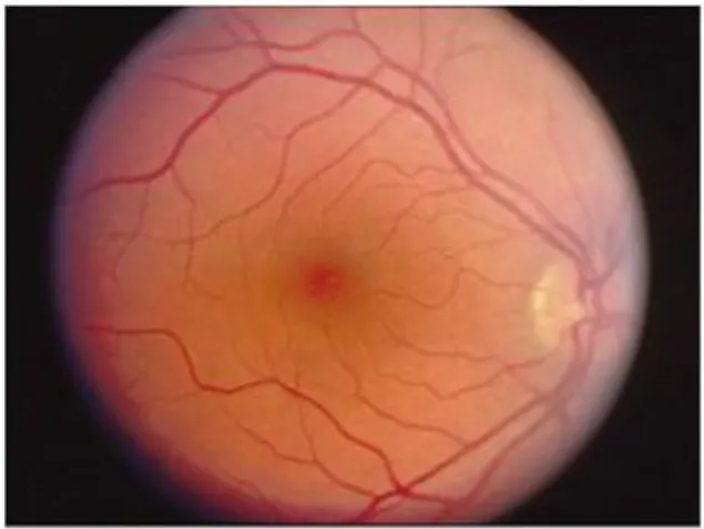
Fig. 7: (A) fundus photo of a normal human macula, optic nerve and blood vessels around the fovea. B) Optical coherence tomography (OCT) images of the same normal macular in the area that
is boxed in green above (A). The foveal pit (arrow) and the sloping foveal walls with dispelled inner retina neurons (green and red cells) are clearly seen. Blue cells are the packed photoreceptors,
primarily cones, above the foveal center (pit).
Fig. 6: Vertical section of the human fovea from Yamada (1969).
Os,outer segment; is,inner segment; OLM, outer limiting membrane; ONL, outer nuclear layer; H, henler filbers; INL, inner nuclear layer; ILM, inner limiting membrane; G, ganglion cells.
17
2.2.4 Macula lutea
The whole foveal area including foveal pit, foveal slope, parafovea and perifovea is considered the macula of the human eye. Familiar to ophthalmologists is a yellow pigmentation to the macular area known as the macula lutea (Fig. 7).
This pigmentation is the reflection from yellow screening pigments, the xanthophyll carotenoids zeaxanthin and lutein[16] present in the cone axons of the Henle fibre layer. The macula lutea is thought to act as a short wavelength filter, additional to that provided by the lens (Rodieck, 1973). As the fovea is the most essential part of the retina for human vision, protective mechanisms for avoiding bright light and especially ultraviolet irradiation damage are essential. For, if the delicate cones of our fovea are destroyed we become blind.
2.2.5 Ganglion cell fiber layer
The ganglion cell axons run in the nerve fiber layer above the inner limiting membrane towards the optic nerve head in a arcuate form (Fig. 8, streaming pink fibers). The fovea is, of course, free of a nerve fiber layer as the inner retina and ganglion cells are pushed away to the foveal slope. The central ganglion cell fibers run around the foveal slope and sweep in the direction of the optic nerve. Peripheral ganglion cell axons continue this arcing course to the optic nerve with a dorso/ventral split along the horizontal meridian (Fig. 8). Retinal topography is maintained in the optic nerve, through the lateral geniculate to the visual cortex.
Fig. 8: Opthalmoscopic appearance of the retina to show the macula
18
2.2.6 Photoreceptors
Two or three types of cone photoreceptor and a single type of rod photoreceptor are present in the normal mammalian retina. In vertical sections of retina prepared for light microscopy with the rods and cones nicely aligned, the rods and cones can be distinguished rather easily.
Fig. 9: Schematic representation of the course of ganglion cell axons in the retina. The retinotopic origin of these nerve fibers is respected throughout the visual pathway.
(Modified from Harrington DO, Drake MV. The visual fields. 6th ed. St. Louis: CV Mosby; 1990, with permission)
Fig. 10: scanning electron micrograph of the rods and cones of the primate retina. Image adapted from one by Ralph C. Eagle/Photo Reserarches, Inc.
19 Cones are robust conical-shaped structures that have their cell bodies situated in a single row right below the outer limiting membrane (OLM) and their inner and outer segments protruding into the subretinal space towards the pigment epithelium (Figs. 10 ). In foveal retina, where only cones are concentrated, their cell bodies are layered in oblique columns below the outer limiting membrane. Rods, on the other hand, are slim rod-shaped structures with their inner and outer segments filling the area between the larger cones in the subretinal space and stretching to the pigment epithelium cells. Vertebrate photoreceptors can respond to light by virtue of their containing a visual pigment embedded in the bilipid membranous discs that make up the outer segment. The visual pigment consists of a protein called opsin and a chromophore derived from vitamin A known as retinal. Rods , all identical in function, can respond to light by virtue of their content of a visual pigment , rhodopsin, embedded in the membrane phospholipid .
Rhodopsin is a protein inserted in the lipid layer of the membrane disks of which forms more than 80 %, it is a conjugated protein consisting of a protein part ( opsin ) and a prosthetic group , retinal , which is derived from vitamin A. The absorption of light causes a variation of the three-dimensional structure of the molecule, which in turn causes a hyperpolarization in the membrane potential of the photoreceptor
The cones and rods outer segments are oriented in order to allow optimum interception of light quanta that pass through them : the folding to overlapping disks of the outer membrane are a device
(expedient) that allows photons eventually escaped the " capture " to be recovered from subsequent segments . The absorption of light occurs through a complex series of reactions, discovered by George Wald (1906-1990) ( Nobel Prize 1967).
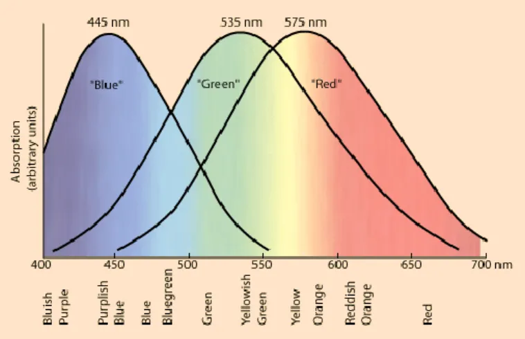
The rods have high sensitivity to light and low visual acuity as they provide vision in dim light. They have only one type of opsin and therefore allow a monochromatic vision : they are sensitive to blue-green light with a peak sensitivity around 500 nanometers ( nm).
The cones have rather low sensitivity and high visual acuity , since they function best in relatively bright light. They are also able to perceive finer detail and more rapid changes in images, because their response times to stimuli are faster than those of rods [17]. Contrary to the rods , cones are of three types and have different photopigments in that they allow the color vision .
Depending on the exact structure of the molecule opsin , are maximally sensitive to short wavelengths , medium and long . There are 3 types of cones which we will refer to as the short-wavelength
sensitive cones,s-cones, the middle-wavelength sensitive cones M-cones and the long-wavelength sensitive cones, L-cones for short . One can imagine that we see red when the radiation excites more cones with maximum sensitivity at 560 compared to those with a maximum sensitivity at 530. At the wavelengths where these two types of cones are approximately equally sensitive , we see yellow, where instead the excitation of the second type of cones ( with a peak at 530 nm ) is greater than the first ( 560 nm ) we see green.
20
2.2.7 Optic nerve
The optic nerve is located in the back of the eye. It is also called the second cranial nerve or cranial nerve II. It is the second of several pairs of cranial nerves. Although the optic nerve is part of the eye, it is considered to be in the central nervous system. The job of the optic nerve is to transfer visual information from the retina to the vision centers of the brain via electrical impulses. The optic nerve is made of ganglionic cells or nerve cells. It consists of over one million nerve fibers. Our blind spot is caused by the absence of specialized photosensitive cells, or photoreceptors, in the part of the retina where the optic nerve exits the eye.
Between the fibers of the optic nerve run along also blood vessels that bring nutrients to the various retinal layers and gangliar cells.
Fig. 11: the three different types of cones and the three corresponding wavelengths.
21
2.3 A review of artificial vision
As mentioned before, several approaches had been proposed to simulate the natural vision. The human visual system (HVS) is highly space-variant in sampling, coding processing and understanding the physical world, because there are non-uniformly distributed photoreceptors at the retina. A high- concentration cone photoreceptors is located at the point of gaze. Departing from the point of gaze or central fovea, cone photoreceptors decrease significantly, while rod photoreceptors increase markedly [18].
Log-polar imaging consists of a type of methods that represents visual information with a space-variant resolution inspired by the visual system of mammals. This can be reached with physical or computational solutions.
2.3.1Physical approaches
Sandini’s [19] paper proposes a retina-like sensor characterized by a space-variant resolution similar to that of the human retina.
Of all possible implementations of space-variant sensors the one described in this paper is the so-called log-polar structure [1-3]. In this schema a constant number of photosites are arranged over
22 concentric rings (the polar part of the representation) giving rise to a linear increase of the receptor's spacing with respect to the distance from the central point of the structure (the radius of the concentric rings). A possible implementation of this arrangement is shown in Figure 12.
Because of the polar structure of the photosensitive array and the increasing size of pixels in the periphery, retina-like sensor, do not provide images with a standard topology. In fact in the log-polar format a point in the image plane at polar coordinates (x ,y ) is mapped into a Cartesian plane (log(x),y ). It is worth noting that the mapping is obtained at no computational cost, as it is a direct consequence of the photosites array and the read-out sequence.
The topology of a log-polar image is shown in Figure 2. Note that radial structures (the petals of the flower)
correspond to horizontal structures in the log-polar image. In spite of this seemingly distorted image, the mapping is conformal and, consequently, any local operator used for "standard" images can be applied without changes[20].
A first solid-state realization of a log-polar sensor was realized at the end of '90 using CCD technology [21].
Such technology had some disadvantages that have been solved through CMOS (the size of the smallest possible pixel was about 30 μm , the sensor had a blind “wedge” because of a read-out shift register, the increase of pixel's size with eccentricity posed some problems because of the relationship between the sensitivity of pixels and their size [22]).
Figure 12: Layout of receptor's placing for a log-polar structure composed of 12 rings with 32 pixels each. The pixels marked in black follow a logarithmic spiral.
Figure 13: Left: space variant image obtained by remapping an image acquired by a log-polar sensor. Note the increase in pixels size with eccentricity. Right: Logpolar image acquired by a retina-like sensor. Horizontal lines in the log-polar image are mapped into rings to obtain the re-mapped image shown on the right
23 For example, this pixel has a logarithmic response to illumination and, consequently, the sensitivity of the largest and smaller pixels is comparable.
More their most recent CMOS implementation was realized using a 0.35 μ m technology that allowed to have a fourfold increase in number of pixels without increasing the size of the sensor and have a better coverage of the central part (foveal) removing some of the drawbacks of the previous implementation.
Thanks to such a techonology it has been possible to reach a high value of the parameter Q (ratio between sensor's size and size of the smallest pixel) without reducing the figure R (the ratio between the largest and the smallest pixels ) measuring the "space-variancy" of the sensor.
Except that improvements, such a device has the main limit in the central area, exactly where resolution should be maximum, is not completely covered by sensors.
2.3.2 Computable methods
Zoujing [23] presents a new computable method to simulate distribution of retina photoreceptors for space variant resolution imaging. When a human observer gazes at a point in a real word image, a variable resolution image, as a biological result, is transmitted through the front visual channel into the high level processing units in the human brain. By taking advantage of this fact, this no-uniform resolution processing can be applied to digital imaging or video transmission. This application would be valuable if the network connection between the user and the image server is slow. In this case image compression algorithms can be vital. However, in the process of simulated HVS (human vision system) perception, high-fidelity vision would be maintained around the point of gaze, while departing from it, varied resolution information is transmitted according to the fact of HVS perception. From the information processing point of view, image processing simulation biological retinal model is more efficient than traditional methods. The motivation behind foveation image procession is that there exists considerable high-frequency information redundancy in the peripheral regions, thus a much more efficient representation of images can be obtained by removing or reducing such redundancy for implementing low bandwidth method using Gaussian multi-resolution pyramids (filters).
24 A constant resolution image had been decomposed in sub-images, called pyramidal levels,
characterized by a lower information content. If we have an uniformly sampled image (same distance between pixel in all directions) and we want to simulate a non-uniformly sampling process (as in the retina where photoreceptors density decrease toward the periphery) is necessary to spatially filter the image at different spatial frequencies. In order to generate space variant imaging simulating foveates images, an original uniform-resolution image is decomposed into a Gaussian pyramid of several levels. Only a filter had been used, but the original image has been sub-sampled repeatedly: a region of smaller spatial extent is taken from each higher-resolution level of the pyramid. For every level the number of column and rows had been halved respectively. The Gaussian filter is chosen in each level because blurred versions of the original image were required for certain portion of the foveation process. The cut-off frequency, w0, had been chosen in order to be changed and simulate the
photoreceptors decrease in the retina with eccentricity. The Gaussian filter is a low pass filter so it attenuates frequencies higher than the cut-off frequencyw0. To create sub-images w0 had been
increased at each level. A four levels image is composed by four images. The first is the original image and the others are obtained using the Gaussian filter (through convolution) with a higher cut-off frequency for each level. In this way the images with the smallest number of pixel has the maximum resolution.
A typical Gaussian function is shown as:
Where l (x,y) denotes the distance between a given point and the center in processing image. In order to apply the foveation framework described above to image compressing, they conceive a standard framework for transmitting the necessary data. In addition to the pyramid encoding, the image data had been compressed before transmission using some linear encoding mechanism such as Huffman coding (a linear code allows the receiver to unpack the image data progressively as it is received, without having to wait for the entirety of the data to be received).
Finally such a methodology is limited by the rate of transmission through a common wi-fi network
Fig.14 : Multi-resolution pyramid based on Gaussian low- pass filter and foveated procession.
25 and has a not negligible computational complexity in terms of development of the entire pyramidal structure and in data transmission.
In his paper Traver surveys the application of log-polar imaging in robotic vision, particularly in visual attention, target tracking, egomotion estimation, and 3D perception.
Both natural and artificial visual systems have to deal with large amounts of information coming from the surrounding environment. To address this problem the visual system of many animals exhibits a non-uniform structure, where the receptive fields1 represent certain parts of the visual field more densely and acutely. In the case of mammals retinas present a unique high resolution area in the center of the visual field, called the fovea. The distribution of receptive fields within the retina is fixed and the fovea can be redirected to other targets by ocular movements. The same structure is also
commonly used in robot systems with moving cameras [25] [26]. Log-polar mapping is a geometrical image transformation that attempts to emulate the topological reorganization of visual information from the retina to the visual cortex of primates. There are different ways to obtain log-polar images using software and/ or hardware-based solutions
They believe that using sensors with sensitive elements arranged following a log-polar pattern has a great drawback . It is represented by the technical obstacles faced either during their design and construction or even during their usage, which limits the range of applications. Furthermore, the hardcoded geometry layout makes it very difficult, if not impossible, to experimenting with different sensor parameters.
At the same time, even if a software approach has a remarkable flexibility in setting the log-polar parameters they have the unavoidable cost of obtaining the log-polar image from the Cartesian image. This may be a drawback in real applications. To overcome this problem and still count on the
flexibility of software, they believe that the best solution is an intermediate one. It is represented by virtual log-polar sensors [27] [28]. This alternative still needs Cartesian images as input, but the implementation of the log-polar mapping is performed in special-purpose hardware cards, thus making the conversion faster while providing the possibility of setting the sensor parameters.
Finally, Cormak proposes a paper where he focuses on the processing done by the early levels of the human vision system to highlight the importance of computational models of the human perception of the world.
He shows that the main functions performed by the major structures of human vision are filters. Lowpass filtering by the optics and sampling by the receptor mosaic, the retina and the thalamus cells filtering. The photoreceptors themselves filter along the dimension of time and wavelength and the LGN cells (lateral geniculate nucleus of the thalamus) in 2D Fourier plane are circularly symmetric bandpass filter. Gangliar cells are spatio-temporal bandpass filter. Finally cells in the primary visual
26 cortex can be thought of as banks of spatiotemporal filters that tile the visual world in several
dimensions and, in so doing, determine the envelope of information to which we have access.
For each level, mathematical models that have been developed. That being so, the author reaffirms the importance of a computational approach because it’s the best way to describe the main biological structure and their functions of the human vision system.
References
[1] “The Eye: The Physiology of Human Perception, edited by Kara Rogers Britannic, Educational Publishing].
[2] “Clinical anatomy of the eye”, Richard S. Snell, Michael A. Lemp, pubblicato da Blackwell Science, 1998].
[3] [4] [5] [7] Encyclopaedia Britannica.
[6] “Dictionary of Eye Terminology”. Cassin, B. and Solomon, S. Gainsville, Florida: Triad Publishing Company, 1990.
[8] “Anatomy and physiology of the human eyeball in the normal state”, dr. Maximilian Salzmann, stampato da The University of Chicago Press, 1912.
[9] http://retina.anatomy.upenn.edu/~lance/eye/eye.htm.
[10] “Dynamic fields and waves”, Andrew Norton, The Physical World course, Institute Of Physics Publishing, 2000, p.137
[11] Henkind et al., 1979. [12] Polyak, 1941.
[13] “Cell density ratios in a foveal patch in macaque retina”. Ahmad et al., 2003.. Vis.
Neurosci. 20:189-209).
[14 ] “Light:Student Guide and Source Book” Smithsonian/The National Academies, . Carolina Biological Supply Company, 2002. ISBN 0-89278-892-5.
[15] “Experiencing Sensation and Perception”, Krantz, John H. (1 October 2012). Pearson
Education. ISBN 978-0-13-097793-9.OCLC 711948862. Retrieved 6 April 2012. Available online ahead of publication.
[16] Balashov and Bernstein, 1998.
[17] “Principles of Neural Science” (4th ed.). Kandel, E.R.; Schwartz, J.H, and Jessell, T. M. (2000). New York: McGraw-Hill. pp. 507–513.
27 [18] Wandell, 1995; Cormack,2000.
[19 ] “A retina-like CMOS sensor and its applications”. Sandini, Giulio, et al. “Sensor Array and
Multichannel Signal Processing Workshop”. 2000. Proceedings of the 2000 IEEE. IEEE, 2000.
[20 ] “Logarithmic Spiral Grids for Image Processing and Display”. Weiman, C.F.R. and G. Chaikin, Comp. Graphic and Image Process.,, 1979. 11: p. 197—226.
[21] [22] “A Foveated Retina-like Sensor Using CCD Technology” Spiegel, J.V.d., et al.,. 1989, De Kluwer.
[23] “Simulated distribution of the retinal photoreceptors for space variant resolution
imaging”.Zoujin Li, W. Shi and Zhi Zhong,
[24 ] “A review of log polar imaging for visual perception in robotics”.V. Javeier Traver, Alexandre Bernardino,
[25] “Binocular tracking: Integrating perception and control”, A. Bernardino, J. Santos-Victor, IEEE Transactions on Robotics and Automation 15 (6) (1999) 1080_1094.
[26] “A miniature space-variant active vision system”, B. Bederson , Ph.D. Thesis, New York University, 1992.
[27] “A programmable video image remapper, in: SPIE Conf. on Pattern Recognition and Signal
Processing, in: Digital and Optical Shape Representation and Pattern Recognition”, vol. 938, 1988, pp. 122_128 ”. T.E. Fisher, R.D. Juday,
[28] “VIPOL: A virtual polar-logarithmic sensor, in: Scandinavian Conf. on Image Analysis”, J.R. del Solar, C. Nowack, B. Schneider, SCIA, Finland, 1997, pp. 739_744”.
28
Chapter 3
LIGHT SCATTERING
As mentioned in the introduction, the filter we realized is based on the light scattering phenomenon by small spherical particles .
Place a filter which exploits the diffusion phenomenon in front of a vision system, such as a camera , allows us to obtain images perceived as " blurred.". This immediately call to mind the concept of foveal vision , where only the object gazed looks exactly in focus, whereas the whole environment that comes out of his little round arrives to the brain as a blurry image. Such a device seems to be the best solution to achieve our goal and that is to create a device to simulate human vision.
Therefore is essential to explain and classify the scattering in order to understand completely how the filter operate and then characterize it.
In addition to scattering is also necessary to introduce other basic concepts the phenomenon of scattering is intrinsically linked to . We will explain what is light by three theories, how it spreads and what polarization means. We will speak about the interaction of light with matter and in specific case of scattering , we focus on the parameters that characterize the small particles that give rise to this phenomenon.
3.1 Introduction to light
Light is part of the electromagnetic spectrum, the spectrum is the collection of all waves, which include visible light, Microwaves, radio waves (AM, FM,SW), X-Rays and Gamma Rays.
In the late 1600s important question were raised, asking if light is made up of particles or is it waves? Isaac Newton held the theory that light was made up of tiny particles. In 1678, Christian Huygens believed that light was made up of waves vibrating up and down perpendicular to the direction of the light travels and therefore formulated a way of visualizing wave propagation. This became know as “Huygens Principle”. Huygens theory was the successful theory of light wave motion in three dimensions.
29 At the time, some experiments conducted in light theory, both the wave theory and particle theory, had some unexplained phenomenon, Newton could not explain the phenomenon of light interference, this forced Newton’s particle theory in favour of the wave theory. This difficulty was due to the
unexplained phenomenon of light polarization- scientists were familiar with the fact that wave motion was parallel to the direction of wave, not perpendicular to the direction of wave travel, as light does. In 1803, Thomas Young studied the interference of light waves by shining light through a screed with two slits equally separated, the light emerging from the two slits, spread out according to Huygens’s. In 1900 Max Plank proposed the existence of a light quantum, a finite packet of energy which depends on the frequency and velocity of the radiation.
In 1905 Albert Einstein had proposed a solution to the problem of observations made in the behavior of light having characteristic both wave and particle theory. From work of Plank in emission of light from hot bodies, Einstein suggested that light is composed of tiny particles called photons and each photon has energy.
Light theory branches in to the physics of quantum mechanics, which was conceptualized in the twentieth century. Quantum mechanics deals with behavior of nature on the atomic scale or smaller. As a result of quantum mechanics, this gave the proof if the dual nature of light and therefore not a contradiction.
In general a wave is a disturbance or variation that transfers energy progressively from point to point in a medium and that may take the form of an elastic deformation or of a variation of pressure, electric or magnetic intensity, electric potential, or temperature. Waves are important because all the
information that we receive, auditory and visual, are transmitted through them. The light and sound have in fact typical properties of the waves and in a simple treatise can be considered as waves. [1] In general there are two types of waves: transverse waves in which the displacement, i.e. the
movement caused by the disturbance, is perpendicular to the direction in which the perturbation moves and longitudinal waves where the displacement is parallel to the direction of propagation.
Mathematically, the simplest waves are "periodic waves" that continue undisturbed for long distances ideally for infinite times.
The sine wave is the fundamental waveform in nature. When dealing with light waves, we refer to the sine wave. To describe sin we need only to know its frequency and the speed of the disturbance, called phase velocity, in the medium.
The frequency is the number of peaks that will travel past a point in one second and is set by the source.
As consequence of the conservation of energy, the frequency does not change as the wave travels from one medium to another. Since the frequency remains unchanged, the wavelength of a wave is different from a medium to another. Moreover, the speed of propagation through a medium is lower than in the vacuum.
30 λ=
f v
This equation tells us that for a given speed of propagation, the higher the frequency and the smaller the wavelength.
There are different types of waves, for example, a wave on water of a lake, waves of a vibrating string, sound waves in the air that allow us to feel, radio waves, TV waves or X-rays. The last three examples are electromagnetic waves, while the others are mechanical waves. Only a small portion of the
electromagnetic spectrum is visible to the human eye and that is what we usually call light. In this context, the equation seen previously, becomes:
λ = f c
This shows an important property of electromagnetic waves: the speed of propagation is the same for all waves and is equal to the speed of light in vacuum.[2]
As each wave also the wave that represent light has an amplitude that corresponds to the brightness, a wavelength, which affects the color of the light itself, and an angle called polarization.
In classic electromagnetism a radiation is wave motion phenomenon because of an electric (E) and magnetic (B) fields that oscillate perpendicular to the direction of wave travel and perpendicular to each other.
This diagrams show a plane linearly polarized EMR wave propagating in xy plane. The electric field is in a vertical plane and the magnetic field in a horizontal plane.
The two types of fields in EMR waves are always in phase with each other with a fixed ratio of electric to magnetic field intensity, η called wave impedance.
31 y x
h
e
The wave impedance depends on the electrical and magnetic characteristics of the medium in which the wave propagates according to the formula:
In the vacuum: 377 0 0
3.2 Maxwell’s Equations
Maxwell's equations, whose name is due to James Clerck Maxwell, Maxwell’s equations are four partial differential equations that relate the Electric Field (E) and magnetic field (B) to the charge (ρ ) and current (J) densities that specify the fields and give rise to electromagnetic radiation - light. Maxwell's equations do not contain any information about the properties of the medium. However, under the action of the electromagnetic field, the medium polarizes, it magnetizes and if it is conductor, is crossed by conduction currents. In turn, these affect the field and must be taken into account by (through) additional equations, the constitutive relations.[3]
Suppose to be in free space ( linear, isotropic, homogeneous and non-dispersive medium ), in such a medium the constitutive relations are:
) , ( ) , (r t 0e r t d ) , ( ) , (r t 0h r t b
32 In which
d
andb
are auxiliary fields; e electric field,h
magnetic field. ε0 and μ0 are two universalconstants, called the permittivity of free space and permeability of free space, respectively. In vacuum ε0
1/(36π)∙10-9
[F/m], and μ0=4π∙10 -7
[H/m]. Maxwell’s equations in time domain are:
)
,
(
)
,
(
b
r
t
t
t
r
e
)
,
(
)
,
(
)
,
(
d
r
t
j
r
t
t
t
r
h
)
,
(
)
,
(
r
t
r
t
d
0
)
,
(
b
r
t
In which
j
is the electric current density the electric current per unit area of cross section ΔS , where S tends to zero. ρ the electric charge per unit volume, where ΔV tends to zero.The electric density
j
can be divided in two parts:)
,
(
)
,
(
)
,
(
r
t
j
1r
t
j
0r
t
j
In which
j
1is produced by electromagnetic field andj
0 by generators.We can see that Maxwell's equations relate the vectors field with the sources of the field itself. They are a set of four equations ( two vector and two scalar ) corresponding to eight scalar equations . Is immediately evident that the number of unknowns is greater than the number of equations . If density of free charge and current density supported by the generators are assigned, the unknowns variables are represented by the component of the vectors . We should note also that Maxwell's equations are not all linearly independent . The system of Maxwell is therefore indeterminate ; it can be determined if we consider others relations about the medium the fields arise. These are the constitutive relations previously defined. Now suppose to be in absence of sources , and considering the constitutive relations , the system of Maxwell's equations become :
)
,
(
)
,
(
0h
r
t
t
t
r
e
)
,
(
)
,
(
0e
r
t
t
t
r
h
0
))
,
(
(
0
e
r
t
) , ( )) , ( (0h r t r t 33 Assuming that the fields e and
h
, usually functions of x, y, z and t, depend only on the z-axis and on the time t, performing calculation, we obtain D'Alembert’s equation:2 2 2 2 2 z e c t ex x
With 0 01
c
And the solution is:
)
(
)
(
2 1z
ct
f
z
ct
f
e
x
Where f1 and f2 are functions that depend on the specific problem we are dealing with. Since the medium in question was supposed to be linear, the principle of superposition can be applied. We can therefore consider only the first part of the solution:
)
(
1
z
ct
f
e
x
3. 3 Particle theory of light
Newton proposed that light consists of little particles, which he referred to as corpuscles, with energy and momentum. When a light particle is deep within a medium, such as water or glass, it is
surrounded on all sides by equal numbers of these particles. Suppose there is an attractive force
Fig. 1. A wave travelling in the x direction with unchanging shape and with velocity c. at time t=0 the shape is ψ=f(x) and at time t it is ψ=F(x - ct)
34 between the light particles and the matter particles. Then deep within a medium, these forces cancel each other out and there is no net force on the light particle. Then, according to Newton’s first law, the light particle will continue moving in a straight line since no net force acts on it.
Many known properties of light could be explained easily by a particle model. For example it was known that when light reflects from a smooth surface, the angle of incidence is equal to the angle of reflection.
As we shall see, a key property for the particle theory is refraction.
Instead, if the body is porous ( constituted in such a way that between atom and atom there are wide gaps) the particles pass through it. As they suffer the gravitational attraction , are accelerated. Because of this, the speed of light is greater in a denser medium and the particles are diverted (in straight directions) with compared to the original trajectory.
Newton concluded that light is composed of coloured particles which combine to appear white. He introduced the term 'colour spectrum' and, although the spectrum appears continuous, with no distinct boundaries between the colours, he chose to divide it into seven
His explanation for the fact that a prism separates a beam of white light into the colors of the rainbow was simple. We have seen that red light refracts least, and violet light most. Newton stated that the mass of the
light particle varied with color. Red light particles have more mass than violet, consequently they will be deflected less upon crossing an interface between materials. He assumed all light particles
experience the same force on crossing an interface. What differs among them is their inertia. Red light particles with more inertia will be deflected less by the same force than violet light particles.
35
3.4 Quantum theory
According to modern quantum physics created by Einstein, the particles that make up atoms are made from tiny concentrated energy, of those many have a dual nature : wave and particle . Precisely the matter at the subatomic level has the typical characteristics of the waves and only when we observe this the matter has a corpuscular behavior .
In the quantum theory of light, light exists as tiny packets called photons. So the brightness of the light corresponds to the number of photons , the color to the energy contained in each photon and four letters (x, y, z, t ) indicate the polarization .
We might ask which interpretation is correct. Both , actually.
It seems that the electromagnetic radiation can have both wave and particle properties.
For the purposes of this paper , we will discuss only the light from the point of view of the wave , also remembering that they're both valid.
The light is defined as the electromagnetic radiation that has a wavelength ranging from 330
nm(violet) to about 770 nm (red) and may be perceived by the normal unaided human eye. Thus light takes up a very small portion of the spectrum . The visible spectrum ranges from the long radio waves, which are often thought of as the propagation and the oscillating electric fields , short X-rays and gamma rays, which are imagined as energetic particles . It’s important to remember that there is no fundamental difference between one and another portion of the electromagnetic spectrum . A radio wave is a broad- wavelength and x-rays on the other hand have short wavelength , but both are electromagnetic radiation and their behavior is governed by the same rules.
But if all these waves are basically the same thing , we might ask why we do not see radio waves as we see the light? Or, why do we need special infrared lamps to warm things up ? Although the various portions of the electromagnetic spectrum are governed by the same laws, their wavelengths and their different energies implies that they have different effects on matter. Radio waves for example have a length so wide and an energy that our eyes are not able to receive and they pass through our bodies . An antenna wire with a special electronics to capture and amplify radio waves is necessary.
Similarly, the infrared radiation is easily absorbed by the material and converted into heat, X-rays instead have a wavelength which passes through soft tissue but is stopped by the bone. The
exceptional variety of the electromagnetic spectrum is the result of the same law applied to different wavelengths and energies. The quantum nature of a wave, which is responsible of the obvious differences between the gamma ray and a radio waves, occurs only when the waves interact with matter. It has been shown that the waves exchange energy and momentum with their generators and absorbers only in discrete packets, in accordance with the quantum laws. These packets of energy, called quanta, are the photons.
36
3.5 Wave propagation
If we consider light waves radiating from a point source in a vacuum as shown in Fig. 3, it is apparent that at a given instant each wave front is spherical in shape, with the curvature (reciprocal of the radius) decreasing as the wave front travels away from the point source. At a sufficient distance from the source the radius of the wave front may be regarded as infinite. Such a wave front is called a plane wave [4]
The distance between successive waves is of course the wavelength of the radiation. The velocity of propagation of light waves in vacuum is approximately 3 x 1010 cm/s. In other media the velocity is less than in vacuum. In ordinary glass, for example, the velocity is about two thirds of the velocity in free space. The ratio of the velocity in vacuum to the velocity in a medium is called the index of refraction of that medium, denoted by the letter n.
Index of refraction n = velocitv in vaccum / velocity in medium
Both wavelength and velocity are reduced by a factor of the index; the frequency remains constant. Ordinary air has an index of refraction of about 1.0003, and since almost all optical work (including measurement of the index of refraction) is carried out in a normal atmosphere, it is a highly convenient convention to express the index of a material relative to that of air(rather than vacuum), which is then assumed to have an index of exactly 1.0.
If we trace the path of a hypothetical point on the surface of a wave front as it moves through space, we see that the point progresses as a straight line. The path of the point is thus what is called a ray of light.
Such a light ray is an extremely convenient fiction, of great utility in understanding and analyzing the action of optical systems.
We know that light is an electromagnetic wave and therefore can not propagate in a straight line, but if the size of an obstacle bigger than wavelength, light rays are defined to propagate in a rectilinear path. The propagation occurs along rays that are lines perpendicular to the wave front (wave surface).
Fig.3: light waves radiated from a point source in an isotropic medium take a spherical form; the radius of curvature of the wave front is equal to the distance from the point source. The path of a point on the wave front is called a light ray and in an isotropic medium is a straight line. Note also that the ray is
37 Geometric optics studies therefore the "behavior" of rays, as if light was formed by particles moving along these rays.
Let us now consider a plane wave front incident upon a plane surface separating two media, as shown in Fig. 1.4. The light is progressing from the top of the figure downward and approaches the boundary surface at an angle. The parallel lines represent the positions of a wave front at regular intervals of time. The index of the upper medium we shall call n1 and that of the lower n2. From Eq. 1.1, we find
that the velocity in the upper medium is given by v1 = c/n1 (where c is the velocity in vacuum ≈ 3
x1010 cm/s) and in the lower by v2 = c/n2. Thus, the velocity in the upper medium is n2/n1 times the
velocity in the lower, and the distance which the wave front travels in a given interval of time in the upper medium will also be n2/n1 times that in the lower.
In Fig. 1.4 the index of the lower medium is assumed to be larger so that the velocity in the lower medium is less than that in the upper medium ( n2 > n1). At time t0 our wave front intersects the
boundary at point A; at time t1=t0+Δ t it intersects the boundary at B. During this time it has moved a
distance
t
n
c
t
v
d
1 1 1 eq. 1in the upper medium, and a distance
t
n
c
t
v
d
2
2 2 eq. 2in the lower medium.
Fig.4 : a plane wave front passing through the boundary between two media of differing indices of
38 In Fig. 5 we have added a ray to the wave diagram; this ray is the path of the point on the wave front which passes through point B on the surface and is normal to the wave front. If the lines represent the positions of the wave at equal intervals of time, AB and BC, the distances between intersections, must be equal. The angle between the wave front and the surface (I1 or I2) is equal to the angle between the ray (which is normal to the wave) and the normal to the surface XX′.
Thus we have from Fig. 5
2 2 1 1
sin
sin
I
d
BC
I
d
AB
eq. 3aand if we substitute the values of d1 and d2 from Eq. 3, we get
2 2 1 1
sin
n
sin
I
t
c
I
n
t
c
eq. 3bwhich, after canceling and rearranging, yields
2 2 1
1
sin
I
n
sin
I
n
eq. 4This expression is the basic relationship by which the passage of light rays is traced through optical systems. It is called Snell’s law after one of its discoverers. Since Snell’s law relates the sines of the angles between a light ray and the normal to the surface, it is readily applicable to surfaces other than the plane which we used in the example above; the path of a light ray may be calculated through any surface for which we can determine the point of intersection of the ray and the normal to the surface at
Fig. 5: Refraction of a wave (ray) at the interface between two media of different refractive indices.