Università degli Studi di Pisa - Dipartimento di Scienze della Terra Scuola di Dottorato di Ricerca in Scienze di Base Galileo Galilei
Programma di Scienze della Terra XXV Ciclo - 2010-2012
Dissertazione finale
Carmen Capalbo
MINERALS OF THE HOLLANDITE SUPERGROUP:
CRYSTAL-CHEMISTRY AND THERMAL BEHAVIOR
Tutor: Referees:
Prof. Marco Pasero Prof. Luca Bindi
TABLE OF CONTENTS
Introduction ... 1
Chapter 1: Tunnel oxides ... 7
1.1 Basic structural features ... 7
1.2 Ramsdellite: polysomatic issue... 27
1.3 Structural details ... 28
1.3.1 Octahedral distortion ... 28
1.3.2 Cations distribution in 2 x 2 tunnels ... 34
1.3.3 Theoretical occupancy in 2 × 2 tunnels ... 41
1.3.4 Cations distribution in larger tunnels ... 46
Chapter II: Minerals of the hollandite supergroup ... 52
2.1 Introduction ... 52
2.2 Manganate group ... 52
2.3 Titanate group ... 55
Chapter III: Nomenclature adjustments in minerals of the hollandite supergroup ... 58
3.1 Foreword ... 58
3.2 Introduction ... 58
3.3 Recalculation of the ideal chemical formula ... 60
3.4 Minerals of the hollandite supergroup: coronadite group ... 62
3.4.1 Coronadite... 62
3.4.2 Hollandite ... 62
3.4.3 Cryptomelane ... 63
3.4.4 Manjiroite... 64
3.4.5 Strontiomelane ... 64
3.5 Minerals of the hollandite supergroup: priderite group ... 65
3.5.1 Priderite ... 65
3.5.3 Mannardite ... 65
3.5.4 Ankangite ... 66
3.4.5 Henrymeyrite ... 66
3.6 Potential new mineral species in the hollandite group ... 67
3.7 New classification of the minerals of hollandite supergroup ... 68
Chapter IV: Cation displacement in minerals of the hollandite supergroup ... 69
4.1 Introduction ... 69
4.2 Cryptomelane from Montalto di Mondovì ... 71
4.2.1 Geological outline ... 71
4.2.2 Structural refinement ... 73
4.3 Cryptomelane from Sitapur Mine ... 77
4.3.1 Geological outline ... 77
4.3.2 Structural refinement ... 78
4.4 Cryptomelane from Kàjilidongri ... 82
4.4.1 Geological outline ... 82
4.4.2 Structural refinement ... 84
4.5 Ferrihollandite from Ultevis ... 87
4.5.1 Geological outline ... 87
4.5.2 Structural refinement ... 88
4.6 Hollandite from Nancy mine ... 90
4.6.1 Geological outline ... 90
4.6.2 Structural refinement ... 91
4.7 Hollandite from Monte Corchia ... 95
4.7.1 Geological outline ... 95
4.7.2 Structural refinement ... 96
4.8 Ferrihollandite from Kàjilidongri mine ... 100
4.8.1 Geological outline ... 100
4.9.2 Structural refinement ... 106
4.10 Mannardite from Monte Arsiccio ... 109
4.10.1 Geological outline ... 109
4.10.2 Structural refinement ... 110
Chapter V: HT-LT structural studies of minerals of the hollandite supergroup ... 114
5.1 Introduction ... 114
5.2 Ferrihollandite thermal behavior ... 115
5.2.1 General features at LT and HT conditions ... 115
5.2.2 Octahedral regularization ... 125
5.2.3 Tunnel cations distribution in LT, RT and HT conditions ... 130
5.3 Mannardite thermal behavior ... 134
5.3.1 General features at LT and HT conditions ... 134
5.3.2 Tunnel cations distribution in LT, RT and HT conditions ... 136
Chapter VI: Water content and phase transition induced by temperature in minerals of the hollandite supergroup. ... 141
6.1 Introduction ... 141
6.2 Modeling approach ... 142
6.2.1 Ferrihollandite from Vagli ... 142
6.2.2 Mannardite from Monte Arsiccio ... 146
6.3 TG/DSG analysis ... 148
6.4 IR analysis ... 152
VII Conclusions... 156
Ringraziamenti ... 164
APPENDIX II: Recalculation of the ideal chemical formula of minerals of the hollandite
supergroup ... 177
APPENDIX III: SEM/EDS and EMP analyses ... 188
APPENDIX IV: Structural data at RT conditions ... 197
APPENDIX V: Structural data at LT-HT conditions ... 221
APPENDIX VI: Structural data of anhydrous and hydrated model of ferrihollandite from Vagli and mannardite from Monte Arsiccio. ... 241
Introduction
All solid crystalline materials can be considered as consisting of atoms linked by chemical bonds of different kind. Some of them may present peculiar structural arrangements characterized by the presence of pores with variable size. These materials are divided into three categories (microporous, mesoporous, and macroporous) based on the dimensions of the pores. In an ordered microporous, mesoporous and macroporous material, the pores can accommodate a sphere with diameter ranging between 0.25 and 2 nm, 2 and 50 nm, and more than 50 nm, respectively, and are arranged in an ordered manner (McCusker et al., 2003). These pores can be empty or occupied by guest chemical species.
In most cases, the hosted atoms are arranged periodically with long-range order. However in some materials the hosted atoms display only short-range order.
The highest possible symmetry for a microporous, mesoporous and macroporous structure is the symmetry of its topology (topological symmetry). Although the symmetry of a particular material can correspond to the topological symmetry, it is often a subgroup thereof. The lowering of symmetry and the distortions of these structures due to the ordered distribution of the guest species within the pores, as well as the distortions due to the ordered distribution of the framework cations, are common.
A pore that is infinitely extended in one dimension and that may host atoms along its length is called a “tunnel”.
One of the most relevant subgroups in the frame of microporous materials with tunnel structure belongs to the large family of oxide minerals, and is that of the so-called “tunnel oxides”.
The tunnel oxides are mainly manganese oxides, although a set of titanium oxides display the same basic structural features. The most commons oxidation states of manganese in natural systems are +2, +3, +4, +6, +7, although all the oxidation states from +1 to +7 have been observed. In tunnel oxides, manganese occurs as Mn4+, Mn3+, Mn2+, with the former being the dominant form. Tetravalent manganese typically
displays octahedral coordination, and the [Mn4+O6] octahedra may build up many framework structures with tunnel shape.
In these compounds the octhaedra are arranged in edge-sharing chains, which in turn link together, again by edge-sharing, to construct walls, whose widths depend on the number of the involved chains. Corner-sharing of these walls in near perpendicular directions generate a number of different tunnel structures with either square or rectangular outline, depending on the dimensions of the walls, e.g. 1 × 1, 2 × 2, 2 × 3, etc. (each number represents the single, double, triple, etc., edge-sharing chain) (Pasero, 2005).
Starting from the basic formula of manganese dioxide, Mn4+O2, incorporation of monovalent and divalent cations is allowed within the tunnels by substitution of Mn4+ by lower valence cations such as Mn3+, Fe3+, V3+, Cr3+, etc.. The same applies to TiO2 oxides. Moreover, water molecules can find place within the tunnels, too.
It must be noted that some controversies occurred in literature as regards the reduced form of Mn in these minerals (Mn2+ or Mn3+).However, it is today accepted, on the basis of chemical argument and detailed X-ray spectroscopy studies, that reduced Mn is essentially Mn3+ (Yanchuck & Povarennykh, 1975a,b; Post et al., 1982). The generic substitutions that involve these minerals can be expressed by the summarizing formula:
A+x(M4+1-xM3+x)O2 or A2+x(M4+1-2xM3+2x)O2 where A = Na+, K+, Rb+, Ba2+, Pb2+, Mg2+, Zn2+;
M3+ = Mn, Fe, V, Cr, Al; M4+ = Mn or Ti.
Because of the open structure of tunnel oxides and the capability they have to incorporate extra-framework cations, there is a considerable interest in the use of these materials (and synthetic analogues) as catalysts, cation exchangers, and immobilization agents. Moreover, these materials exhibit a variety of tunnel shapes and sizes, thus
oxides are also known as Octahedral Molecular Sieves (OMS), a terminology very similar to ZMS, which is applied to zeolite-like molecular sieves.
The technological importance and the wide range of applications of tunnel oxides include:
- The trapping and the immobilization of radioactive wastes: Ringwood et al. (1979) synthesized a compound with 2 × 2 tunnel framework and composition BaTi6Al2O16 [similar to that of hollandite, BaMn8O16, a Mn-oxide with 2 × 2 tunnel shape] called Synroc®, which was able to incorporate radioactive waste elements, and especially radioactive cesium.
- Natural sinks for heavy metals and other trace elements in soils, aquatic sediments and contaminated waters from mines and other industrial activities (Whitney, 1975; Lind & Hem, 1993; Prusty et al., 1994). Ghoneimy (1997) discussed the capacity of cryptomelane (KMn8O16, 2 × 2 tunnel oxide) to adsorb Co2+ and Zn2+. Randall et al. (1998) showed that cryptomelane is able to sorb two thirds of available cadmium from solution at pH as low as 2.0.
- Additives to livestock feed and plant fertilizer (Post, 1999). - One-dimensional ionic conductor (Michiue et al., 2000).
Moreover, tunnel oxides are of considerable scientific interest in pure geosciences: potassium feldspar (KAlSi3O8) and others alkali aluminosilicates and aluminogermanates assume 2 × 2-type structure at very high pressure, and hence these phases may represent a major constituent of the Earth's mantle (Ringwood et al., 1967b). Ringwood et al. (1967a) described in detail a high-pressure (9 GPa) hollandite-type modification of K-feldspar with octahedrally coordinated Si4+. This represented, at that time, the second known example of a compound with [6]Si after stishovite.
Besides their many applications, tunnel oxides are very common in nature. A potentially resource for their formation is provided by manganese oxides that are found in a wide variety of geological settings and are nearly ubiquitous in soils and sediments. Manganese oxides with variable morphology, chemistry, and physical properties occur
in different environments throughout the world: fine aggregates, veins, desert varnish as coating on the mineral particles and rock surfaces (in arid and semiarid regions) (Fig. 1), marine and fresh-water concretions, crusts, dendrites (Fig. 2) (Potter & Rossman, 1979; Post et al., 1999).
Moreover, fine aggregates and coatings of manganese oxides have a large surface area that may further enhance their exchange capacity (Post et al., 1999). Anyhow, the most extensive depositions of manganese oxides occur in oceans, as nodules and microconcretions. In fact, Mn nodules have been found at almost all the dephts and latitudes in all the oceans: it has been estimated, for example, that they cover about 10-30% of the deep Pacific floor (Crerar & Barnes, 1974). Several processes are involved in the formation of oceanic nodules, including the precipitation of metals from sea-water, the remobilization of manganese in the water columns (diagenetic processes), the decomposition of basaltic debris by sea-water, the precipitation of metal hydroxides through the activity of microorganisms (biogenic processes), the derivation of metals as a product of continental runoff and hydrothermal and volcanic activity at mid-ocean spreading center (Menard & Shipek, 1958).
Typically, Mn nodules are brown-black, with subspherical-botroyoidal shape (Fig. 3), ranging between 5 and 10 cm in diameter, and grow concentrically around a core (Fig. 4). The core can be microscopically small and completely transformed into manganese minerals by recrystallization, or can be a small shell of a microfossil (radiolarian or foraminifer), a phosphatized shark tooth, a carbonate minerals fragment, a basalt debris, or even a fragment of earlier nodules.
Fig.4 - Manganese nodule spit in half. See how the concentric layers develop around a core. ©NYtimes.com
Since their technological importance and their abundance, a series of studies on a number of tunnel oxide minerals has been undertaken and discussed in this thesis, aiming at better understanding their properties.
Several X-ray diffraction experiments at ambient and non-ambient conditions will be shown, with special attention to the cation distribution within the tunnels and the thermal behavior of these minerals. A series of experiments carried out to identify the presence of water molecules within the tunnels will be described.
Besides, the revision of the nomenclature of a specific group of minerals with tunnel structures (hollandite supergroup, the major subject of this work) will be presented. All the experimental techniques used in this work are described in Appendix I.
Chapter 1: Tunnel oxides
1.1 Basic structural features
The basic building block for all the tunnel oxides is represented by either [Mn4+O6] or [Ti4+O6] octahedra (Fig. 1.1).
Fig. 1.1 - The basic building block for tunnel oxides framework, [Mn4+O
6] or [Ti4+O6] octahedra.
These structures consist of single, double, triple or quadruple chains of edge-sharing octhedra, giving rise to walls (even larger walls are known in synthetic compounds); these walls share corners with each other in the near perpendicular direction to produce frameworks with tunnels having square or rectangular cross section, depending on the dimension of the walls themselves (e.g. 1 x 1, 2 x 2, 2 x 3 etc.).
The ideal topological symmetry of the framework is tetragonal (for structures with the same dimensionality in the two directions, e.g., 1 × 1, 2 × 2, 3 × 3) or orthorhombic (for structures with tunnels having a rectangular outline, e.g., 1 × 2, 2 × 3, 3 × 4), but often the real symmetry is lower due to minor distortions of the framework and/or ordered distribution of the cations inside the tunnels (Pasero, 2005).
All the known minerals with tunnel structure are described below, in order of increasing complexity. For the sake of completeness, some synthetic compounds are also included.
1 × 1 tunnels - The smallest framework among the tunnel oxide minerals is adopted by pyrolusite (β-MnO2), the most stable and abundant polymorph of MnO2; the other natural polymorphs are ramsdellite (ε-MnO2) and nsutite (γ-MnO2); the latter, although presently recognized as a valid mineral species, is actually an intergrowth between pyrolusite and ramsdellite.
In pyrolusite, single columns of edge-sharing [Mn4+O6] octahedra share corners with neighboring columns to form a framework structure having tunnels with square cross sections, 1 x 1 wide (Fig. 1.2).
Fig. 1.2 - Polyhedral representation of the crystal structure of pyrolusite as seen along c (parallel to the octahedral chains).
The 1 × 1 tunnels are too small to accommodate any chemical species.
Because of its tunnel structure, pyrolusite typically occurs as acicular crystals (Fig. 1.3). Two structural forms of pyrolusite exist: a tetragonal one, which is characteristic of pyrolusite of primary origin (low-temperature hydrothermal deposits), and an orthorhombic modification characteristic of pyrolusite formed by alteration of ramsdellite [ε-MnO2] and manganite [γ-MnO(OH)] (Potter et al., 1979). A single-crystal X-ray diffraction refinement of the tetragonal form was performed by Baur (1976) who refined the structure in the space group P42/mmm, a = 4.3983(3), c = 2.8730(3) Å. The tetragonal structure is displayed, among minerals, also by rutile (TiO2) (Meagher & Lager, 1979), cassiterite (SnO2) and plattnerite (PbO2) (Palache et al., 1944), argutite (GeO2) (Yamanaka et al., 1991), the high-pressure polymorph of silica stishovite (SiO2) (Stishov & Popova, 1961), and sellaite (MgF2) (Palache et al., 1951).
Yoshino et al. (1992, 1993) and Kikuchi et al. (1994) showed that only pure pyrolusite has tetragonal symmetry. In fact, Rietvield refinement showed that Mn4+ is partially substituted by Mn3+, in the orthorhombic form (a = 4.4609, b = 4.6113, c = 2.7461 Å), with charge balance achieved by partial substitution of O by (OH), according to the general formula Mn4+1-xMn3+xO2-x(OH)x [the end-member with x = 1 is manganite, γ-MnO(OH)]. The same 1 × 1 structure topology with an orthorhombic symmetry is displayed by the mineral guyanaite [CrO(OH)], too (Milton et al., 1976).
1 × 2 tunnels – The 1 × 2 structure is adopted by ramsdellite, a natural occurring polymorph of MnO2 (Fig. 1.4).
Fig. 1.4 - Ramsdellite crystals in goethite matrix. Săo Luis quarry, Beja District, Portugal. ©Martins de Pedra
Fig. 1.5 - Structural scheme of ramsdellite as seen along c.
The first study of the crystal structure of ramsdellite was performed by Fleischer & Richmond (1943) who determined the orthorhombic symmetry and the approximate unit cell parameters. The structure was then worked out by Byström (1949), who refined it in the orthorhombic system, space group Pbnm and cell dimensions a = 4.533(5), b = 9.27(1), and c = 2.866(5) Å. Ramsdellite is isostructural with diaspore [Al3+O(OH)] (Fig. 1.6) and goethite [Fe3+O(OH)] (Fig. 1.7) (Ewing, 1935; Hoppe, 1940).
Fig. 1.6 - Group of diaspore crystals. Saga 1 Quarry, Telemark, Norway. ©Chinellato Matteo
Fig. 1.7 - Sprays of goethite from a spheroidal cluster of pyrite crystals. MacLeod mine, Ontario, Canada. ©John A. Jaszczak.
Subsequently, Gruner (1947) described a new mineral, groutite, [Mn3+O(OH)] (Fig. 1.8) which turned out to belong to the same diaspore group (Dent Glasser & Ingram, 1968). The unit cell parameters of all minerals of diaspore group are compared in Tab. 1.1.
Tab. 1.1 - Comparison between the unit cell parameters of minerals of diaspore group.
More recently, a more accurate structural refinement of ramsdellite through neutron and synchrotron X-ray diffraction has been carried out by Post et al., (2001), who also studied in detail the structural relationship along the join ramsdellite-groutite.
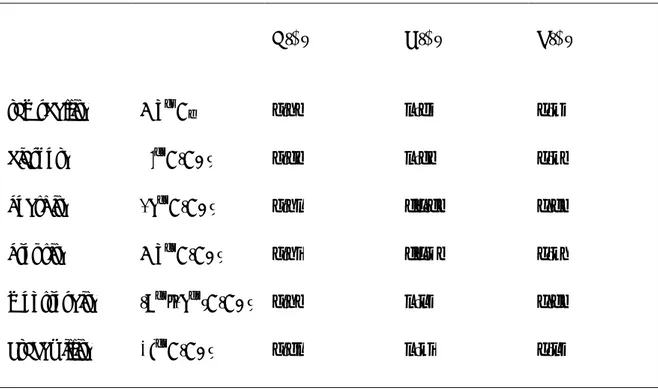
a (Å) b (Å) c (Å)
ramsdellite Mn4+O2 4.53 9.27 2.87
diaspore Al3+O(OH) 4.42 9.44 2.84
goethite Fe3+O(OH) 4.59 10.00 3.03
groutite Mn3+O(OH) 4.56 10.70 2.85
montroseite (V3+,Fe3+)O(OH) 4.54 9.97 3.03
Fig. 1.8 - Groutite crystals. Caveira Mine, Setùbal District, Portugal. ©Martins de Pedra
They observed that in ramsdellite Mn cations are displaced in respect to the center of the octahedra, probably due to the cation-cation repulsion between adjacent octhaedra. Moreover they found that half-way along the ramsdellite-groutite join a phase called “groutellite” [Mn4+0.5Mn3+0.5O1.5(OH)0.5] may form; this phase was first described by Klingsberg & Roy (1959) during the experimental reduction of ramsdellite to groutite.
Room-temperature refinement of the “groutellite” structure (Post & Heaney, 2001) reveals that the Mn octahedra are more distorted with respect to those in ramsdellite, with two longer Mn-O distances characteristic of Jahn-Teller effect, a strong indication that some trivalent Mn atoms occupied the octahedral sites.
In ramsdellite the tunnels are generally empty, but a number of chemical analyses revealed minor amounts of water, which is probably located in the channels (Potter & Rossman, 1979).
1 × 3 tunnels – So far, no 1 × 3 frameworks have been reported among natural samples or synthetic compounds, although 1 × 3 tunnels have been described for the mineral nsutite. Nsutite is a polymorph of MnO2 which was first described as a new species by Zwicker et al. (1962). It was named after the large deposit of the mineral near Nsuta, Ghana. A careful high resolution transmission electron microscopy (HRTEM) study of nsutite from the type locality and from Piedras Negras, Mexico, revealed a disordered structure consisting of alternating intergrowth of ramsdellite and pyrolusite, and of more complex and disordered structures, among which small domains with 1 × 3 tunnels (Fig. 1.9; Turner & Buseck, 1983). Accordingly, nsutite should not deserve the status of mineral species.
Fig. 1.9 - On the left side, HRTEM image of nsutite from Piedra Nagras, Mexico. On the right side the structural arrangement of walls, showing a regular alternation of 1 × 2 and 1 × 3 tunnels. After Turner & Buseck (1983)
Anyway, occurrences of “nsutite” have been reported in oceanic Mn nodules, and as replacement mineral that commonly forms from oxidation of Mn-carbonate minerals [Zwicker et al., (1962), Turner & Buseck, (1983)].
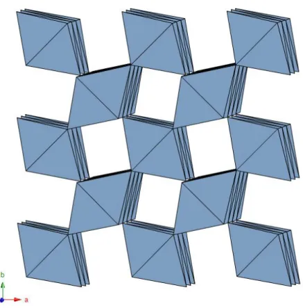
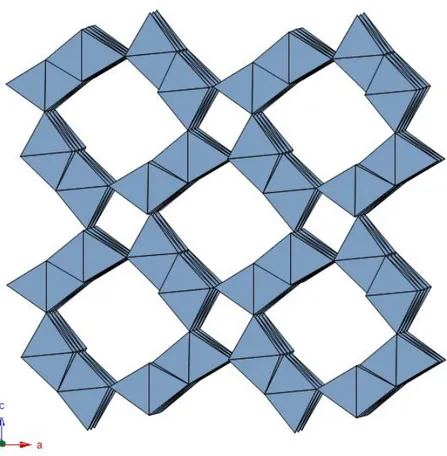
2 × 2 tunnels - The 2 × 2 tunnel structure is the most common and it is characteristic of many mineral species (so many to establish a mineral supergroup) and synthetic compounds, either manganese or titanium oxides. The framework is characterized by double chains of edge-sharing [Mn4+O6] or [Ti4+O6] octahedra, linked to form tunnels with square cross section, two octhaedra wide (Fig. 1.10).
Fig. 1.10 - Structural framework of the 2 × 2 tunnel structures as seen along c.
These tunnels are large enough to host mono- or divalent cations, (e.g., Ba2+, K+, Na+, etc.), and in some case water molecules. The positive charge associated with the tunnel cations is balanced by substitution of some of the Mn4+ or Ti4+ by lower valence cations (e.g., Mn3+, Fe3+, Fe2+, Zn2+, V3+, Cr3+, Al3+).
The ideal topological symmetry of the 2 × 2 tunnel oxides is tetragonal, space group
I4/m (a ≈ 10.0, c ≈ 2.9 Å), but in some cases structural refinements have been carried
out in monoclinic (pseudo-tetragonal) space groups, such as I2/m or P21/n (with the a and c axes slightly different between each other, and the β angle slightly greater than 90°) because of minor distortions of the framework and/or ordering of cations and vacancies along the tunnels. Moreover structures with multiple c unit cell parameters or incommensurate structures may occur.
substitutions within the octahedral framework. In fact, besides the manganate and titanate minerals, a lot of chemically distinct synthetic compounds are known to assume this framework topology.
Here we present a short account of some important synthetic compounds with the same structure topology (the description of the known minerals displaying the 2 x 2 tunnel structure will be given in Chap. II).
Bayer & Hoffman (1996) synthesized several titanium oxides with the general formula A2(Ti4+6M3+2)O16 (where A = K, Rb and M3+ = Al, Ti, Cr, Fe, Ga) or A2(Ti4+7M2+)O16 (where A = K, Rb and M2+ = Mg, Co, Ni, Cu, Zn), and this demonstrates the great tolerance for substitutions in the octahedral framework. Dryden & Wadsley (1958) prepared a series of oriented aggregates of the non-stoichiometric phase Bax(Ti8-xMgx)O16 (with 1.14 > x > 0.67). The results of a solid-state preparation of a synthetics hollandite phase with chemical formula BaxAl2xTi8-2xO16 showed a large range of x, from 0.3 to 1.2 (Sinclair et
al., 1980).
Ringwood et al. (1967a) described a synthetic potassium feldspar KAlSi3O8 that undergoes a polymorphic transition at 9 GPa and 900°C into the hollandite-type structure (a phase with octahedrally coordinated Si4+). This could represent one of the major phase in the Earth mantle. Moreover, a number of minerals with Si and Ge as octahedral cations (KAlSi3O8, KAlGe3O8, NaAlGe3O8, RbAlGe3O8) assume the hollandite-type framework under high pressure conditions (Ringwood et al., 1967b).
The sodium analougue of hollandite-type KAlSi3O8 has been recently discovered in shock melt veins in the L6-chondritic meteorite Sixiangkou and in veins in other shocked L- and H- chondritich meteorites. NaAlSi3O8 with the structure of hollandite minerals was approved as a new mineral species with the name lingunite (Liu, 2006).
Finally, single crystals of plumbous hollandite-type structure with composition Pb0.8Al1.6Si2.4O8 , as well as (Ca0.5Mg0.5)Al2Si2O8, have been synthesized at very high pressure and temperature (16.5 GPa and 1450 °C) (Downs et al., 1995; Madon et al., 1989). The latter phase may represent a possible host of calcium and aluminum in the lower mantle.
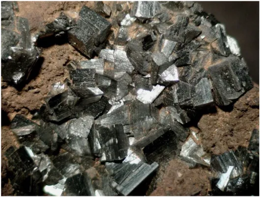
Hollandite-type minerals commonly occur as intergrowths and, in some cases, grade from one to another along the same crystal. They can be major phases in the oxidized zone of Mn deposit and important ores (Post, 1999). They typically are found as fibrous and tabular crystals or in compact botroyoidal masses. Less commonly, hollandite-type minerals occur as prismatic crystals in hydrothermal vein deposits (Fig. 1.11).
Fig. 1.11 - Hollandite tabular crystal in quatrzitic vein. Vagli, Apuan Alps, Italy. ©Biagioni
2 × 3 tunnels - The 2 × 3 tunnel is characteristic of romanèchite, Ba(Mn4+,Mn3+)5O10·H2O. The romanèchite structure is built up by double and triple chains of edge-sharing MnO6 octahedra that link to each other to form large tunnels with rectangular cross section, two by three octahedra wide (Fig. 1.12).
Fig. 1.12 - Romanèchite 2 × 3 structural framework as seen along b.
Romanèchite was often referred to as psilomelane (Wadsley, 1953), a name now discredited, which in the past has been used for a mixture of poorly defined hard black manganese oxides.
The structure of romanèchite was first solved by Wadsley (1953); it crystallizes in the monoclinic system, space group C2/m, with a = 13.85, b = 2.88, c = 9.56 and β = 92.5°. The tunnels are occupied by a double row of Ba ions (and minor amount of other cations such as Na+, K+, Sr2+, etc.) and water molecules (ratio Ba:H2O ≈ 1:2); it is likely that each tunnel contains and ordered sequence of barium cations and water molecules, however the long-range order is lost (Wadsley, 1953). The charge balance is achieved by substitution of Mn4+ by lower valence cations (mainly Mn3+) within the
octahedra. Single crystal X-ray refinement indicates that Mn3+ concentrates on the octahedral sites placed at the edges of the triple chain (Post, 1999).
The structure of romanèchite was subsequently re-determined by Turner and Post (1988) which found a supercell with a 3 × b unit cell parameter (i.e., the tunnel axis), resulting from ordering of Ba and H2O along the tunnel. In fact, they observed a characteristic sharpness of the superstructure reflections along b, which may indicate that Ba2+ and H2O are well ordered within individual tunnels (short-range ordering). More recently, a compound topological related to romanèchite with Na+H2O within the tunnels, with composition (Na, H2O)(Mn4+,Mn3+)12O24 was synthesized by Shen et al. (2004). Moreover, it has been observed that this 2 × 3 Na-tunnel structure is stable below 550 °C and transforms into “hausmannite” at higher temperature.
Romanèchite typically occurs as botroyoidal masses in oxidized zone of Mn-rich deposits (Fig. 1.13). Cross section of botroyoidal samples usually show very fine concentric layering (Fig. 1.13, region within the red box); electron microprobe analysis reveals minor fluctuations in composition among the different layers, mostly in concentration of Ba and minor amount of Na, K, Ca and Sr (Post, 1999).
Fig. 1.13 - Romanèchite in botroyoidal aggregate. The red box indicates the layering. Ober-Kainsbach, Reichelsheim, Odenwald, Hesse, Germany. ©Christian Bracke
HRTEM studies have shown that romanèchite and hollandite commonly intergrow on a very fine scale, and are interconnected via the common double octahedral chain. Moreover, some unusual insulated tunnels (2 × 4 and 2 × 7) were also observed (Turner & Buseck, 1979).
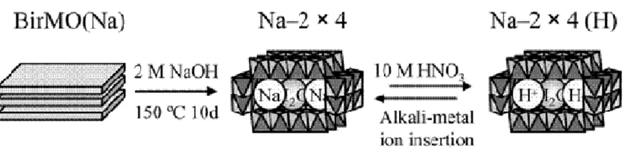
2 × 4 and 2 × 5 tunnels – No natural specimens have been found with 2 × 4 or 2 × 5 framework structure, nevertheless several synthetic compounds have been prepared. Sodium manganese oxides [Na0.33(Mn4+, Mn3+)O2·xH2O] with 2 × 4 tunnels were hydrothermally synthesized from Na-birnessite [Na0.5(Mn4+,Mn3+)2O4·1.5H2O] (Fig. 1.14) (Liu & Ooi, 2003). The authors showed that a number of alkali ions as well as water molecules could be inserted into the tunnel sites in the place of sodium. The tunnel exchange capability increases in the order Cs+ < Li+ < Na+ < K+ ≈ Rb+. Xia et al. (2001)
synthesized the same product and also refined the structure as monoclinic C2/m, a = 14.435, b = 2.849, c = 23.976 and β = 98.18°.
Fig. 1.14 - Synthesis process of 2 × 4 tunnel from Na-birnessite. AfterLiu & Ooi, (2003)
Synthetic Rb0.25(Mn4+,Mn3+)O2 with 2 × 4 framework and Rb0.27(Mn4+,Mn3+)O2 based upon 2 × 5 tunnels has been prepared by Rziha et al. (1996) and Tamada and Yamamoto (1986), respectively.
3 × 3 tunnels - The 3 × 3 structural framework is adopted by todorokite, an hydrated Na-, Ca-Na-, Mg-bearing manganese oxide [(NaNa-,Ca)(Mn4+,Mg2+)6O12·5H2O (Post et al., 2003b)]. The crystal structure of todorokite has been a subject of interest and speculation for several years. Much of this attention comes from its important role as one of the major minerals in the oxidized zones of many Mn deposits and from the capability to incorporate metals in its structure.
Unfortunately, todorokite usually occurs as poorly crystalline masses, and to date no crystals have been found that are suitable for single-crystal X-ray diffraction. Moreover, at most occurrences todorokite assumes the form of platy or fibrous crystals (Fig. 1.15), supporting a long-lasting controversy about its tunnel- or layer-type structure (Burns & Burns (1977); Potter & Rossman (1979); Turner & Buseck (1981).
Fig. 1.15 - Todorokite fibrous crystals. Punta del Aguila, Canary Islands, Spain. ©Volker Betz
Burns & Burns (1977), on the basis of electron-diffraction data and the commonly fibrous habit, proposed a tunnel structure similar to those of romanèchite and hollandite. On the other hand, Potter and Rossman (1979) supported the hypothesis of a layered structure analogue to that of birnessite, by an infrared-spectroscopy study on a birnessite-rich alluvial deposit of manganese oxides. Besides, Giovanoli & Bürki (1975) considered todorokite not a valid species but merely a mixture of buserite (Na4Mn14O27·21H2O) and/or birnessite and manganite.
Finally, Turner and Buseck (1981), confirmed the tunnel model proposed by Burns & Burns (1977), today well accepted, on the basis of accurate HRTEM studies. The HRTEM images revealed that todorokite consists predominantly of triple chains of edge-sharing MnO6 octahedra which share corners to form large tunnels with square cross sections three octahedra wide (Fig. 1.16).
Fig. 1.16 - Polyhedral representation of the crystal structure of todorokite as seen along b.
HRTEM images also showed that, at the atomic scale, todorokite may produce intergrowths with larger tunnels, measuring 3 × 4, 3 × 5, 3 × 6, and 3 × 7, up to 3 × 9 octahedra in cross section (Chukhrov et al. 1980, 1985; Turner & Buseck, 1981). Usually, such tunnels are isolated within the dominant 3 × 3 topology and the faulted sequences developed along one direction only, whereas in the perpendicular direction the walls are invariably 3 octahedra wide.
Finally, the crystal structure of todorokite was solved in the space group P2/m, a = 9.764, b = 2.841, c = 9.551 Å and β = 94.06°, using Rietveld method and powder X-ray diffraction data (Post & Bish, 1988). A further refinement was performed by Post et al. (2003b), by synchrotron powder X-ray diffraction data, which, besides confirming the model proposed by Post & Bish (1988), also led to observe the dehydration of todorokite under different temperature conditions (from 100 to 820 K). At 450 K, todorokite starts to break down and fully decomposes at 620 K, transforming into
Mn3+ and Mn2+ impelled a breakdown of the octahedral framework and the subsequent release of the tunnel H2O.
Chemical analyses show a wide range of tunnel compositions (Ostwald, 1986), and samples of todorokite from ocean nodules contain significant amount of Ni, Co and Cu (Burns & Burns, 1977).
Todorokite typically occurs in Mn deposits as an alteration product of primary ores such as braunite [Mn6(SiO4)O8]. The mineral also seems to be an important phase in Mn desert varnish in arid and semi-arid regions, dendrites within and on the surface of rocks, and deposits within the rivers (Potter & Rossman, 1979). In the ocean nodules it seems that todorokite arises from biological processes, where spores of a marine bacterium are able to oxidize Mn (Mandernack et al., 1995).
Several syntheses of todorokite have been performed by Golden et al. (1986) who prepared a Mg-todorokite starting from Na-birnessite in which Na was exchanged with Mg to obtain Mg-birnessite. Moreover, Ca-birnessite and Ni-birnessite, when autoclaved under conditions similar to those for Mg-birnessite, assume the todorokite structure. Todorokite was also synthesized by autoclaving layer-structure manganese oxides under markedly alkaline conditions (Shen et al., 1993).
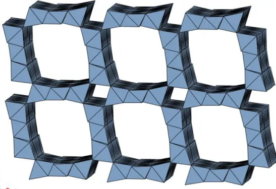
3 × 4 tunnels - The 3 × 4 framework is the largest tunnel structure so far reported in natural and synthetic Mn and Ti oxides. This structural framework is characteristic of woodruffite, an hydrated oxide of Mn and Zn with formula [Zn(Mn4+,Mn3+)5O10·3.5H2O] and consists of tunnels 3 and 4 octahedra wide (Fig. 1.17).
Woodruffite was first described from oxidized zinc ores of Sterling Hill, NJ, USA (Frondel, 1953) and since its X-ray powder diffraction pattern resembled that produced by todorokite, woodruffite was initially assumed to be a Zn-rich variety of that mineral. Later, other occurrences of needle-like crystals of woodruffite were discovered in an oxidized ore body near Mapimi, Durango, Mexico. The diffraction pattern was different from that of todorokite and also HRTEM images confirmed an opening of 3 × 4
octahedra units (Post et al., 2003a), offering a prototype for a new class of OMS materials.
Chemically, the major framework and tunnel cations in woodruffite are Mn and Zn, respectively, with Na, K, Ba, Mg, Si, Al and Fe present in amounts less than 1% and Ca, Sr, Co, Ni, Sn, Cr, Mo, V and Ti present in trace amounts.
Fig. 1.17 - Structural framework of woodruffite as seen along b.
The thermal stability of woodruffite is comparable to that of todorokite. The structure breaks down at about 570 K. The collapse of the structure is triggered by the loss of O atoms from the octahedral framework and the consequent reduction of Mn (Post et al., 2003a), eventually leading to the formation of hausmannite.
This mechanism suggests that a strategy for preparing more thermally stable woodruffite-like phase (as well as todorokite) should focus on altering the framework, rather than the tunnel, composition, perhaps introducing cations with less variation in
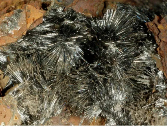
Usually woodruffite occurs as masses and crusts with a botryoidal surface and a coarsely layered internal structure; more rarely as tufts of acicular crystal (Fig. 1.18).
Fig. - 1.18 Needle-like crystals of woodruffite. Carlés Mine, Asturias, Spain. ©Enrico Bonacina
1.2 Ramsdellite: polysomatic issue
Although ramsdellite is considered a member of the tunnel oxides, in strict polysomatic terms this is wrong. As widely described above, tunnel oxides are characterized by two sets of walls which develop in mutually orthogonal direction. This is not the case of ramsdellite, where the ribbons (with width corresponding to two octahedra wide) are parallel (see Fig. 1.5). This gives rise to a tunnel structure as well, however, the small 1 × 1 tunnels found in all other tunnel oxides of the polysomatic family are here lacking (Pasero, 2005). Therefore, the notation “1 × 2” for ramsdellite refers to the dimensions of the tunnels and not to the width of the walls.
1.3 Structural Details
The ideal topological symmetry of the framework of the tunnel oxides is tetragonal or orthorhombic, but often a lowering of the symmetry is observed. The causes of this are probably related to the minor distortion of the framework (i.e. the octahedral distortion) and/or to the ordered distribution of the cations inside the tunnels.
1.3.1 Octahedral distortion
Octahedral distortions commonly occur in tunnel oxides minerals, and often are related to the increase of the structural complexity. Minimum distortion is indeed characteristic of structures with 1 × 1 tunnels (i.e. pyrolusite), whereas the distortion increases for structures with larger tunnels.
This can be related to the characteristic substitution M4+ = M3+ + A+ and/or M4+ = 2M3+ + A2+, that is typical of the larger tunnel phases. The distortion is more evident when the dominant trivalent cation is Mn3+, since it displays the characteristic Jahn-Teller effect. The Jahn-Teller distortion normally leads to an elongation of the bonds relative to two out of the six ligands, resulting in a square, 4+2 coordination, but occasionally two out of the six ligands are shortened, resulting in a linear, 2+4 coordination (the Jahn–Teller theorem does not predict the direction of the distortion, only the presence of an unstable geometry) (Fig. 1.19). When such distortion occurs in tunnel oxides minerals, it causes a general lowering of the symmetry from tetragonal to monoclinic.
Fig. 1.19 - Jahn-Teller effect along z axis.
Another reason of the distortion is probably related to the dimensions of the octahedral cation itself. Sinclair et al. (1980) proposed that as the M cations get larger, the M-O octahedra must distort, causing a lowering of symmetry. Thus, compounds with smaller M cations and, consequently, smaller unit cells, should be tetragonal, whereas those with larger unit cells should be monoclinic.
In fact, through a review of several synthetic compounds with hollandite-type structure (2 × 2), they observed that the substitution of M4+ octahedral cations by lower valence cations (M3+) with smaller size, such as Al3+, leads to smaller cells (V = 236.3 Å3, Reid & Ringwood, 1969) respect to that normally observed in hollandite-type compounds (V ≈ 280 Å3, Post et al., 1982, BystrÖm & BystrÖm, 1950). Conversely, the substitution with cations with larger ionic radii, such as Ga3+, gives rise to greater unit cells (V = 298.9 Å3; Cadèe & Verschoor, 1978) and to a concurrent lowering of symmetry.
Thus, it seems that the symmetry change is more likely to occur between volume values between 290 and 300 Å3.
It must be noted, however, that Post et al. (1982), refining the structure of specimens of hollandite s.s. [Ba(Mn4+,Mn3+)8O16], cryptomelane [K(Mn4+,Mn3+)8O16] and priderite [K(Ti4+Fe3+)8O16], observed that the larger root mean square displacements of the atom positions in the octahedral site, with respect to an ideal octahedron, was for priderite. If these displacements are considered to be a further measure of the degree of distortion, then the priderite octahedra are more distorted than those of hollandite and cryptomelane. However, it has already been pointed out that priderite has a tetragonal unit cell, while hollandite and cryptomelane are monoclinic.
Therefore, it seem that the monoclinic distortion of 2 × 2 tunnel structures cannot result solely from the distortion of M-O octahedra, but also from the dimension of the tunnel cations.
The following picture indicates the displacement of the refined atom positions for monoclinic hollandite s.s. (Post et al., 1982). The length of the arrows are proportional to the magnitude of the displacement. The graphic highlights that the monoclinic distortion is due to a twisting of the M-O octahedra around an axis parallel to b (Fig. 1.20).
Fig. 1.20 - Monoclinic hollandite unit cell as seen along b. Arrows indicate the direction and their length the magnitude of the displacement of atoms positions from those in an ideal tetragonal unit cell. After Post et al. (1982)
This twisting produces a slight decrease of the volume of the tunnel and consequently a structural distortion. This mechanism is similar to the octahedral tilt or twist of compounds with perovskite-like structure (Fig. 1.21). Such a distortion occurs when the central cation is too small with respect to the ideal dimensions of the cavity in which it must be accommodated.
Fig. 1.21 - Octahedral tilting in perovskite.
The degree of distortion in perovskite increases as the ionic radius of the cation in the cavity decreases with respect to that of octahedral cations.
To verify whether the twisting in the 2 × 2 tunnel structure is really similar to that of perovskite-like compounds, Post et al. (1982) plotted the average ionic radii of A-cation
vs. the average ionic radii of M-cation for a series of hollandite s. l. compounds reported
Fig. 1.22 - rA vs. rM for hollandite compounds reported in literature. Filled circle represent tetragonal
frameworks and squares monoclinic frameworks. The dashed line corresponds to rM/rA = 0.48. After Post
et al. (1982).
In general, compounds with monoclinic structure are placed in the lower right part of the diagram, corresponding to “hollandites” with small A cations and relatively large B cations, and compounds with tetragonal structure are placed in the upper left part of the diagram, corresponding to “hollandites” with large A cations and relatively small B cations.
Thus, it seems that if the A cation is too small for the tunnel, the M-O octahedral wall is tilted so as to decrease the volume of the tunnel and to adapt it to the hosted cation, and a monoclinic framework results.
The tetragonal form is separated from the monoclinic one by a dashed line that indicates a rM/rA = 0.48 (see Fig. 1.22). Hence, hollandite compounds with rM/rA < 0.48 are tetragonal and those with rM/rA > 0.48 are monoclinic.
As expected, the β angle for the monoclinic hollandite examined increase as the rM/rA ratio get larger, and leads to the increase of the distortion.
Although detailed studies like the one mentioned above on the structural distortion of larger tunnel such as 2 × 3, 3 × 3 and 3 × 4 are missing, it is easy to guess as these structures undergo a similar type of distortion. In fact, romanèchite, todorokite and woodruffite are normally found with monoclinic symmetry, even if their ideal topological symmetry is tetragonal or orthorhombic.
1.3.2 Cations distribution in 2 x 2 tunnels
The lowering of symmetry may be also related to the ordering of cations along the tunnel.
As it is already known, not all the tunnel oxides are able to incorporate cations inside their cavities, because some of these circumscribe an interstitial space too small (e.g. pyrolusite, 1 × 1, and ramsdellite, 1 × 2, although the latter seems able to host minor amount of water).
Conversely, more open frameworks, such as 2 × 2, 2 × 3, 3 × 3, etc., may host several species of mono- and divalent A cations (with A = Na+, K+, Rb+, Ba2+, Pb2+, etc. ) as well as water molecules.
The incorporation of cations and/or water molecules often leads to a lowering of symmetry as a consequence of the ordering of these host species along the tunnels. The position and the site occupancy within the tunnels is one of the most interesting aspects of the tunnel oxide minerals.
perpendicular to the axis, inversion center); it often happens that cations are displaced off the special positions due to the different ionic radius as well as to the local interactions with the oxygen atoms of the framework.
Another reason of the displacement is related to the impossibility of placing cations on neighbor, translationally related and fully occupied sites along the tunnel axis. In fact the translation is less than 3 Å in the 2 × 2 framework, i.e. shorter than the minimum A – A distance electrostatically acceptable; therefore, partial occupancy at these sites is required, as well as some kind of ordering of cations and vacancies along the tunnels, which may give rise to structures with multiple b or c unit cell parameters or to incommensurate structures.
In the ideal 2 × 2 tunnel structure (I4/m), tunnel cations lying at (0,0,0) fit into cavities that are formed by eight oxygen atoms, four placed at z = ½ and four at z = -½, at the corners of a distorted square prism, with A – O distances in the range of 2.8 – 3.0 Å. These A cations can be displaced off the special position along the tunnel toward four of the coordinating O atoms. Moreover, four additional oxygen atoms at distance of ca. 3.5 Å, and at the same z level of the A cation, can be considered as additional capping anions, one for each of the four vertical faces of the distorted prism mentioned above (Pasero, 2005) (Fig. 1.23).
Fig. 1.23 - Two tunnel site views in the ideal 2 × 2 tunnel structure. The tunnel cation (red) is ideally coordinate by 12 oxygens (green). After Pasero (2005).
Many studies on 2 × 2 tunnel oxides show the displacement of A cation off the special position. Post et al. (1982), in their study concerning the symmetry and cation displacements in hollandite s.s. [Ba0.75Pb0.16Na0.10K0.04(Mn,Fe,Al)8O16], cryptomelane [K0.94Na0.25Sr0.13Ba0.10(Mn,Fe,Al)8O16], and priderite [K0.90Ba0.35(Ti, Fe, Mg)8O16], observed that some or all of the tunnel cations are displaced off the special position. In hollandite and cryptomelane, the Ba2+ and K+ lies at (0,0,0) whereas the Pb2+, Sr2+ and Na+ are displaced off that site. In priderite both the Ba2+ and K+ are displaced. These displacements may result in more energetically stable coordination polyhedra for the tunnel cations, in which the A-O distances better fit the expected values on the basis of the ideal ionic radii.
K+ in cryptomelane lies at (0,0,0), at a distance of ca. 2.88 Å from the eight coordinating atoms. These contact distances are nearly those predicted using the ionic radii of Shannon (1976). Therefore, the K+ in cryptomelane is not displaced because its bond distances with coordinating anions are within expected values.
Sr2+ and Na+, instead, are smaller than K+ and form shorter Sr2+- O and Na+ - O connections. Thus, if both these cations were placed at (0,0,0), this would result in unacceptable bond distances with oxygen atoms. The Sr2+ is shifted by ca. 0.60 Å to be at the predicted 2.64 Å bond distance from four of the coordinating O atoms. This correspond to the site observed for Sr in cryptomelane, at (0,0.18,0), resulting in average Sr-O distances of ca. 2.65 Å (Fig. 1.24a).
The difference Fourier synthesis of cryptomelane also shows a maximum of electron density in the tunnel at the center of the small square defined by four O atoms, at (0,0.5,0). The only cation small enough to fit into this site is Na+. The four observed Na+ - O distances of 2.49 Å are between the 2.56 and 2.38 Å values predicted for Na+ in eight- and fourfold coordination respectively (Fig. 1.24b).
Fig. 1. 24 - (a) Sr (light blue) atoms at (0,0.18,0)and K (black) at (0,0,0) and (b) Na (grey) atoms at (0,0.5,0) and K (black) at (0,0,0) in cryptomelane (Post et al., 1982).
In hollandite, the distance from the special position (0,0,0) to the eight coordinating O atoms is 2.89 Å (about the same as in cryptomelane) and this distance is only 0.1 Å longer that the theoretical Ba2+- O distance. The Ba2+ is located exactly at that site in special position (0,0,0) whereas Pb2+ must shift by ca. 0.58 Å, at (0,0.2,0) to form suitable Pb2+- O distance (2.67 Å). This agrees with the subsidiary tunnel site found at (0,0.2,0) in hollandite, where the Pb2+ is at 2.65 Å from four of the neighboring O atoms. Moreover, Post et al. (1982) observed that the anisotropic displacement parameters for both these cations (especially for Pb) show elongation along the tunnel direction, indicating additional positional disorder on these sites (Fig. 1.25)
Fig. 1.25 - Thermal ellipsoid model for hollandite; Pb (dark grey) atoms at (0,0.2,0) and Ba (pink) at (0,0,0). Note that anisotropic displacement parameters for Pb cations show elongation along the tunnel direction. (Post et al., 1982).
In priderite, the ionic radius of Ti4+ (0.745 Å) is larger than that of Mn4+ (0.67 Å); consequently, the framework structure is expanded relative to that of hollandite and cryptomelane (V = 304.94, 280.72, 277.35 Å respectively). In priderite K+, to be at its predicted K+- O distance of 2.88 Å, should occupy a site at (0,0,0.06). Similarly, Ba2+ should occupy a site at (0,0,0.17) to be at a distance of 2.79 Å from the framework oxygen atoms. The experimentally determined positions of the tunnel cations observed by Post et al. (1982) are: barium at (0,0,0.18), and potassium at (0,0,0.03), in fairly good agreement with the expected position.
Fig. 1.26 - Thermal ellipsoid model for priderite; K (black) atoms at (0,0,0.03) and Ba (pink) at (0,0,0.18).
Table 1.2 summarizes the types of tunnel cations, their positions and the refined site occupancies for the three minerals studied by Post et al. (1982).
Tab. 1.2 - Tunnel cation positions and occupancies in hollandite, cryptomelane and priderite (after Post et al., 1982).
Tunnel cation Refined occupancy Tunnel site
hollandite Ba2+ 0.34 (0,0,0) Pb2+ 0.15 (0,0.20,0) Na+ 0.05 (0,0.5,0) K+ 0.02 (0,0,0) cryptomelane K+ 0.65 (0,0,0) Na+ 0.11 (0,0.5,0) Sr2+ 0.08 (0,0.2,0) Ba2+ 0.05 (0,0,0) priderite K+ 0.66 (0,0,0.03) Ba2+ 0.10 (0,0,0.18) Na+ 0.02 (0,0,0.5)
1.3.3 Theoretical occupancy in 2 × 2 tunnels
Another interesting aspect of the 2 x 2 tunnel structures is the variable extra-framework cation occupancy on the basis of the dimensions and oxidation state of atomic species hosted.
Post & Bish (1989), e.g., observe that coronadite (Pb2+ as tunnel cation) is able to accommodate more cations in the tunnel than hollandite s.s., which has Ba2+ as the predominant tunnel cation. They studied two samples of coronadite from Morocco
[Pb1.06Ba0.10(Mn4+,Mn3+)7.7V0.20Al0.08O16] and Australia
[Pb1.40(Mn4+,Mn3+)7.9Al0.05Zn0.05O16·1.55H2O]. The refined Pb position is displaced approximately 0.60 Å along the tunnels from the special position at (0,0,0) which is consistent with the previously observed displacements of other hollandites s.l. (Post et
al., 1982). In both samples the coordinates of the sites are ca. (0,0.22,0). Chemical
analyses of coronadite from Morocco and Australia showed 1.0 to 1.4 tunnel cations per formula unit (the tunnel sites are 1/2 to ca. 2/3 filled), whereas the mineral hollandite typically has less than 1.0 tunnel cation per unit cell. When hollandite s.l. contains minor amounts of univalent tunnel cations, or of Pb2+, then the tunnel occupancy might reach 1.1 - 1.2 cations per unit cell. The maximum occupancy of the tunnel sites is probably limited by the size and charge of the cations. Thus hollandite-type structure can accommodate smaller and univalent cations more easily than larger and divalent cations.
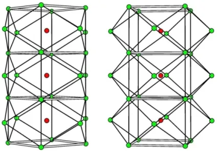
Indeed, it has been often observed that K+ and Na+ in 2 × 2 tunnel oxides can reach 1.3 to 1.5 atoms per unit cell (Post & Bish, 1989). In the case of hollandite s.s. [Ba(Mn4+,Mn3+)8O16], charge repulsion prevents Ba ions from occupying neighboring unit cells along a given tunnel (Fig. 1.27a). In coronadite, the smaller Pb2+ cations can be displaced off the special position, thus increasing the distance between cation sites in a given tunnel (Fig. 1.27b). As a result, Pb cations can fill ⅔ of the tunnel sites (1.33 apfu).
Fig. 1.27 - Representation of three unit cells along the tunnels in hollandite s.s. (a) and in coronadite (b), showing distances between adjacent sites. The increased interaction distance in (b) minimizes repulsion forces and allow up to ⅔ filled sites per unit cell, compared with only ½ of sites in hollandite s.s. (a). The filled circle represent filled cationic sites, and the X represent vacancies. After Post & Bish (1989)
This occupation scheme and the resulting tunnel cations ordering seems to be a common feature in the 2 × 2 tunnel oxides. The sequence of sites slightly below and slightly above the special position at (0,0,0) togheter with a vacancy have been observed in almost all 2 × 2 structures.
Biagioni et al. (2009), in their refinement of the structure of ankangite, (Ba1.16Ti5.68V2.32)O16, observed the presence of a satellite Ba2 site at (0,0,0.13) slightly displaced from Ba1 site at the special position (0,0,0).
They suggested the same tunnel cation distribution described above: one in which every second Ba1 site is empty (total occupancy of 50%) (Fig. 1.28 left side), the other characterized by the sequence Ba2b-Ba2a-vacancy with a total occupancy of 66% (⅔ of the tunnel sites) (Fig. 1.28 right side).
Fig. 1.28 - Tunnel cations ordering in ankangite (Ba1.16Ti5.68V2.32)O16. The filled circles represent cationic
site at (0,0,0), and the empty circles represent the cationic sites at (0,0,0.13) AfterBiagioni et al. (2009)
One dimensional incommensurate modulation of ankangite was observed by Shi et al. (1991) who proposed a supercell 14 times longer than the basic 2.9 Å subcell (c translation).
Even synthetic 2x2 tunnel oxide compounds show this characteristic displacement and ordering of the tunnel cation.
Sinclair et al. (1980) synthesized a compound with ideal formula BaTi6Al2O16, the most abundant phase in Synroc®, a synthetic rock designed and employed for nuclear-waste immobilization (Ringwood, 1979).
These authors initially hypothesized that the Ba cation lied on the special position (0,0,½), using the atomic coordinates from BystrÖm & BystrÖm (1950).
Subsequently they showed that Ba atoms were incorrectly located at this site. The correct position for these cations was at (0,0,0.38). This positional shift was also observed by Cadèe & Verschoor (1978) who reported a displacement from the special position of 0.52 Å for Ba2+ in a synthetic compound with general formula BaxSn4-2xCr2xO18. Even Beyeler (1976) proposed a shift from the (0,0,0.5) position for K+ in K1.54Ti7.23Mg0.77O16.
Anyhow, all the above-cited authors proposed the same tunnel cation scheme distribution: if the occupancy of Ba2+ is ca. 50%, then the A site should be occupied every second unit cell (Fig. 1.29a). At higher Ba2+ concentrations adjacent cells can be occupied, too, up to a max occupancy of 2/3 (Fig. 1.29b)
Fig. 1.29 - Schematic diagram of tunnels showing six unit cell parallel to c (a) at 50% Ba occupancy, (b) at higher occupancies. The filled circle represent filled cationic site, and the empty circles represent vacancies.After Sinclair et al. (1980)
Thus, if Ba occupancy is more than 50 % and Ba atom occupy R1 position (see Fig. 1.29b), then the probability to find it at Q1 is equal to zero. The probability of finding Ba in both
cations occupy sites R1 and Q2 is the most favoured when adjacent cells have to be occupied (R1 - Q2 = 3.62 Å).
On the other hand, Endo et al. (1976) did not observe any displacement for K+ in a monoclinic hollandite structure (a = 13.820, b = 2.941, c = 9.772 Å and β = 135°) of the synthetic phase K2Cr8O16, which has K+-O contact distances to the eight coordinating O atoms of 2.90 Å, very close to the predicted value of 2.88 Å.
1.3.4 Cations distribution in larger tunnels
Structures with larger tunnels can host more complex sets of cations as well as water molecules. In romanèchite [Ba(Mn4+,Mn3+)5O10·H2O, 2 × 3 framework, A2/m, a = 9.56, b = 2.88, c = 13.85 Å, β = 92,5°] the tunnels are occupied by a double row of Ba2+ ions shifted by ½ along b, and minor amounts of other cation such as Na+, K+, Sr2+, etc., and H2O (Wadsley, 1953) (Fig 1.30).
Fig. 1.30 - Projection down b of the romanèchite structure. The tunnels host two equivalent cation sites, occupied by Ba and/or H2O.
Each tunnel cation is located at the center of a polyhedron formed by ten oxygen atoms. These polyhedra are arranged into rows running within the tunnels and are linked by shared edges (Fig. 1.31a).
Fig. 1.31 - (a) The staggered string of polyhedra. The shared edge link two water molecules. (b) Ba and H2O atoms ordering as seen along c.
The shared edge corresponds to the linkage (Ba, H2O) – (Ba, H2O). Since two adjacent Ba cations would tend to repel each other, it is unlikely that these occupy the sites along the shared edge, which is equal in lenght to the diameter of Ba ions. For this reason, the
(b) (a)
disposition of the row would be (being the ratio Ba: H2O ≈ 1:2) (Fig. 1.31b) with Ba as the central coordinating cation of the polyedra, and H2O in common to each unit of the staggered string.
More recently, Turner & Post (1988) reported a supercell of romanèchite with a triple b tunnel axis (Fig. 1.32).
Fig. 1.32 - Precession diffraction patterns parallel to b* showing tripling of romanèchite subcell.
The refinement shows and confirms that the superstructure reflections arise from the ordering of Ba and H2O in the tunnel direction. Conversely, the streaking of the supercell reflections along the direction normal to b indicates disorder of Ba and H2O between tunnels (Fig. 1.33).
Fig. 1.33 - Patterns at 90° respect to b* showing that the spots are modulated streaks.
In todorokite [(Na,Ca,K)(Mn4+, Mg)6O12·5H2O, 3 × 3 framework, P2/m, a = 9.77, b = 2.85,
c = 9.56 Å, β = 94,47°] there are three independent sites within the tunnels,
predominantly occupied by water molecules (Post & Bish, 1988; Post et al. 2003b). Fourier-difference maps and subsequent refinement show a major tunnel site at (0.36, 0, 0.35) and a smaller more diffuse area of electron density near (0.69,0.5,0.38) and (0.5,0.5,0.5) (Fig. 1.34).
Structure-energy calculation revealed that probably the first two sites are occupied by H2O molecules, and the third one by the tunnel cations (Na, Ca, K) which are octahedrally coordinated by molecules occupying the other two tunnel positions (Post & Bish, 1988).
Anyway the difference maps indicate considerable positional disorder on the tunnel sites, probably caused by various tunnel contents and configurations of lower-valence octahedral cations in different unit cell. The [Mn4+O6] octahedra at the edges of the triple chains have larger mean Mn-O distances and probably accommodate the larger cations found in todorokite, e.g., Mg2+, Mn3+, Cu2+, Ni2+, etc.
Fig. 1.34 - Projection of todorokite structure along b. The black atoms represent H2O at y = 0.5, the red
ones H2O at y = 0 and the blue one to the cations position.
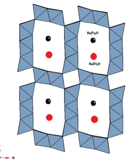
In woodruffite [Zn2+0.2(Mn4+,Mn3+)O2·0.7H2O, 3 × 4 framework, C2/m, a = 24.76, b = 2.85, c = 9.54 Å, β = 93,77°] the tunnels contain four independent H2O molecules and two Zn cations: one of them is located at about (0.3,-0.4,0.5), the other one, quite oddly, at (0,0,0) within the small 1 × 1 tunnels (Fig. 1.35) (Post et al. 2003a). The former are distributed over two parallel rows of sites near the center of the tunnels. The chemical analyses and structural refinement revealed that Zn sites are about ⅔ filled and weak rows of superstructure reflections suggested some type of cation-vacancy ordering among neighbor cells (Post et al. 2003a).
The occurrence of a partially occupied cation sites within the 1 × 1 tunnels in wodruffite represents a somewhat unique situation. In fact, as said above, those tunnels are not expected to host any cation, due to their reduced diameter. In woodruffite, the incorporation of minor Zn within those sites could be related to cation deficiencies in the neighbor octahedral sites.
Fig. 1.35 - Projection of woodruffite structure viewed along b.
In fact, that level of occupancy indicates an ordering scheme in a given column of Zn cations with every third tunnel site vacant. In this way Zn cations increase their separation (from 2.85 to about 3.65 Å) reducing the Zn-Zn repulsion. A very similar splitting has been observed for the Pb cation site in coronadite, mentioned above. Lastly, in synthetic 2 × 4 and 2 × 5 compounds, the large cavities are filled by Rb+ cations distributed over four partially occupied independent sites and variably coordinated by 8 to 10 oxygen atoms (Rhiza et al., 1996; Tamada & Yamamoto, 1986)
Chapter II: Minerals of the hollandite supergroup
2.1 Introduction
Among the tunnel oxides phases, minerals of the hollandite supergroup are surely the most important and common, because of their technological significance ant their common occurrence in many geological settings. As already described, minerals of the hollandite supergroup are structurally characterized by octahedral walls (2 × 2 octahedra wide) cross-linked to each other to build up a tunnel structure. On chemical grounds, the hollandite supergroup can be divided into two groups depending on the dominant tetravalent cation in the octahedral walls: the manganate group (with Mn4+ as octahedral cation) and the titanate group (with Ti4+ as octahedral cation). Moreover, the minerals belonging to these groups differ to each other depending on the predominant tunnel cation species: Ba, K, Pb, Sr, etc..
What follows is a chemical and structural description of all the minerals belonging to the hollandite supergroup.
2.2 Manganate group
The best known example among the minerals of the manganate group is hollandite s.s., that can be represented by the simplified chemical formula Ba(Mn4+6Mn3+2)O16, even though wide compositional variability has been reported. The crystal structure of hollandite s.s. was first resolved by BystrÖm and BystrÖm (1950) from Weissenberg photographs. These authors solved and refined the structure in the I4/m space group with cell dimensions: a = 9.96(1), c = 2.86(1) Å. They defined also the atomic position as: - 2a or 2b: 0, 0, 0 or 0, 0, 0.5 where Ba2+ is placed;
- 8h: x, y, 0; -x, -y, 0; -y, x, 0; y, -x, 0 where Mn4+, Mn3+ and the other possible octahedral cations are placed.
assumed that the positions 2a or 2b are filled at the 50% level, and that there was still a possibility of 25% for Ba ions in adjacent position. Noteworthy, they did not record any extra reflections (doubling the c parameters) among the ones defining the 2.86 Å periodicity.
Conversely, Mukherjee (1960) refined two samples of hollandite, both from Kàjilidongri, in the monoclinic space group P21/n, with a doubled b axis: a = 10.02, b = 5.76, c =9.89 Å, β = 90.60° and a = 10.03, b = 5.76, c =9.90 Å, β = 90.70° (the b axis in the monoclinic setting corresponds to the c axis in the tetragonal setting; in both cases it is the direction in which tunnels develop).
A more precise refinement was carried out by Post et al. (1982), who actually showed that the hollandite s.s. structure is monoclinic, space group I2/m, with a = 10.026(3), b = 2.8782(7), c = 9.729(3) Å and β = 91.03°(2). They claimed that the symmetry of hollandite s.s., as well as other hollandite type structure compounds, depends on the ratio of the average ionic radius of the octahedral cations with respect to that of the tunnel cations (see par. 1.3.1, chap. I). In those structures in which the ratio is > 0.48, the volume decreases, the structure deforms and as a result a slight lowering of the symmetry occurs (from tetragonal to monoclinic).
Cryptomelane is analogous to hollandite, from which it differs only for the tunnel cation, namely, K+ instead of Ba2+. Its ideal formula is [K(Mn4+7Mn3+)O16]. The crystal structure of cryptomelane was first solved by Mathieson & Wadsley (1950), who, through Weissenberg photographs, initially found a body-centered tetragonal cell, space group I4/m, a = 9.82, b = 2.86 Å; subsequently they better refined the cell in the monoclinic space group I2/m, a = 9.79, b = 2.88, c = 9.94 Å and β = 90.62°. A more recent refinement was carried out by Post et al. (1982) in the space group I2/m with a = 9.956, b = 2.8705, c = 9.706 Å and β = 90.95°.
Anyhow, the structure of a synthetic compound chemically identical to cryptomelane was refined at room temperature in the tetragonal space group I4/m [a = 9.866(3), c = 2.872(1) Å] (Vicat et al., 1986).