2015
Publication Year
2020-05-18T17:17:46Z
Acceptance in OA@INAF
Alignment and integration of large optical systems based on advanced metrology
Title
Aliverti, Matteo; RIVA, Marco; Moschetti, Manuele; PARIANI, Giorgio; Genoni,
Matteo; et al.
Authors
http://hdl.handle.net/20.500.12386/24946
Handle
MEMORIE DELLA SOCIETA ASTRONOMICA ITALIANA
Journal
86
Number
c
SAIt 2015 Memoriedella
Alignment and integration of large optical
systems based on advanced metrology
M. Aliverti
1,2, M. Riva
1, M. Moschetti
1,2, G. Pariani
1,
M. Genoni
1, and F.M. Zerbi
11 INAF – Osservatorio Astronomico di Brera, Via Emilio Bianchi 46, Merate, Italy
e-mail: [email protected]
2 Politecnico di Milano, Dept. of Mechanical Engineering, Via La Masa 1, Milano, Italy
Abstract. Optical alignment is a key activity in opto-mechanical system Integration. Traditional techniques require adjustable mounting, driven by optical references that al-lows the tuning of the optics position along all 6 Degree of Freedom. Nevertheless, the required flexibility imposes reduced stiffness and consequently less stability of the system. The Observatory of Brera (OAB) started few years ago a research activity focused onto the overcoming of this limits exploiting the high metrology performances of Coordinate Measuring Machines (CMM) with the main objectives of relax the manufacturing toler-ances and maximize mounting stiffness. Through the T-REX grants, OAB acquired all the instrumentation needed for that activity furthermore considering the ESPRESSO project training and testing also oriented to large scale instrumentation like the E-ELT one. We will present in this paper the definition of the VLTs convergence point and the feasibility study of large mirrors alignment done by mechanical measurements methods.
Key words.Laser Tracker – Coordinate Measuring Machines – Alignment – ESPRESSO – MAORY
1. Introduction
Nowadays a large number of high accuracy measurement devices is available on the mar-ket. Unfortunately those instruments are usu-ally dedicated to specific tasks making them difficult to use for the alignment of optome-chanical systems. In recent years there’s been a boost in the development of CMMs, a se-ries of devices capable to calculate the rela-tive position of different points and, as a conse-quence, to calculate the geometrical character-istic of one or more objects. For contact mea-surements the main representatives of this
fam-ily are the articulated arm, the laser tracker (LT) and the cartesian CMM. The articulated arm is a medium to low accuracy passive sys-tem composed by a series of connected bars with 3 to 7 encoders used to calculate the an-gular position of the joints and, then, to re-construct the position of a probe. The LT is a medium accuracy active system that use 2 mo-torized encoders, 2 lasers and a position sens-ing detector to track the position of a Spherical Mounted Retroreflector (SMR) and produce a series of points in a spherical reference system over a large volume. The cartesian CMM, usu-ally simply indicated as CMM, is composed by
Aliverti: Alignment and integration based on advanced metrology 405 a series of three beams orthogonal to each other
with a probe attached to the third one used for high accuracy points acquisition. Even if a large number of different configurations are possible the most common one is the bridge type with a motor for each axis and a triggered contact probe at the end of the vertical one. The motors and the trigger give to the CMM a large advantage in terms of productivity, accu-racy and repeatability with respect to manual systems like LTs and Articulated Arms. The first two systems here presented are already in use in OAB for geometrical acceptance of mechanical parts and for the alignment of me-chanical and optomeme-chanical systems. An ex-ample of this alignment will be presented in the next chapter. After some encouraging re-sults we have decided to investigate the fea-sibility of using a CMM in order to increase the alignment capabilities by directly touching the optical surfaces. The results of those stud-ies and the next foreseen steps will be shown in the further chapter.
2. Mechanical metrology: ESPRESSO Front End main structure
integration
ESPRESSO is the next generation echelle spectrograph to be installed at Paranal’s VLT and that will be characterized by an extreme radial velocity precision (M´egevand et al. 2012). The spectrograph will be placed at the Combined Coud´e Lab and will be fed with the light incoherently coming from the four tele-scopes thanks to the Front End (Riva et al. 2012). In order to define the optical path link-ing each of the 4 Telescope Coud´e Trains to the 6 fibers corresponding to the different modes a reference system with the origin located in the center of the mode selector must be defined and all the mechanical interfaces must be aligned with respect to it. A list of the steps followed to achieve this goal are here briefly summarized.
2.1. Reference system definition
The first part of the alignment consisted in the definition of a starting ESPRESSO refer-ence system. The LT has been placed in the
Combined Coud´e Lab and the center of each circular flange of the 4 coud´e rooms have been acquired. The best fit of those 4 points pro-vided the position of the optical plane (XY). A pin and a spherical joint have been used as ori-gin placing it in an X and Y position roughly defined by Paranal design as the intersection of the 4 coud´e tunnels at an appropriate height (Z0). The projection of the line connecting the origin with the center of UT2 flange onto the optical plane defined the Y axis.
2.2. Ground plates alignment
A virtual hole pattern, aligned with respect to the previously defined reference system has been projected on the floor using the LT. Targets have been glued in the proper posi-tion to guide the drilling of the holes for all the 7 interface plates. After the drilling a spe-cial balancer holding the plates has been placed over the pin and has been aligned in tip tilt and clock using 2 LT markers previously charac-terized with respect to the plates (see Fig. 1 (a)). After the grouting the balancer has been removed and the tip tilt error between the opti-cal plane and the plane defined by the 7 plates has been measured obtaining a tip-tilt value of 34.6asec.
2.3. Main structure and mode selector alignment
The structure with the final interfaces has been placed over the pin and aligned in the correct clock position and finally fixed to the plates. It was necessary to center in X and Y with respect to the structure interfaces and in tip-tilt with respect to the optical plane the mode selector rotary stage, in order to achieve the proper position. The angular alignment has been done comparing the optical plane with the one generated by a full rotation of the table (an extension bar and a retroreflector for the LT were mounted on it). The error obtained, after a proper shimming of the plate under the ro-tary stage, was 2.85asec along the X axis and −0.61asec along the Y axis.
Fig. 1.From left to right: (a) balancer and plates during alignment; (b) detail of the Front End structure with the mode selector and the pentaprism; (c) Front End structure interfaces.
2.4. Coud ´e axis definition
For the definition of the 4 coud´e axis a green laser has been optically aligned along the Z axis. At the end of this phase the beam, com-ing from the ceilcom-ing, can be shined into the 4 tunnels up to the center of the 4 flanges thanks to a pentaprism mounted over the mode selec-tor (see Fig. 1 (b)). To reference this laser with all the other elements previously acquired an SMR has been mounted at the proper height and acquired by the LT. Merging this informa-tion with the ones obtained by the mode selec-tor encoder the definition of the final reference system defined by the laser has been done.
2.5. Front End interfaces acquisition
All the relevant interfaces have been acquired (see Fig. 1 (c)) in order to have all the data needed for the integration of the other Front End subsystems.
3. Mechanical metrology for large optics: MAORY Fore Optics
The use of a CMM instead of manual LT or Measuring Arms will be a strong step forward alignment of large optomechanical elements like the MAORY ones (Diolaiti et al. 2010). This is related to a number of intrinsic charac-teristics of those machines; in particular:
– The Maximum Permissible Error (MPE) is the order of a few micrometers while for the typical manual measuring machine is about one magnitude worse. Moreover
the uncertainty of the measure can be es-timated using different methods (ISO/TS 15530).
– The contact pressure of the probe can be extremely low and repeatable.
– It’s possible to set up the measurement plan with different sampling strategies.
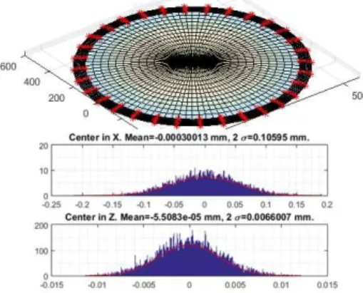
Those characteristics of the machine could al-low for the alignment of the optical elements directly touching and acquiring the optical sur-faces. In order to check its feasibility and to estimate the performance required a software performing a Monte Carlo uncertainty calcu-lation has been implemented. For this kind of analysis a number of factors can influence the results: mechanical characteristics of the ma-chine, feature form error, environmental fac-tors (mainly temperature, temperature distribu-tion and vibradistribu-tions), probe system errors, fea-ture form errors, fitting algorithms used and sampling strategy (Baldwin et al. 2007). In our case we decided to focus the simulations to understand the effect that different sampling strategies and the knowledge of different geo-metrical parameters can have on plane, spheri-cal (as the example shown in Fig. 2) or aspher-ical surfaces reconstruction.
Those analysis showed us that a similar ap-proach can be used and, most important, that when some geometrical parameter is unknown touching the optical surface clear aperture can improve the quality of the measurement. In or-der to verify that this operation won’t effect the quality of the optical element (Meli et al. 2007) a robust and complete damage evalu-ation will be done. This analysis will have to account a large number of situations related to
Aliverti: Alignment and integration based on advanced metrology 407
Fig. 2.An example of sampling strategy simulation (1200mm spherical mirror with known radius).The histograms shows the error in X and Z direction and the 2σ value
the CMM itself see (Hocken et al. 2011) like stylus ball material, probe geometrical prop-erties (mainly due to inertia effects), adhe-sion, dynamic effects (approach speed, mea-surement effects, structural and stylus eigenfre-quencies,...) and travel direction with respect to CMM axes and object surface. Different condi-tions also on the optical element side must be considered. Those are in general related to the substrate and coating materials and to the de-position method. The CMM acquisition of an optical surface for one or more times in a spe-cific condition could cause microscopic dam-ages on the optical surface like scratches, digs, cracks and coating delamination resulting in immediate or over time optical quality degra-dation. This degradation will be quantified and the main parameters will be identified in order
to choose the best strategy for the alignment of both lenses and mirrors.
4. Conclusions
The alignment of mechanical and optomechan-ical systems using contact measurements by different measurement machines like LTs and Articulated Arms has been proven feasible and a successful example of this has been shown. After a preliminary theoretical analysis and different simulations the use of a CMM for the alignment of optical elements could be a big step forward in mechanical alignment mainly due to its higher accuracy and repeatability and the low measurement forces. An extensive test campaign will then be done to validate and im-prove the theoretical model, to choose the best measurement strategy and to optimize the ma-chine configuration.
References
Baldwin, J.M. et al. 2007, Measure, 2, 40 Diolaiti, E., et al. 2010, Proc. SPIE, 7736,
77360R
Hocken, R.J., and Pereira, P.H. 2011, Coordinate measuring machines and systems (CRC Press, Boca Raton, FL)
M´egevand, D., et al. 2012, Proc. SPIE, 8446, 84461R
Meli, F. and K¨ung, A. 2007, Measurement Science and Technology, 18, 496
Riva, M., et al. 2012, Proc. SPIE, 8446, 84469E