978-1-4244-4439-7/09/$25.00 ©2009 IEEE
Giovanni Saggio
(a)(c),, Giuseppe Latessa
(a), Fabio De Santis
(a), Luigi Bianchi
(b)(c)(d), Lucia Rita
Quitadamo
(b), Maria Grazia Marciani
(b)(d), Franco Giannini
(a)(a) Dept. of Electronic Engineering “Tor Vergata” University, 00133 Rome, Italy (b) Dept. of Neuroscience, “Tor Vergata” University, Via Montpellier 1, 00133 Rome, Italy
(c) Centro di Biomedicina Spaziale, Via della Ricerca Scientifica snc, 00133 Rome, Italy (d) Fondazione Santa Lucia IRCCS - Neurofisiopatologia, Via Ardeatina 306, 00179 Rome, Italy
e-mail: [email protected]
Abstract
Human hand and finger movements are of obvious importance. The possibility of recording all fingers joints movements during everyday life is then strategic for medical diagnosis, surgery and post traumatic rehabilitation. A proper presentation of recorded data can be really useful for doctors and therapists to correctly act in the occurrence of peripheral nerve injury, rigidities, camptodactyly (decline in permanent deformity of the interphalangeal junction), orthoses, tenolisi, congenital malformations, trauma, dexterity and/or muscular and/or articulate motility evaluations, thumb atros, syndromes, use of mentors, spasm, use of mechanical supports etc.. According to this context we report a virtual reality implementation on the basis of fingers movements recorded data, suitable for fingers joints movement analysis.
Index Terms— Virtual reality; e-health
1. Introduction
The medical field is becoming the main motivation behind the latest progress in the instrumented glove technology, referring to the reached know-how and applications in measuring joint finger positions and movements. For such a reason it is necessary for engineers and technicians to collaborate with doctors, therapists and surgeons, furnishing to them the easiest way to evaluate collected data purged from unnecessary or ineffective extrapolated values. This is why we report a virtual reality implementation, providing methods and evaluating results for a useful e-health application, since a visual representation can be an important aid in understanding data. Last but not least, virtual reality based technology plays a key role in telemedicine, ranging from remote diagnosis to complex teleinterventions [1].
2. Wearable System
We mean as “instrumented-glove” the ensemble of mechanical and electrical transducers, a support (usually Lycra based), conditioning electronics plus power supply and a transmission system, all useful to measure the 23 degrees of freedom [2] of fingers joints movements.
2. 1 Transducers and support
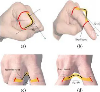
Here we adopted bend sensors as transducers. This is because of their lightness, cheapness and the fact that we experienced a new way of application which, differing from the usual literature way of usage [3, 4, 5], prevents these sensors from being stressed by elongation and torsion forces. In such a way it is potentially avoided the problem that some unwanted forces may prejudice the sensor from returning to its initial state because of its non perfect elasticity, so to lead to a drift in the sensor characteristics during its life of utilization. Moreover, in this way we potentially prevented the “force of the hand grip” from leading to the so defined “source of noise in the sensor output” [6]. We propose to apply the sensors on the glove, in correspondence to the dorsal part of the hand, in a way that, in order to measure flex/extension movements, the sensors themselves assume an arched form when the fingers joints are in flat position, and follow the fingers profiles with closed fist, as figure 1a,1b schematized. The sensor arched form is also utilized for measuring addu/abduction movements as in figure 1c, 1d.
(a) (b)
(c) (d)
Figure 1. Sensors in arched configuration to measure (a)(b) flex/extension and (c)(d) addu/abduction movements. Since overall measurement performances of the bend sensors can be influenced by support onto which they are mounted [7], we preferred to adopt a glove with a reduced degree of elasticity. In such a manner the sensor responses depend for the most part on their arched form and in a minimum way on the change, with joint movements in the inter-distance between sensor ends due to the glove elastic behavior.
2. 2 Conditioning electronics and power supply
Resistance values recorded from the sensors were converted into voltage signals and then fed into two 16 bit TI CD4067B multiplexers, followed by a Microchip MCP3202 A/D converter. A Microchip PIC16F690 microcontroller, which receives data from the A/D converter via SPI protocol, addresses the multiplexers in order to query one sensor a time and finally it furnishes data to a wireless system and then to a personal computer. 5 4 16 -C H A N N EL M U X/ D E M U X 2-CH. MUX/ DEMUX A/D PI C 16 F6 90 16 -C H AN N EL M U X/ D E M U X
Figure 2. Conditioning electronics.
The PIC16F690 microcontroller is an 8BIT FLASH MCU, DIP20, 256 byte SRAM, it presents an EUSART module for the serial communication, a SSP module to connect SPI, I2C interfaced peripherals and was programmed via the Microchip© PICkit™ 2.
2. 3 Transmission system
A wireless transmission system has been implemented. The aim was to guarantee an adequate stream of data, sufficient to discriminate 1 degree angle from all the bend sensors, covering 24 hours of autonomy, thanks to a PP3, 9V, battery with a capacity of 500 mAh.
The ZigBee protocol was adopted as the most suitable choice for our aims. In fact, ZigBee can effectively satisfy our requirements on the data rate and the maximum number of nodes while assuring at the same time a very low energy consumption.
3. Characterization procedure
A bending measurement setup was used to obtain the electrical sensor characterization.
This set-up consisted of a hinge which simulate the human finger joint controlled by a step-by-step motor (PD-109-57 Trinamic mechatronic drive with NEMA23) that allows to discriminate angles with an error less than a few tenths of degree. The PD-109-57 comes with the PC based software development environment TMCL-IDE for the Trinamic Motion Control Language (TMCL). Using predefined TMCL commands it was possible to determine the initial and final angles assumed by the hinge and to impose a timing for each step movement of the motor. The whole system was controlled with a LABVIEW interface.
The hinge was connected to the 6.35mm motor axis through an elastic joint in order to minimize friction
torque. A rigid frame provides the necessary stability to the system.
The setup was remotely controlled by a personal computer to automate the measurement procedure and the resistive response of the sensor was read by a 5.5 digits 34405A Agilent digital multimeter.
In order to characterize the sensor behavior, the proposed arched configuration was replied on the set-up with the sensor ends both taped on the hinge wings, assuming a hump figure. The two sensor bonds were obtained with two rectangular hard plates which allowed to vary the distance between the sensor ends from 0.5 to 8 cms. The two bonds permit to fix the sensors in a way that, when the hinge is flat, the sensor is positioned at its maximum bending, while it lies adherent to the hinge profile with the hinge on its maximum predetermined angle.
The instrumented glove was developed on the basis of commercial piezoresistive sensors provided by Flexpoint. Depending on which was the finger joint to be measured, i.e. distal- proximal- metacarpo- phalangeal, it was used a specific commercial available flexible sensor: 2.5cms, 5.1cms and 7.6cms long respectively.
In order to investigate how these commercial sensors can be adopted for different hand size, we measured their behavior when the inter-distance between the taped ends is reduced as in figure 3.
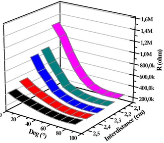
Figure 3. Inter-distance reduction between fixed ends. Figure 4 reports the results obtained in the resistance value variations investigating, as an example, the inter-distance reduction of the sensor of 5.1cms in length.
It can be noticed how the variation in resistance values is increased with reducing the inter-distance from 2.5cms to 2.1cms. This particular and uncommon aspect that we examined revealed an interesting sensor behavior since the reduction of the inter-distance correspond to a decrease of the curve radii of the carbon sensitive part of the sensors.
100 80 60 40 20 0 200,0k 400,0k 600,0k 800,0k 1,0M 1,2M 1,4M 1,6M 2,5 2,4 2,3 2,2 2,1 Interd istance ( cm) R ( oh m) Deg (°)
Figure 4. Resistance variation vs bending angle and vs inter-distance between sensor taped ends.
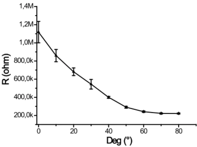
The most interesting consideration is that the more the investigated distance is reduced, the more the resistance variation is increased, leading to evident advantages. Anyway, it must be considered that there is a limit to the distance reduction, in the sense that it cannot become shorter than the joint being measured. Being the curve relative to the 2.1cms the most interesting one, error values relative to the measured resistance were analyzed. Figure 5 regards this error evaluation. This was obtained starting from 0° up to 90° of bending angle with a step of 10°. The standard deviation increases for higher bending angles, while it
0 20 40 60 80 200,0k 400,0k 600,0k 800,0k 1,0M 1,2M 1,4M R ( ohm ) Deg (°)
Figure 5. Error evaluation for measures of the 5.1 cms long sensor, taped ends at a inter-distance of 2.1 cms
For a comparison purpose, in figure 6 are reported the relative resistance variation versus bending angle for the 7.6cms, 5.1cms, 2.5cms length sensors with the inter-distances end taped respectively reduced to 3.5cms, 2.5cms and 1.2cms. Again the measured results are obtained when the bending angle is varied from 0° to 90° with a 10°step.
0 20 40 60 80 100 -100 -90 -80 -70 -60 -50 -40 -30 -20 -10 0 10 ∆R/ R (% ) Deg (°) 3.5 cm 2.5 cm 1.2 cm
Figure 6. Relative resistance changes vs bending angles for three different sensors
The sensor behavior shows a saturation aspect at higher bending angles. This behavior was not a problem for two main reasons: our system was able to discriminate bending values even when in the range of 80°-90°, thanks to the conditioning electronic circuitry, in addiction the thickness of the glove precludes the possibility of reaching physiological angles which fingers can arrive when out of the glove.
4. Virtual model
The basic model of the virtual hand was realized starting from Blender, which is an open source multiplatform software for 3D graphical applications. It has a robust feature set and has the interesting capabilities of texturing, skinning, animating, rendering. The 3D scene for the hand model was built by a mesh i.e. a point set that compose a spotted matrix. The pointed mesh represents the esoskeleton of the hand, so all the movements are performed through a careful mesh disposition.
The mesh can be visualized as an envelope covering the underlying structure made by several interconnected parts (bones), exactly as in a human skeleton. Every bone has got a pivot it can spatially rotate around. The skeleton repositioning corresponds to the rotation of every single junction, replacing all the mesh vertexes.
Every bone was described by two matrixes: a local one (local transform) and a combined one (combined transform). The local matrix describes translations and rotations with respect to its pivot. Obviously the bones are connected one another, so the translation and rotation of a bone influences all the others in a cascading way. This means that for every junction movement the combined matrix of all the junctions is recomputed in a recursive way:
Ci = Li * Ci-1
The combined matrix of the i-th junction is computed multiplying its local matrix by the combined matrix of the “father junction”.
Differing from the previously reported simplified kinematics model of human hand [8] and from some graphical results [9], we considered all fingers joints degree of freedom, including flex-extension and addu-abduction movements. We obtained graphical result strongly resembling to a real human hand. Just for the addu-abduction movements, we adopted the DirectX, i.e. a collection of application program interfaces for handling tasks related to multimedia. The DirectX software development kit (SDK) consists of runtime libraries in redistributable binary form and it works with a format called “x” just compatible with Blender output.
The virtual glove is controlled by C++ language routines. The calibration process is very simple because it is sufficient to define the minimum values (flat palm finger) and the maximum values (closed fist) of all the sensors, recurring to the previously recorded intermediate values during the characterization procedure.
Finally, the Graphic User Interface (GUI) was realized with Windows Application Program Interfaces (API) and it is programmed by C++ language.
Obviously not all movements are allowed. The antagonization between the insertion extensor and flexor tendons produces limited range of motions for each joint of each finger that, with a simplified schematization useful for our purposes, can be summarized as: 0°-120° for proximal inter-phalangeal (PIP) and 0°-90° for both metacarpo-phalangeal (MPC) and distal-interphalangeal (DIP) joints, being hyper-extension movements here neglected. In the same manner for abduction / adduction movements a motion range of 0°-25° was considered. This is schematized in Fig.7. Insertion Extensor Tendon Insertion Flexor Tendon (a) Extension Flexion (b) Adduction Abduction (c) Distal InterPhalangeal (DIP) Proximal InterPhalangeal (PIP) Metacarpo Phalangeal (MCP) (d)
Figure 7. Hand representation: (a) insertion extensor / flexor tendon
(b) extension / flexion movements (c) abduction / adduction movements (d) Distal / Proximal / Metacarpo Phalangeal
The program interface includes several controls, such as a recorder option so to recall the data stream upon request, zoom in/out, play/pause, save/open options. Then it is reported an error message if senseless measured input data are received and the single wrong acquisition value was changed according to an interpolation algorithm between the previous and the following measured data.
We experienced great advantages from the utilization of our 3D virtual model of the hand. During the pre-processing data phase, the model has been utilized as a helpful tool to verify the measurement repeatability. During the real-time visualization phase, the model allowed the hand visualization from different points of view, a continuous monitoring of the coherence in data stream and a rapid re-calibration if necessary. During the post-processing data phase, thanks to the model, it was possible to replay all the fingers movements in slow / rapid / frame-by-frame motion and to isolate just one finger at a time, removing the others from the view, in order to focus the operator’s attention only on some important details.
5. Results
The instrumented glove we developed demonstrated to be easy wearable thanks to the lycra based material. It was enough comfortable to be worn even for long time (in terms of hours). The arched solution proposed for the sensors demonstrated its validity.
For the virtual part reproducing all the movements of the sensors, the home-made 3D model is easily changeable, totally adaptable for different source data types. It demonstrated how finger movements can be
graphically viewed and how stored data can be analytically considered, re-played, viewed frame by frame, showing just one finger movement at a time, pausing the motion when necessary.
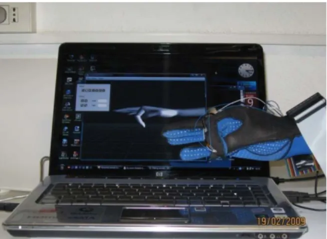
Figure 8. Virtual reality for a flex-extension movement
Figure 9. Virtual reality for a addu-abduction movement Future work can now be spent to enrich the facility here illustrated to implement the interaction with virtual objects expressly created in the environment.
6. Conclusion
Our instrumented glove technology has been ad hoc developed, so to presents the flexibility to take into account the specific needs of doctors, therapists and surgeons. Medicine and Health Care exigencies, especially motor rehabilitation, analysis of motor performance, ergonomics, medical education and training [3], may find the proposed virtual instrumentation a useful tool.
These interesting developments will provide an important advance in the understanding of the
functions of the real hand and furnish a simple way of assessing outcomes in a repeatable manner.
7. References
[1] G. Székely, R.M. Satava “Virtual reality in medicine” British Medical Journal, vol.319, n.13, 1999
[2] D.J. Sturman “Whole-Hand Input” Ph.D. dissertation, Massachusetts Institute of Technology, Cambridge, 1992. Available: http://xenia.media.mit.edu/~djs/thesis.ftp.html [3] L. Dipietro, A.M. Sabatini, P. Dario “A survey of
glove-based systems and their applications” IEEE
Transaction on Systems, Man, and Cybernetics – part C: Applications and Reviews, vol.38, n.4,
2008, pp. 461-482
[4] N.W. Williams, J.M.T. Penrose, C.M. Caddy, E. Barnes, D.R. Hose, P. Harley “A goniometric glove for clinical hand assessment” Journal of
Hand Surgery (British and European Volume, 2000) 25B: 2: 200-207
[5] L.K. Simone, E. Elovic, U. Kalambur, D. Kamper “A low cost method to measure finger flexion in individuals with reduced hand and finger range of motion” Proc. Of the 26th Annual International Conference of the IEEE EMBS, San Francisco,
CA, USA, sept. 1-5, 2004, pp. 4791-4794
[6] S. Wise, W. Gardner, E. Sabelman, E. Valainis, Y. Wong, K. Glassand, J. Drace, J. Rosen “Evaluation of a fiber optic glove for semiautomated goniometric measurements” J.
Rehabil. Res. Dev., vol. 27, no. 4, pp. 411-424,
1990
[7] T. Kuroda, Y. Tabata, A. Goto, H. Ikuta, M. Murakami “Consumer price data-glove for sign language recognition” Proc. 5th Intl Conf.
Disability, Virtual Reality & Assoc. Tech., Oxford, UK, 2004, pp. 253-258
[8] N.M. Noaman, A.R. Ajel, A.A. Issa “Design and implementation of a DHM glove using variable resistors sensors” Journal of Artificial Intelligence 1 (1): 44-52, 2008
[9] C.S. Fahn, H. Sun “Development of a Sensory Data Glove Using Neural-Network-Based Calibration” ICAT 2000