1
POLITECNICO DI MILANO
SCHOOL OF ENGINEERING
MASTER OF SCIENCE IN CIVIL ENGINEERING FOR RISK MITIGATION
M.Sc. THESIS
BEHAVIOR OF HIGH PERFORMANCE FIBER
REINFORCED CONCRETE BEAM EXPOSED
TO FIRE
Supervisor :
Authors
Prof. Matteo COLOMBO
Fatemeh POURSAFFARI (814216)
2
Acknowledgements
I would like to express my gratitude to my supervisor, Professor Matteo
Colombo for his useful comments, remarks and engagement through the
learning process of this mater thesis.
I would like to thank my parents, for their support and encourage. I could not
have completed this thesis without them.
I would like to gift this thesis to those who are seeking knowledge in this field.
3
Abstract
The topic of structural damage caused by fire has been discussed extensively by many researchers for over a decade. High performance concrete (HPC) can’t resist under fire exposure and the problem of spalling was seen in experimental tests. Using steel fibers in concrete not only develops concrete performance against fire and reduces spalling, but also increases structural resistance like resisting bending moment by taking into account tensile behavior of fibers. This study focuses on fire behavior of high performance fiber reinforced concrete (HPFRC) and presents the bending moment capacity of HPFRC beam exposed to fire using plane section approach (2D) and finite element method (3D). The time-temperature curve used in the thesis is based on standard fire named ISO834. The variation in material properties, caused by elevated temperature, has been studied, including strength and stiffness degradation. Compressive and tension constitutive laws change as temperature of the material increases according to EC3 Part 1.2. The behavior of the HPFRC beam when subjected to thermal loading followed by fire is presented and shows that there is degradation in bending moment capacity. Moreover, this degradation also has been studied under situation when there is cooling phases. Time of collapse in both approaches; 2D and 3D modeling are presented and compared with each other. The results from this study shows that the 3D model predicted a greater time to resist against fire while in 2D model the beam will fail sooner. We demonstrate neither models were able to simulate the spalling effect clearly in the experimental tests. At the end we suggest an effective way to solve this problem by adding polypropylene fibers which should get the concrete to resist better against spalling.
4
Astratto
Il tema dei danni strutturali causati dal fuoco è stato discusso in modo estensivo da molti ricercatori da oltre un decennio. Il calcestruzzo ad alte prestazioni (HPC) non può resistere ad alte temperature per via del problema di “spalling” riscontratosi nei test. L’utilizzo di fibre di acciaio all’interno del calcestruzzo, non solo riduce l’effetto di “spalling” ma ne aumenta anche la resistenza strutturale come per il momento flettente, tenuto in considerazione il comportamento a trazione delle fibre in acciaio. Questo studio si concentra sul comportamento della fibra nel cemento armato (HPFRC) e sull’analisi del momento flettente HPFRC durante l’esposizione alle alte temperature, utilizzando l’approccio “sezione piano” (2D) e il metodo degli elementi finiti (3D). La curva tempo-temperatura utilizzata nella tesi è stata ripresa da quella di “fuoco standard” ISO 834. Sono state studiate le variazioni delle proprietà del materiale sotto l’effetto delle elevate temperature, comprendendo anche la forza e il degrado di rigidezza. Le leggi costitutive di compressione e tensione cambiano in funzione della temperatura del materiale e si modificano in base alla EC3 parte 1.2. Si dimostrerà che esiste una degradazione nei parametri resistivi a momento flettente nelle travi UHPFRC sottoposte a carico termico a seguito di un incendio. Abbiamo voluto estendere l’analisi sul degrado del materiale anche nella fase di raffreddamento così da avere un’analisi più completa. I risultati di questo studio mostrano che il modello 3D ha predetto un tempo di resistenza al fuoco superiore rispetto a quello dell’analisi 2D. Dimostreremo che nessun modello è stato in grado di simulare l'effetto di “spalling” in modo chiaro. Alla fine suggeriremo che l’uso di fibre di polipropilene dovrebbe risultare un efficace metodo per ridurre il problema di spalling alle alte temperature.
5
Contents
Abstract ... 3 Astratto ... 4 Notation ... 8 1 : Introduction ... 15 2 : Literature Review ... 172.1 Literature review (Concrete in Ambient Temperature) ... 18
2.1.1 HPC ... 18
2.1.2 FRC ... 22
2.1.3 HPFRC ... 28
2.2 Literature review (Concrete at elevated temperature) ... 37
2.2.1 FRC degradation in elevated temperature ... 40
2.2.2 HPFRC degradation in elevated temperature ... 47
3 Heat Transfer ... 55
3.1 What is Heat and Temperature? ... 55
3.2 How is heat transferred? ... 55
3.2.1 CONDUCTION ... 55
3.2.2 CONVECTION ... 57
3.2.3 RADIATION ... 58
3.3 FOURIER EQUATION ... 61
3.3.1 Coordinate system ... 63
3.4 Steady versus transient heat transfer ... 65
3.5 Boundary and Initial conditions ... 65
4 : Engineering Problem ... 69
4.1 Geometry of the problem ... 70
4.2 Admixture of the beam ... 71
4.3 Exposing Fire ... 71
4.4 Material properties ... 72
4.4.1 Introduction ... 72
4.4.2 Thermal Properties of Materials ... 73
4.4.3 Mechanical Properties of Materials ... 84
4.4.4 Deformation properties of materials: ... 98
6 4.5 Acting Loads ... 103 4.5.1 Permanent loads (𝑮𝟏𝒌) ... 103 4.5.2 Imposed loads (𝑮𝟐𝒌) ... 104 4.5.3 Variable loads (𝑸𝟏𝒌) ... 106 4.5.4 Load combination ... 106
4.5.5 Acting Bending moment and shear force ... 106
5 : 2D model ... 108
5.1 Introduction ... 108
5.2 Creating numerical model ... 109
5.2.1 Part ... 109 5.2.2 Property ... 110 5.2.3 Assembly ... 113 5.2.4 Step ... 113 5.2.5 Interaction ... 114 5.2.6 Load ... 115 5.2.7 Mesh ... 115
5.2.8 Job and visualization ... 116
5.3 Fire analysis ... 117
5.3.1 Find temperature distribution ... 117
5.4 Plane section approach ... 120
5.4.1 Section Geometry and Discretization ... 122
5.4.2 Temperature distribution over section in a fixed time ... 124
5.4.3 Material Properties and their constitutive laws in ambient and degradation in high temperature ... 124
5.4.4 Discretize the curvature axis ... 128
5.4.5 Translational Equilibrium and find Neutral Axis (NA) ... 128
5.4.6 Bending moment capacity ... 130
5.4.7 Moment-curvature curves ... 130
5.5 Results ... 131
5.5.1 Time of failure ... 131
5.6 : 500 C isotherm method ... 133
1.6.5 Fire scenarios (Cooling phases) ... 139
6 : 3D Model ... 149
6.1 Numerical Models ... 149
7
6.1.2 Property of the material... 151
6.1.3 Assembly ... 157
6.1.4 Step ... 158
6.1.5 Interaction ... 158
6.1.6 Load , Boundary condition and predefined field ... 159
6.1.7 Mesh ... 160
6.1.8 Job and visualization ... 162
6.1.9 Conclusion ... 168
6.1.10 Different fire scenarios ... 168
6.5.55 Comparing results ... 171
7 Beam with slab (2D and 3D) ... 172
7.1.1 Geometry of beam with slab ... 172
7.1.2 Property of the Slab ... 173
7.1.3 Load ... 178 7.1.4 Mesh ... 178 7.1.5 2D model ... 180 7.1.6 3D model Results ... 188 8 Conclusion ... 191 9 Bibliography ... 194
8
Notation
l/d
Fibers Aspect ratio
℃
Degree of Celsius
𝐸
𝑑Design effect of actions in normal temperature design
Q
Heat flow
𝜆
Thermal conductivity
𝛼
𝑐Heat transfer coefficient or thermal convection coefficient
𝑃
Emissive power
𝜎
Stefan-Boltzmann constant.
𝑞
Global thermal flux of the black body towards vacuum
𝜀
𝑟𝑒𝑠Resultant emissivity
𝜙
Configuration factor
∇T
Temperature gradient
𝛼
Thermal diffusivity
𝑇
Temperature
T
Time
𝜌
Density
𝑐
Specific heat
𝛼
𝑐𝑖Coefficient of convective heat transfer
𝜖
Surface emissivity
𝑞̇
𝑏′′Heat flow at the boundary
𝑇
𝑔Gas temperature
𝑇
𝑏Boundary temperature
𝛼
𝑐Convection heat transfer coefficient
𝜖
𝑟𝑒𝑠Resulting emissivity
𝜃
Concrete temperature
𝐶
𝑐,𝑝𝑒𝑎𝑘Specific heat at the peak
∆𝑇
Temperature interval
𝑓
𝑐,𝜃Characteristic value of the compressive strength of concrete at elevated
temperature
𝜀
𝑐1,𝜃Strain corresponding to 𝑓
𝑐,𝜃𝜀
𝑐𝑢1,𝜃Ultimate strain
𝑓
𝑅1𝑘Serviceability characteristic flexural residual strength
𝑓
𝑅3𝑘Ultimate characteristic flexural residual strength
𝑙
Length at 20℃
∆𝑙
Temperature induced elongation
𝜃
𝑎Steel temperature
𝑄
1𝑘Live load
9
𝐺
2𝑘Imposed load
𝑀
𝐸𝑑Acting moment
𝑉
𝐸𝑑Acting shear
𝑆
𝑟𝑚Mean distance between cracks
𝑙
𝑐𝑠Characteristic length
Y
Distance between the neutral axis and the tensile side of the cross-section
𝑐
Concrete cover
𝜏
𝑏𝑚Mean bond strength between steel and concrete
𝑓
𝑐𝑡𝑚Mean concrete tensile strength
𝑘
Parameter to take into account the influence of concrete cover
∅
𝑠Rebar diameter
𝜌
𝑠,𝑒𝑓Effective reinforcement ratio
𝐴
𝑐,𝑒𝑓Effective area of concrete in tension
𝑅
𝑐𝑘Cubic compression resistance
𝜀
𝑐1Deformation at pick
𝜀
𝑐𝑢Ultimate deformation
𝛾
𝑐2Material coefficient
𝐸
𝑐1Second module of elastic
𝐸
𝑐0Tangent module of elastic
10 Table of Figures :
Figure 2-1 Microstructure of NSC ... 20
Figure 2-2Microstructure of HPC ... 21
Figure 2-3 Schematic of Stress-Strain curve in (a) HPC and (b) NSC under Uniaxial Compression ... 22
Figure 2-4: Stress-strain curves in compression for SFRC ... 25
Figure 2-5: influence of fiber content on tensile strength ... 25
Figure 2-6:overall behavior of NC, FRC with loa and high fiber volume ... 28
Figure 2-7: Type of cracks occur in concrete with fibers and without fibers ... 28
Figure 2-8 Trends of Cement-based materials... 30
Figure 2-9 Schematic comparison of the tensile response of three different strain-hardening FRC composites illustrating the tradeoff between strength and ductility (strain is to peak point only). ... 32
Figure 2-10: Fiber Quantity (vol,-%) ... 33
Figure 2-11: Typical force-deflection histories (Yoon,Marc,Woo 2002) ... 37
Figure 2-12:Thermal dilation, (Mitsuo and Hiroaki 2014) ... 39
Figure 2-13: Vapor pressure (Mitsuo and Hiroaki 2014) ... 39
Figure 2-14: Effect of PP fibres (Mitsuo and Hiroaki 2014) ... 40
Figure 2-15: Slab cast applying a unidirectional flow (Carvezan et all 2015) ... 41
Figure 2-16:Skein used to produce the fibers (a) (Carvezan et all 2015) ... 41
Figure 2-17: Stress versus COD curves. Tests carried out on an undamaged specimens 20C; b specimens exposed up to 200 C ... 43
Figure 2-18: Stress versus COD curves. Tests carried out on: a specimens exposed up to 400 C; b specimens exposed up to 600 C (Carvezan et all 2015) ... 44
Figure 2-19: Residual strengths versus temperature for SFRC and HPFRC feq1(T)/feq1(20) versus temperature (a); feq2(T)/feq2(20) versus temperature (b) ... 45
Figure 2-20: Fracture surfaces on specimen exposed to a thermal cycle up to 600 C; ... 46
Figure 2-21: Compressive strength after heating (Mpa) (Lau, 2004) ... 49
Figure 2-22: Flexural strength VS maximum heating temperature (Lau, 2004) ... 49
Figure 2-23: Compressive strength (poon et al 2004) ... 50
Figure 2-24: effect of temp. on compressive strength (Poon 2004) ... 51
Figure 2-25:Elastic modulus VS. temperatures (Lau, 2006) ... 52
Figure 2-26: Poisson's ratio vs temperature (Lau, 2006) ... 53
Figure 2-27: COD vs Stress in T=20, 200, 400 and 600 C (Felliceti et al 2000) ... 54
Figure 3-1 Conduction ... 56
Figure 3-2: Convection ... 58
Figure 3-3: Radiation ... 59
Figure 3-4 Fourier equation for heat flux ... 61
Figure 3-5: coordinates systems ... 63
Figure 3-6: Rectangular coordinate ... 64
Figure 3-7: Steady Vs. Transient state ... 65
Figure 4-1: Geometry of beam and slab (values in mm)... 69
Figure 4-2: Geometry of beam section in detail ... 70
Figure 4-3: Section Details of reinforcement bars ... 70
Figure 4-4: Standard fire IS0834 curve (Time-Tempreature) ... 72
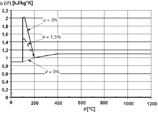
Figure 4-5: specific heat, as function of temperature at 3 different moisture (u=0, 1.5 and 3%) EN2-1-2 ... 74
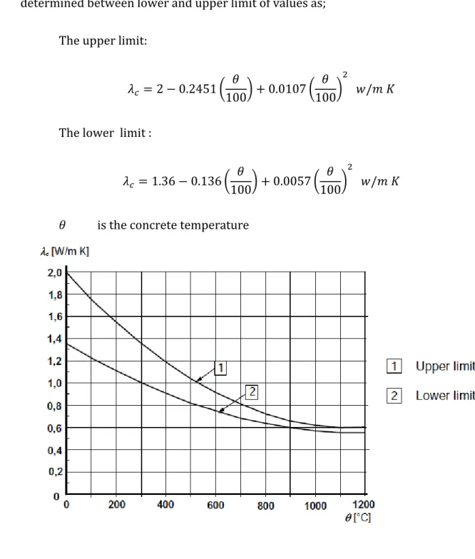
11 Figure 4-7: Upper and lower limit of the thermal conductivity of concrete as a function of the
concrete temperature. EN 1992-1-2 ... 78
Figure 4-8: Thermal conductivity of HPC and comparison with NC ... 79
Figure 4-9: Density of concrete as a function of temperature ... 81
Figure 4-10: Specific heat of steel as a function of temperature ... 83
Figure 4-11: Thermal Conductivity of carbon steel as a function of the temperature ... 83
Figure 4-12: Mathematical model for stress-strain relationships of concrete under compression at elevated temperatures. From EN 1992-1-2(2004) ... 87
Figure 4-13: compressive stress- strain relationship of concrete c110 for different values of the concrete temperature. The descending branch is chosen to be linear. Based on a figure from the fib Bulletin 46 (2008) ... 87
Figure 4-14: Simplified post-cracking constitutive laws: stress-crack Opening (continuous and dashed lines refer to softening and hardening post-cracking behavior, respectively) ... 89
Figure 4-15: Typical results from a bending test on a softening material (a); linear post-cracking constitutive law (b) For numerical analyses, more advanced constitutive laws are recommended, including first crack tensile strength. ... 90
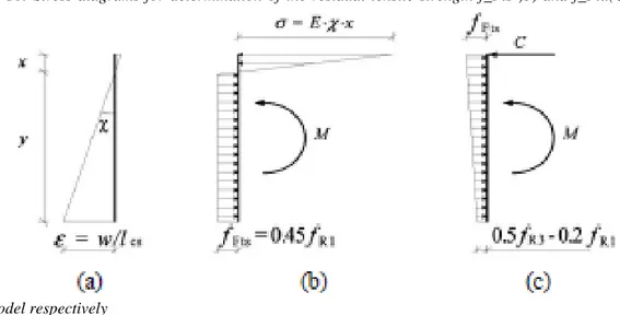
Figure 4-16: Stress diagrams for determination of the residual tensile strength f_Fts )b) and f_Ftu(C) for the linear model respectively ... 92
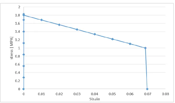
Figure 4-17: Constitutive law for HPFRC beam in tension ... 93
Figure 4-18: Constitutive law for FRC Slab in tension ... 94
Figure 4-19: Constitutive law for HPFR in tension for different temperatures ... 94
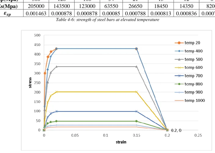
Figure 4-20: Stress-strain relationship for carbon steel at elevated temperatures. EN1993.1.2 ... 96
Figure 4-21: Reduction factors for the stress-strain relationship of steel at elevated temperatures (EN1993.1.2) ... 97
Figure 4-22: Reduction factors for stress-strain relationship of carbon steel at elevated temperatures (EN1993.1.2) ... 97
Figure 4-23: Constitutive law for steel bars at elevated temperature, Compression and tension ... 98
Figure 4-24: Thermal expansion of Concrete(Kodur 2014) ... 99
Figure 4-25: Relative thermal elongation of carbon steel as a function of the temperature ... 101
Figure 4-26; Category of imposed loads ... 105
Figure 5-1: main procedure of the plane section approach ... 108
Figure 5-2: create part (Geometry of the beam) ... 110
Figure 5-3: Density over temperature of HPC ... 111
Figure 5-4: Thermal conductivity of HPC ... 112
Figure 5-5: Specific heat over temperature ... 113
Figure 5-6: interaction assigned to the bottom side of the beam ... 114
Figure 5-7: Mesh elements of the beam section ... 115
Figure 5-8: Nodal temperature after 200 min ... 116
Figure 5-9: Heat Flux after 200 min ... 116
Figure 5-10: Field output (temperature over depth of cross section after 200 min) ... 117
Figure 5-11: Defining points over cross section ... 118
Figure 5-12: Temperature over time in different nodes ... 119
Figure 5-13: Temperature distribution of section in different times ... 119
Figure 5-14: Defining geometry in Matlab code ... 122
Figure 5-15: Discretization of cross section ... 122
12 Figure 5-17: compressive stress- strain relationship of concrete c110 for different values of the concrete temperature. The descending branch is chosen to be linear. Based on a figure from the fib
Bulletin 46 (2008) ... 126
Figure 5-18: Constitutive law for HPFR in tension for different temperatures ... 128
Figure 5-19: Establish translational equilibrium to find N.A ... 129
Figure 5-20: General equation for translational forces acting on the section ... 129
Figure 5-21: Calculating bending moment capacity of the beam by knowing strains and its corresponding stresses over cross section. ... 130
Figure 5-22: Moment curvature at different times ... 131
Figure 5-23: Bending moment capacity over time ... 132
Figure 5-24: 500 Degree isotherm and simplified assumptions for concrete strength ... 133
Figure 5-25: Position of 500 C isothrem in different steps ... 134
Figure 5-26: Conventional calculation methods: ultimate bearing capacity ... 136
Figure 5-27: Bending Moment Vs Time (500'C method) ... 137
Figure 5-28: Time of failure (acting Bending moment and bending moment capacity of section according to 500'C and FEM) ... 138
Figure 5-29: Different fire scenarios and cooling phases ... 139
Figure 5-30: Temperature distribution over depth for different fire scenarios at different times .... 140
Figure 5-31: Temperature distribution over depth for different fire scenarios at different times .... 141
Figure 5-32: Moment-Curvature for fire Scenario 1 at different times ... 142
Figure 5-33:Bending moment capacity over time (Cooling 30 min) ... 143
Figure 5-34:Moment-Curvature for fire Scenario 2 at different times ... 144
Figure 5-35::Bending moment capacity over time (Cooling 60 min) ... 144
Figure 5-36:Moment-Curvature for fire Scenario 3 at different times ... 145
Figure 5-37: Bending moment capacity over time (Cooling 90 min) ... 145
Figure 5-38:Moment-Curvature for fire Scenario 4 at different times ... 146
Figure 5-39: Bending moment capacity over time (Cooling 120 min) ... 146
Figure 5-40: Capacity bending moment-time for all scenarios ... 147
Figure 5-41: Resisting bending moment-time for beam exposed to ISO834 and beam exposed to different cooling phases... 148
Figure 6-1: Geometry of concrete beam (3D model) ... 150
Figure 6-2: Geometry of steel bars ; a)steel bars in plane section b)steel bars after extrusion... 150
Figure 6-3: compressive stress- strain relationship of concrete c110 for different values of the concrete temperature.(refer to 4.4.3.1.1) ... 152
Figure 6-4: Constitutive law for HPFR in tension for different temperatures (refer to 4.4.3.1.2) ... 154
Figure 6-5: constitutive law of steel ... 156
Figure 6-6: procedure to assemble steel bars and HPFRC beam ... 157
Figure 6-7: Interactions' input to FEM model ... 158
Figure 6-8: Exposed surface ... 158
Figure 6-9: Loads in FEM model ... 159
Figure 6-10: Convergence check -Quilt option ... 161
Figure 6-11: evolution of nodal temperature for different steps ... 162
Figure 6-12: Stress over time for point B ... 163
Figure 6-13: Von Mises Stresses evolution for 3 steps ... 163
Figure 6-14: Plastic strain evolution over time ( for three different steps) ... 164
Figure 6-15: Total strain evolution over time (for three different steps) ... 164
13
Figure 6-17: total and plastic Strain over time of a central point ... 166
Figure 6-18: Total strain and plastic strain over time of a central point in compression zone ... 167
Figure 6-19: total strain and plastic strain of a central point in steel bars ... 167
Figure 6-20: Fire exposure scenarios considered in 3D model ... 168
Figure 6-21: Strain-time of scenario 3 for a central point ... 169
Figure 6-22: Thermal distribution of beam exposed to fire with cooling at 80 min ... 170
Figure 6-23: Maximum principal stresses on beam section at time of failure ... 170
Figure 7-1:Model of beam with slab ... 172
Figure 7-2: Constitutive law for slab in compression ... 175
Figure 7-3: Constitutive law in tension for slab ... 177
Figure 7-4: Loads acting on the beam with slab model ... 178
Figure 7-5: Mesh of beam with slab in 3D model ... 179
Figure 7-6: Meshing of beam with slab in 2D model ... 179
Figure 7-7:Results of FEM: both slab and beam are exposed to fire with cooling started at 60 min. Results at time 0, 5,12,24,43,63 minutes) ... 181
Figure 7-8: Results of FEM: both slab and beam are exposed to fire with cooling started at 60 min, Results at time 83,103,123,143,163,182 and 200 minutes) ... 181
Figure 7-9: Temperature distribution over depth at time 60 min ... 182
Figure 7-10: Temperature distribution over depth at time 100 min ... 182
Figure 7-11: Temperature distribution over depth at time 130 min ... 183
Figure 7-12: Temperature distribution over depth at time 150 min ... 183
Figure 7-13:Moment-curvature of beam with slab for cooling started at 30 min ... 184
Figure 7-14:Moment-curvature of beam with slab for cooling started at 60 min ... 184
Figure 7-15:Moment-curvature of beam with slab for cooling started at 90 min ... 185
Figure 7-16:Moment-curvature of beam with slab for cooling started at 120 min ... 185
Figure 7-17: Moment-time diagram of beam with slab... 186
Figure 7-18:Moment-curvature of beam with slab for cooling started at 60 min (all sides are exposed to fire) ... 187
Figure 7-19: Slab exposed to fire scenario 60 ... 187
Figure 7-20: Nodal temperature for different steps (only bottom of the beam exposed to fire) ... 188
Figure 7-21: Temperature evolution over time for a specific point located at center and bottom of the beam ... 189
Figure 7-22: Displacement over time for a central point in the middle of the span ... 189
Figure 7-23: Strain evolution over time for a point in center and in bottom of the beam ... 189
Figure 7-24: Strain evolution over time for beam in 3D view ... 190
14 Tables:
Table 2-1: Different mineral admixtures used in HPC ... 19
Table 2-2: Different chemical admixtures used in HPC ... 19
Table 2-3: Characteristics of High Strength Concretes ... 21
Table 2-4: Mix design (Caverzan et all 2015) ... 40
Table 3-1: Typical values of 𝛼𝑐 ... 58
Table 3-2: Typical values for 𝜀𝑚𝑒𝑚𝑏𝑒𝑟 ... 61
Table 3-3: Emissivity/Convection values for Un/Exposed surfaces ... 68
Table 4-1:Geometry specifications ... 71
Table 4-2: HPFRCC- mix composition ... 71
Table 4-3: values of the main parameters of the stress-strain relationships of normal weight concrete with siliceous or calcareous aggregates concrete at elevated temperatures. Linear interpolation may be used. Copied from EN 1992-1-2 (2004). ... 85
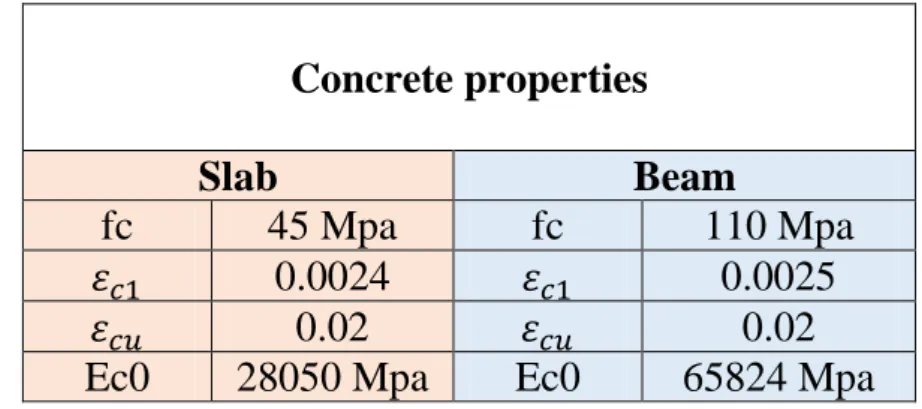
Table 4-4:Mechanical properties of Concrete for Slab and Beam ... 86
Table 4-1:Values for τ_bm for deformed reinforcing bars (fib MC2050, Table 7.6-2) ... 91
Table 4-6: strength of steel bars at elevated temperature ... 98
Table 4-7: nominal density of construction materials ... 104
Table 4-8: Imposed loads on floors, balconies and stairs in buildings according to Eurocode ... 106
Table 5-1: Coordinates of he point in 2D model ... 109
Table 5-2: Density over temp input of numerical model ... 110
Table 5-3: Conductivity over temperature input of numerical model... 111
Table 5-4: temperature-specific heat value for concrete input of Abaqus ... 112
Table 5-5Penetration of 500 degree isotherm ... 134
Table 5-6: New width and height after penetration of 500 C isotherm ... 135
Table 5-7: Temperature of bars over time of exposure ... 135
Table 5-8: Results of degradation of steel bars due to increasing of temperature ... 136
Table 5-9: Results of Bending Moment Capacity (method : 500'C isotherm) ... 137
Table 6-1: Coordinates of the steel bars points ... 151
Table 6-2: Table of Young's Modulus variation by increasing temperature ... 152
Table 6-3: plasticity properties of concrete input of 3D model ... 152
Table 6-4: Table of yield stress-Temperature value of concrete input of 3D model ... 153
Table 6-5: Young's Modulus over temperature increasing input of steel in 3D model ... 155
Table 6-6: plastic strain of steel bars in different temperature ... 156
Table 7-1: Density over temp input of numerical model ... 173
Table 7-2: Conductivity over temperature input of numerical model... 173
Table 7-3: Temperature-specific heat of concrete of slab input of Abaqus ... 174
Table 7-4: Plasticity properties of slab input of Abaqus ... 174
Table 7-5: Table of value of stress-strain over temperature for slab ... 176
15
1 : Introduction
Normal concrete is typically resistant against fire and elevated temperatures, but the HPC may result in failure. The high packing density of HPC results in low permeability and superior durability over normal concretes. The failure that typically occurs for HPC is explosive spalling at high temperatures. Thermal spalling is mainly due to combination of two phenomena;
1- Increasing of vapor pressure caused by the evaporation of free and bound water trapped in the cementitious matrix.
2- Unequal thermal expansion between the concrete core and surface
Spalling is more crucial for steel reinforced concrete, because by reducing the cross section the convention steel reinforcement may expose to high temperatures. The use of steel and polypropylene or steel fibers has shown to mitigate the problem of spalling at high temperatures. By adding these fibers to HPC mix the resistance of matrix to elevated temperature increases. Also, the addition of fibers allows for higher ductility and energy dissipation capacity. Moreover, it allows to optimize the elements sections, while reducing the total masses and the execution costs. Addition of fibers increase the tensile strength of concrete and constitutive law can be also established for tensile zone. The focus of this research is to investigate the residual mechanical properties of high performance fiber reinforced concretes at elevated temperatures. Heating of the beam is studied in two different heating regimes, with cooling phase and without cooling phase. The body of thesis consists of seven chapters as follows;
Chapter 1 represents an overview to the thesis
Chapter 2 represents an introduction to HPFRC both in ambient temperature and in elevated temperature according to articles and experimental works already done by researchers.
16
Chapter 3 is mainly about the heat transfer and an introduction of engineering problem regarding thermal transmission trough the matters.
Chapter 4 presents engineering problem of this work including geometry of the problem, material properties, fire exposure, acting loads and any other parameters required to model the problem numerically.
In Chapter 5 the plane section approach used for finding the bending moment capacity. Applying this approach, the problem was modeled in two dimension and the plane section approached has been introduced and discussed.
Chapter 6 works with 3D model of the whole problem using software of Abaqus CAE (FEM) and its aim is to find the overall behavior of the HPFRC beam exposed to fire in 3D.
Chapter 7 is going further by considering the beam with its slab and finding the results in both 2D and 3D approaches to understand the contribution of slab in bearing capacity of the problem.
Chapter 8 is conclusion on the results of the last three chapters and gives more perspective for future studies.
17
2 : Literature Review
In the last two decades, concrete technology has enabled the manufacturing of concrete that has a uniaxial compression strength of about (or more than) 100 MPa, implementing conventional mixing technologies. This concrete has been commonly referred to as high strength concrete (HSC). Subsequently, study of the structural behavior of HSC has increased during this period together with the research and development on the material properties. Research on HSC material properties has shown that, besides its increased strength, HSC is also characterized by relatively increased brittleness. Adding steel fibers is one way of enhancing the structural performance of HSC through an increase in the concrete toughness, yielding high performance concrete (HPC). The use of steel fibers has been developed in recent years (Dancygier & Savir, 2006).
Therefore, in order to have a better understanding about High performance fiber reinforced concrete (HPFRC) the behavior of HPC and FRC according to different articles and reports have been discussed separately. After that, the behavior of HPFRC was presented according to articles and studies that were performed on HPFRC directly and the result of tests and studies will be presented. After that the performance of HPFRC when exposed to fire in different researches presented.
18
2.1 Literature review (Concrete in Ambient Temperature)
2.1.1 HPC
Based on the compressive strength; concrete is normally classified as normal strength concrete, high strength concrete and ultra-strength concrete. To achieve high strength, it is necessary to use high cement content with the lowest possible w/c ratio which invariable affect the workability of the matrix (Krstulovic, Haghayeghi, & Uang, 1995). Therefore, the main difference between conventional concrete and High-Performance Concrete is essentially the use of chemical and mineral admixtures (Kanmalai, Partheeban, & Felix, 2008). The admixtures can be added to cement concrete as a partial replacement of cement along with superplasticiser as a water reducer to get the high performance. Generally speaking, the definition ‘high performance’ is meant to distinguish structural materials from the conventional ones, as well as to optimize a combination of properties in terms of final applications related to the civil engineering. The most interesting properties are, for example, strength, ductility, toughness, durability, stiffness, thermal resistance, even though it is necessary to take into account the final cost of the material and, above all, of the produced structural members (GUERRINI, 2000).
2.1.1.1 Mixture of HPC
Mineral and chemical admixtures play an important role in the production of High Performance Concrete. Mineral Admixtures form an essential part of the High Performance Concrete mix. They are used for various purposes depending upon their properties. Table 2-1 shows different types of mineral admixtures with their particle characteristics.Different Chemical admixtures (Super plasticizers) are extensively used in development of High Performance Concrete with very low water cement ratio are represented in Table 2-2 with their functions (Vatsal & Niraj, 2013).
19
Mineral Admixtures Classification Particle characteristics
Ground granulated blast furnace slag
Cementitious and pozzolanic Unprocessed material are grain like sand, ground to size< 45 𝜇𝑚 particles and
have atough texture Fly ash Cementitious and pozzolanic Powder consists of particles
size 45 𝜇𝑚, 10% to 15% are more than 45 𝜇𝑚, solid spheres and general smooth Silica fume Highly active pozzolanic Fine powder consisting of
solid spheres of 0.1 𝜇𝑚 average diameter Rice husk ash Highly active pozzolanic Particles are <45 𝜇𝑚 in size
and have cellular and porous structure
Table 2-1: Different mineral admixtures used in HPC
Chemical Admixtures Function
Superplasticizer To reduce the water requirement by 15 % to 20% without affecting the workability leading to a high strength and dense concrete
Accelerator To reduce the setting time of concrete thus helping early removal of forms and therefore used in cold weather concreting
Retarder To increase the setting time by slowing down the
hydration of cement and therefore are preferred in places of high temperature concerting
Water reducing admixture To achieve certain workability (slump)at low water cement ratio for a specified strength thus saving on the cement
Air entraining admixture To entrain small air bubbles in concrete which act as rollers thus improving the workability and therefore very effective in freeze-thaw cycles as they provide a
cushioning effect on the expanding water in the concreting in cold climate
Table 2-2: Different chemical admixtures used in HPC
The composition of HPC usually consists of cement, water, fine sand, superplasticizer, fly ash and silica fume. Sometimes, quartz flour and fiber are the components as well. The key elements of high performance concrete can be summarized as follows:
20
- Large quantity of silica fume (and/or other fine mineral powders), - Small aggregates and fine sand,
- High dosage of superplasticizers,
- Heat treatment and application of pressure which are necessary for ultra high strength concrete after mixing (at curing stage).
The microstructure of concrete can be described in three aspects, namely composition of hydrated cement paste, pore structure and interfacial transition zone. The hydrated cement paste is in fact the hydration products when cement is reacted with water. The pore structure refers to the gel pores, capillary pores and voids, as well as their connections within the hardened concrete. The interfacial transition zone refers to the boundaries between the cement paste, and aggregates or particles of admixtures. The composition of NSC is relatively simple, which consists of cement, aggregate and water. Figure 2-1 shows the microstructure of NSC.
Figure 2-1 Microstructure of NSC
In HPC, very fine admixture, such as silica fume or fly ash, is added into the design mix so that the empty space inside concrete can be reduced significantly. Meanwhile, the pore connectivity is lowered because the very fine particles effectively block the capillary network. Thirdly, the interfacial transition zone can be toughened by lowering the locally high water-to-cement ratio and by improving the particle packing in this zone. Superplasticizer is added into the concrete mix so that a very low water-to-cement ratio (less than 0.2) become feasible to be adopted. Fine admixtures, like silica fume or fly ash, is added as well to improve the particle packing in the interfacial transition zone. It is noticed that in order to improve the concrete performance, admixture is a necessary
21
component which must be added into the design mix in order to generate HPC. Hence, its microstructure is quite different from that of NSC. Figure 2-2 (Oral & Denvid).
Figure 2-2Microstructure of HPC
2.1.1.2 Strength of HPC
In practice, concrete with a compressive strength less than 50MPa is regarded as NSC, while high strength concrete (HSC) may be defined as that having a compressive strength of about 50MPa. Recently, concrete with the compressive strength of more than 200MPa has been achieved. Table 2-3 shows the characteristics of different type of HSC with various compositions (Oral & Denvid).
It is also studied by Kanmalali and he stated that it is recognized that the use of silica fume as a partial replacement for cement provides a significant increase in strength of concrete (Kanmalai, Partheeban, & Felix, 2008).
Regular High strength Very high strength
Compressive strength (MPa)
<50 50-100 100-150
Water-to-cement ratio >0.45 0.45-0.30 0.30-0.25
Chemical admixtures Not required
Water-reducing admixture or superplasiticizer
Superplasticizer
Mineral admixtures Not required
Fly ash Silica fume
Permeability (m/s) >10−12 10−13 <10−14
22
2.1.1.3 Ductility of HPC
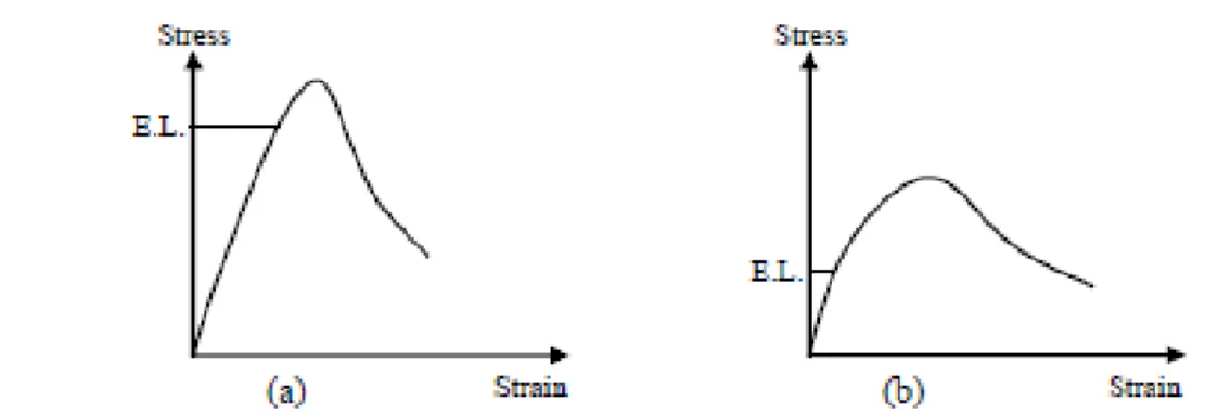
Research on HPC material properties has shown that, besides its increased strength, HPC is also characterized by relatively increased brittleness (Dancygier & Savir, 2006). Meanwhile, HPC has a larger Young’s modulus than NSC and the post-peak softening branch is steeper. HPC behaves linearly up to a stress level which is about 90% of the peak stress, whereas lower strength concrete shows nearly no linear part at all. When the peak stress has been reached, the stress decays rapidly in high strength concrete. A qualitative comparison of uniaxial compressive stress-strain curve of HSC with that of NSC is given in Figure 2-3.
Figure 2-3 Schematic of Stress-Strain curve in (a) HPC and (b) NSC under Uniaxial Compression
2.1.2 FRC
Fibers have been used to reinforce brittle materials since ancient times. The use of straw in sun baked clay bricks; mixing of horse hair in plasters were widespread in early civilizations. Apart from the role of fibers is essentially to arrest any advancing cracks by applying pinching forces at the cracks tips, thus delaying their propagation across the matrix and both these methods provide tensile strength to the concrete members, and they however do not increase the inherent tensile strength of concrete itself creating a distinct slow crack propagation stage (Meikandaan, Arunkumar, & PonPaul, Dec 2012).
23
Fiber reinforced concrete (FRC) may be defined as a composite materials made with Portland cement, aggregate, and incorporating discrete discontinuous fibers (Chanh).
Fibers are produced from different materials in various shapes and sizes. Typical fiber materials are;
- Steel Fibers: Straight, crimped, twisted, hooked, ringed, and paddled ends. Diameter range from 0.25 to 0.76mm.
- Glass Fibers: Straight. Diameter ranges from 0.005 to 0.015mm (may be bonded together to form elements with diameters of 0.13 to 1.3mm).
- Natural Organic and Mineral Fibers Wood, asbestos, cotton, bamboo, and rock-wood. They come in wide range of sizes.
- Polypropylene Fibers: Plain, twisted, fibrillated, and with buttoned ends.
- Other Synthetic Fibers Kevlar, nylon, and polyester. Diameter ranges from 0.02 to 0.38mm.
A convenient parameter describing a fiber is its aspect ratio (LID), defined as the fiber length divided by an equivalent fiber diameter. Typical aspect ratio ranges from about 30 to 150 for length of 6 to 75mm (WAFA, 1990).
Addition of fibers to concrete influences its mechanical properties which significantly depend on the type and percentage of fiber. Fibers with end anchorage and high aspect ratio were found to have improved effectiveness. It was shown that for the same length and diameter, crimped-end fibers can achieve the same properties as straight fibers using 40 percent less fibers. In determining the mechanical properties of FRC, the same equipment and procedure as used for conventional concrete can also be used.
24
2.1.2.1 Mixture of FRC
As with any other type of concrete, the mix proportions for SFRC depend upon the requirements for a particular job, in terms of strength, workability, and so on. Several procedures for proportioning SFRC mixes are available, which emphasize the workability of the resulting mix. However, there are some considerations that are particular to SFRC.
In general, SFRC mixes contain higher cement contents and higher ratios of fine to coarse aggregate than do ordinary concretes, and so the mix design procedures the apply to conventional concrete may not be entirely applicable to SFRC. Commonly, to reduce the quantity of cement, up to 35% of the cement may be replaced with fly ash. In addition, to improve the workability of higher fibre volume mixes, water reducing admixtures and, in particular, superlasticizers are often used, in conjunction with air entrainment.
The second factor which has a major effect on workability is the aspect ratio (l/d) of the fibres. The workability decreases with increasing aspect ratio, in practice it is very difficult to achieve a uniform mix if the aspect ratio is greater than about 100 (Chanh).
2.1.2.2 Compressive and tensile strength of FRC
The presence of fibers may alter the failure mode of cylinders, but the fiber effect will be minor on the improvement of compressive strength values (0 to 15 percent). Many experimental researches have been written in order to describe the effect of fibers on Compressive and tensile strength of concrete. For example Meikndaan performed number of tests on a FRC beam and the results indicated that there is 13.29% increase in compressive strength as compared with normal plain concrete (without fibers). Meanwhile adding fibers increases 11.96% of splitting tensile strength as compared with normal plain concrete. Moreover, there is 26.56% increase in Modulus of elasticity as compared with normal plain concrete (Meikandaan, Arunkumar, & PonPaul, Dec 2012).
According to Johnston, (Figure 2-4) fibres do little to enhance the static compressive strength of concrete, with increases in strength ranging from essentially nil to perhaps 25%. Even in members which contain conventional reinforcement in addition
25
to the steel fibres, the fibres have little effect on compressive strength. However, the fibres do substantially increase the post-cracking ductility, or energy absorption of the material (Johnston, 1974).
Figure 2-4: Stress-strain curves in compression for SFRC
Figure 2-5: influence of fiber content on tensile strength
According to Johnston, for more or less randomly distributed fibers, the increase in tensile strength is much smaller, ranging from as little as no increase in some instances to perhaps 60%, with many investigations indicating intermediate values, as shown in
26
Figure 2-5. Splitting-tension test of SFRC show similar result. Thus, adding fibers merely to increase the direct tensile strength. However, as in compression, steel fibers do lead to major increases in the post-cracking behavior or toughness of the composites (Chanh; Johnston, 1974).
The addition of steel fibers to a reinforced concrete beam is known to increase its shear strength and if sufficient fibers are added, a brittle shear failure can be suppressed in favor of more ductile behavior (Adebar, Mindess, Pierre, & Olund, 1997).
According to Kwak et al , the fibers appeared to be effective in delaying the formation of cracks, or at least in arresting their initial growth. As the steel fiber volume increase the failure mode changed to a combination of shear and flexure. The experimental results form 12 fiber-reinforced concrete beams demonstrate the steel fiber volume fraction, a/d (shear span-depth ratio), and concrete compressive strength on the onset of shear cracking, shear strength, ultimate deflection and failure mode. The increase in strength was particularly large (69 to 80%) for beams with the smallest a/d (Kwak, Eberhard, Kim, & Kim, 2002).
The presence of 3 percent fiber by volume was reported to increase the splitting tensile strength of mortar about 2.5 times that of the unreinforced one.
2.1.2.3 Ductility of FRC
Concrete is a brittle material, and usage of steel fibers considerably increases its toughness, the energy absorption capacity, among other contributions, like more ductile behavior prior to the ultimate failure, reduced cracking, and improved durability (Fatih , Tefaruk, & Kamura, 2007).
In a research study, the effect of SFs on cracks in RC beams was investigated, and it was concluded that a SF dosage of 30–40 kg/m3 was appropriate to have an appreciable
27
2.1.2.4 Durability of steel fibers
A ten-year exposure of steel fibrous mortar to outdoor weathering in an industrial atmosphere showed no adverse effect on the strength properties. Corrosion was found to be confined only to fibers actually exposed on the surface. Steel fibrous mortar continuously immerse in seawater for 10 years exhibited a 15 percent loss compared to 40 percent strength decrease of plain mortar.
2.1.2.5 Modulus of elasticity of FRC
Modulus of elasticity of FRC increases slightly with an increase in the fibers content. It was found that for each 1 percent increase in fiber content by volume there is an increase of 3 percent in the modulus of elasticity.
2.1.2.6 Shear capacity of FRC
Addition of fibers increases shear capacity of reinforced concrete beams up to 100 percent. Addition of randomly distributed fibers increases shear-friction strength, the first crack strength, and ultimate strength.
High Strength Concrete Fibers increases the ductility of high strength concrete. The use of high strength concrete and steel produces slender members. Fiber addition will help in controlling cracks and deflections.
2.1.2.7 Cracking and Deflection
Tests have shown that fiber reinforcement effectively controls cracking and deflection, in addition to strength improvement. In conventionally reinforced concrete beams, fiber addition increases stiffness, and reduces deflection
28
Figure 2-6:overall behavior of NC, FRC with loa and high fiber volume
Figure 2-7: Type of cracks occur in concrete with fibers and without fibers
2.1.3 HPFRC
The development from normal strength (plain) concrete to high strength (plain) concrete with a cylinder strength of about 100 N/mm2 took approximately a decade. A
29
maximum, since the strength of the aggregate particles does not allow a further increase of the bearing capacity of the concrete.
Fiber reinforced concrete is as well a material which has encountered limits in its development due to reasons related to its composition. In this case it was the reduced workability of concretes with increasing volumes of fibers which impeded the step to becoming a real high performance material. As a reaction on this limitation due to workability, interesting concepts were developed to increase the maximum volume of fibers and their efficiency (Joost, 2009) .
2.1.3.1 Examples of HPFRC
High-performance fiber-reinforced cement-based composites were derived starting from high-performance materials currently defined using acronyms such as:
- SIFCON (Slurry Infiltrated Fiber Concrete) - SIMCON
- DSP (Densified with Small Particle systems)
- RPC (Reactive Powder Concrete) or BPR (Bétons de Poudres Réactives) - BSI (Béton Spécial Industriel – Special Industrial Concrete)
- MDF (Macro-Defect-Free) cements
The main result obtained from the development of these materials is the optimum combination of strength and ductility/toughness, approaching the structural properties of steel and other common building materials (plastics, composites) Figure 2-8 (Shah, 1995).
30
Figure 2-8 Trends of Cement-based materials
SIFCON and SIMCON are the most popular type of HPFRC, therefore it is better to have a brief introduction on them.
In the nineties the material SIFCON (Slurry Infiltrated Fibre CONcrete) was developed, the fibers of which are placed and compacted first, after which the space between them was filled with a cement-based slurry. On the other words, SIFCON is a type of fibre reinforced concrete but it is produced using a method very different from that for ordinary fibre concrete. Fibre concrete is usually produced by adding fibres into fresh concrete. All components are then mixed together and cast into a mould (Svermova & Bartos, 2002). In this way a fiber content of 12–13% volume can be reached, which is about 10 times the maximum volume obtained in conventional fiber concrete. Very large strain capacities (10–15%) and high strengths (120–140 MPa) can be achieved in this way (Naaman A. , 23 Jun 1991) (Joost, 2009) .
Another concept was SIMCON (Slurry Infiltrated Mat Concrete). To produce this concrete, a manufactured continuous mat of interlocking discontinuous steel fibers is placed in a form, subsequently infiltrated with a flowable cement-based slurry (Kristulovic, Dogan, Uang, & Haghayeghi, 1997). However, on the basis of advanced ideas with regard to the composition of fiber reinforced concrete mixtures, new types of fiber reinforced concretes with compressive strengths up to 200 N/mm2 and fiber contents up
to 2.5 vol.%(175 kg/m3) became available (Joost, 2009).
SIFCON and SIMCON are made by pre-placing short, discontinuous steel fibers or continuous stainless steel fiber-mats (from 5 to 20% by volume), respectively, followed
31
by infiltrating the fibers with a cement-based slurry. SIMCON can successfully interact with existing structural elements, substantially increasing load capacity, compressive and flexural strength, energy-absorption capacity, ductility and toughness. However, to achieve the maximum benefit of SIMCON retrofit it is important to prevent delamination of the SIMCON layer. Based on the observed cracking mechanism, it can also be anticipated that the use of SIMCON would markedly improve durability of retrofitted elements (Krstulovic, Haghayeghi, & Uang, 1995).
Fiber contents in HPFRC plays significant role but it doesn’t mean that by increasing to a high value, the strength improved with the same order. On the other hand, extremely high fiber contents do not increase the compressive strength by as much as might be expected. For instance, San et al (Sun, Pan, Yan, Qi, & Chen, 1999) found that SIFCON with fiber contents of up to 10% by volume had compressive strengths only in the range of about 25–50% higher than the plain concrete matrix; different fiber geometries led to quite different increases in strength. Similarly, using SIMCON, Krstulovic (Krstulovic, Haghayeghi, & Uang, 1995) found an increase of about 30% in going from a fiber volume of 2.16% to 5.39%. It may be that for these very high fiber volume materials, difficulties in achieving full compaction may lead to increased matrix porosities (Bentur & Mindess, 1990).
However, Very high fiber volumes, appear to be more effective in tension than in compression. (Krstulovic, Haghayeghi, & Uang, 1995) found about a 150% increase in the tensile strength of SIMCON on increasing the steel fiber content from 2.16% to 5.25% (Naaman & Reinhardt, 2006).
32
Figure 2-9 Schematic comparison of the tensile response of three different strain-hardening FRC composites illustrating the tradeoff between strength and ductility (strain is to peak point only).
Moreover, it is worth noticing that, in conventional reinforced fiber concrete the fibers are relatively large in comparison with the aggregate particles. The fibers are activated as soon as a major crack in the concrete occurs: In HPFRC the fibers are much finer: they are already activated when micro-cracks occur in the concrete (Markovic, 2006) (Joost, 2009). There are considerable differences between concretes with only one type of fiber and concretes with combinations of fibers. Figure 2-10 shows for instance that a mixture with 2 vol.% of fibers (155 kg/m3) with l = 13 mm reached a flexural tensile
strength of 25 N/mm2 whereas a mixture with 1 vol.% short fibers (13 mm) plus 1 vol.%
long fibers (40 mm) reaches a flexural tensile strength of 40 N/mm2. t can as well be seen
in the diagram that 1 vol.% of short fibers combined with 0.5 vol.% of long fibers (40 mm) offers the same flexural tensile strength as 2 vol.% of short fibers. This shows that by combining different types of fibers optimization of mechanical properties can be achieved (Joost, 2009). As the fiber content increased, both the maximum applied load and ultimate deflection increased also (Kwak, Elberhard, Kim, & Kim, August 2002).
33
Figure 2-10: Fiber Quantity (vol,-%)
2.1.3.2 Strength of HPFRC
The addition of fibers to NSC and HPC columns increases the maximum strength. The percentage increase in peak strength at constant steel fiber volume fraction is slightly decreased with the increase in fiber aspect ratio. The percentage increase for HPC columns containing 0.75% steel fibers is about 42% and 21% for specimens with short fibers (aspect ratio 60)and long fibers(aspect ratio 100), respectively (Wasan, Ikbal, & Zeinab, 2012). It was observed that the same percentage of fibers had different effects on the behavior of NC and HPC concrete mixes.
The maximum strength capacity results for normal strength and HPC columns with and without steel fibers reinforced with different longitudinal reinforcement ratio are indicated in Table-4. It can be concluded that the peak strength of concrete columns significantly increases as the compressive strength of concrete increases. For non-fibrous HPC columns (column No. 3), the percentage increase is about 98% relative to non-fibrous NSC columns (column No.1). The percentage increase in peak stress of fiber reinforced columns over non fibrous concrete in the case of HPC is comparatively less marked compared to the NSC columns with the same fiber content and aspect ratio. The addition of 0.5% steel fibers with aspect ratio 100 to NSC (column No. 2) causes an increase in column peak strength of about 54% relative to non-fibrous NSC columns
34
(column No.1), while the percentage increases for HPC columns containing 0.5% steel fibers (column No.6) is about 23% in comparison with non-fibrous HPC columns (column No.3). This suggests that HPC requires more fibers to acquire the same percentage increase in strength and ductility as that provided by normal strength fibrous concrete. Thus, the same percentage of fibers had different effects on the behavior of two concrete mixes with different concrete strengths (Wasan, Ikbal, & Zeinab, 2012). It can be seen that the inclusion of steel fibers in reinforced normal strength and HPC columns increases the deformability of the specimens. It can also be observed that at the same applied stress, non-fibrous and fibrous HPC columns have lower deformability relative to non-fibrous and fibrous NSC columns (Wasan, Ikbal, & Zeinab, 2012).
The addition of fibers to HPC columns increases the maximum strength with respect to non-fibrous HPC columns specimens. The increase of steel fiber volume fraction from 0.5% to 0.75% with aspect ratio 100 causes a slight decrease in maximum strength of HPC columns. This may be due to the fact that the increase in volume fraction of fibers leads to a reduction in the compatibility of the mix, thus increasing the entrapped air, and this is followed by a decrease in strength and density (Tamim, Faisal, & Talal, 1999).
The results also demonstrate that at a constant steel fiber volume fraction, the percentage increase in peak strength decreases with the increase in the aspect ratio from 60 to 100. The percentage increase in peak strength for HPC columns containing 0.75% steel fibers is about 42% and 21% for specimens with short fibers (aspect ratio 60) and long fibers (aspect ratio 100), respectively. This is probably due to the fact that short fibers become active earlier than longer fibers to control the initiation and propagation of initial micro-cracks, as well as under the increasing loads, once the cracks become quite wide in this stage, the short fibers begin to pullout of the matrix, and their crack bridging capability is relatively diminished as compared to longer fibers. For a given volume fraction of fibers added to the matrix, the short fibers are greater in number and, therefore, much closer together. Thus, short fibers influence to a greater degree the early part of matrix cracking, thereby enhancing the strength of the composite as compared to longer fibers (Bhargava, Sharama, & Kaushik, 2006).
35
The addition of fibers to NSC and HPC columns increases the maximum strength. The percentage increase in peak strength at constant steel fiber volume fraction is slightly decreased with the increase in fiber aspect ratio. The percentage increase for HPC columns containing 0.75% steel fibers is about 42% and 21% for specimens with short fibers (aspect ratio 60)and long fibers(aspect ratio 100), respectively (Wasan, Ikbal, & Zeinab, 2012) At the same applied load, non-fibrous and fibrous HPC columns have lower deformability relative to non-fibrous and fibrous NSC columns; The deformability of steel fiber high performance concrete columns after concrete cracking increases as the fibers aspect ratio is increased (Wasan, Ikbal, & Zeinab, 2012).
The results of maximum cylindrical compressive strength show that in each series, slight increase in the compressive strength was observed up to 2% fiber volume; however at 3% fiber volume, compressive strength observed to be decreased from 2.37% to 15.1% (Ayub, Shafiq, & Nuruddin, 2013).
2.1.3.3 Shear effect
The addition of steel fibers to a reinforced concrete beam is known to increase its shear strength and, if sufficient fibers are added, a brittle shear failure can be suppressed in favor of more ductile behavior (Kwak, Elberhard, Kim, & Kim, August 2002) (ACI c. , 1997).
Soltanzadeh carried an experimental study on replacement of stirrups with fibers and he found that “discrete steel fibers is an interesting reinforcement, mainly for high strength concrete, since they can totally replace steel stirrups without occurring shear failure” (Soltanzadeh, Mazaheripour, Barros, & Sena, 2013).
According to Hung, one of the beneficial effects of HPFRC is that the system had 30% reduction in the shear reinforcement of the coupling beams ( Hung & Tawil, December 2011). Also he stated that the 20% reduction in the flexural reinforcement in the flange and boundary zone of the wall piers, and 50% reduction in confinement reinforcement in the boundary zone is another beneficial effects of HPFRC.
36
As well as it is stated that “the use of steel fibers is particularly attractive for high-strength concrete, which can be relatively brittle without fibers, or if conventional stirrups can be eliminated, which reduces reinforcement congestion” (Kwak, Elberhard, Kim, & Kim, August 2002).
2.1.3.4 Failure mode
High performance fiber cementations composites are characterized by high toughness and a hardening behavior in bending. Fibers enhance the ductility of brittle materials like concrete, and this improvement is strictly related to the process by which load is transferred from the matrix to the fibers and the bridging effect of fibers across the cracks. Hence fiber pull-out is the principal mechanism contributing to the high toughness of the material and it is the preferable failure mode rather than fracture failure mechanism (Caverzan, Cadoni, & di Prisco, Dynamic tensile behaviour of high performance fibre reinforced cementitious composites after high temperature exposure, 2013) . Also the shape of fibers effect on the result of failure mechanism since the HPFRCC specimen with twisted fibers are generally sensitive to strain rate, whereas their counterparts with hooked fibers are generally not (Kim, El-Tawil, & Naaman, 2009).
An experimental study done by Ayub et al (2013) on HPFRC shows that strains corresponding to the maximum compressive strength as well as splitting tensile strengths increase with the increasing of fiber volume and this increment was significantly higher than samples without fiber, and it shows the ductile behavior of the concretes with the use of Basalt fibers (Ayub, Shafiq, & Nuruddin, 2013).
Other investigation revealed that, as the steel fiber volume increase the failure mode changed to a combination of shear and flexure. In such failures, significant diagonal shear cracks and vertical flexural cracks both formed and may have interacted to produce the failure (Kwak, Elberhard, Kim, & Kim, August 2002).
37
Figure 2-11: Typical force-deflection histories (Yoon,Marc,Woo 2002)
The addition of steel fibers consistently increase the strength, decreased crack spacing and sizes, increased deformation capacity and changed a brittle mode to a ductile one (Kwak, Elberhard, Kim, & Kim, August 2002).
2.2 Literature review (Concrete at elevated temperature)
Fire represents one of the most severe risks to buildings and structures. While normal concrete is typically considered to be resistant against fire and high temperatures, the low permeability of high performance fiber reinforced concrete (HPFRC) may result in failure by explosive spalling at high temperatures. Explosive spalling is the process of concrete explosively breaking away as a result of elevated temperatures. Spalling reduces the cross section area of critical sections and may expose conventional steel reinforcement to high temperatures. The use of steel and polypropylene fibers has shown to mitigate the problem of spalling at high temperatures. As Mitsuo and Hiroaki presented in their article on 2014 (Mitsuo & Hiroaki , 2014), concrete exposed to fire spalls owing to two phenomena: (1) the restrained thermal dilation of the water inside the concrete pores, which generates biaxial compressive stress parallel to the heated surface,
38
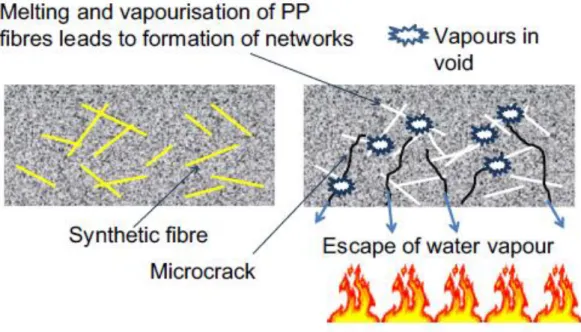
subsequently leading to tensile stress developing in the direction perpendicular to the heated surface Figure 2-12; and (2) the build-up of pressure in the concrete pores as a consequence of the physically/chemically bound water in the cement vaporizing, thereby loading tensile stress in the heated concrete microstructure Figure 2-13. Several studies have examined and found that some combinations of fibres increased the fire-resistance of the HPC. Adding synthetic fibres, especially polypropylene (PP) fibres, to HPC is a widely used and effective method of preventing explosive spalling. Figure 2-14 shows how spalling is reduced when PP fibres are mixed into concrete. Under normal conditions, the PP fibres mixed into concrete exist in a dispersed condition in the concrete. If the concrete surface gets heated during a fire, surface cracking occurs first. Then, as the fire continues to burn, and the temperature of the concrete rises, the free water existing within the concrete turns into vapor, forming vapor bubbles. It is thought that, in the absence of the PP fibres, the vapor pressure within these vapor bubbles results in tensile stress. If the tensile stress exceeds the tensile strength of the concrete, spalling results. However, when the PP fibres are present, they melt at 165–170 _C and form a vapor pressure dissipation network, which effectively dissipates the vapors within the concrete and prevents spalling. (Mitsuo & Hiroaki , 2014)
39
Figure 2-12:Thermal dilation, (Mitsuo and Hiroaki 2014)
40
Figure 2-14: Effect of PP fibres (Mitsuo and Hiroaki 2014)
2.2.1 FRC degradation in elevated temperature
Mechanical properties of steel fibers will decrease by increasing the temperature. An experimental study has been done by Caverzan et all (2015) to investigate the mechanical degradation of fibers when exposed to high behavior of high performance cementitious composite reinforced by microfibers, when exposed to high temperatures. In order to investigate mechanical properties of the fiber at room condition and their decay after a thermal treatment, several steel wires were tested in uniaxial tension. A mix design HPFRCC was used, the mix design is specified in Table 2-4.
Constituent Dosage (kg/m3) Cement type I 52.5 600 Slag 500 Water 200 Super plasticizer 33 l/m3 Sand 0-2 mm 983 Fibers (lf=13mm, df=0.16mm) 100
Table 2-4: Mix design (Caverzan et all 2015)
The high fiber content and the favorable orientation imposed by the casting flow control allowed to guarantee a small dispersion of the response before and after single-crack localization and a hardening behavior in uniaxial tension . (Figure 2-15)
41
Figure 2-15: Slab cast applying a unidirectional flow (Carvezan et all 2015)
In order to investigate mechanical properties of the fibre at room condition and their decay after a thermal treatment, several steel wires were tested in uniaxial tension. Two meter long steel wire samples were cut from a skein (Figure 2-16) used to produce the fibres Uniaxial tension tests.
Figure 2-16:Skein used to produce the fibers (a) (Carvezan et all 2015)
The mechanical strength of the tested specimens are shown in Figure 2-17and Figure 2-18 for temperatures 20, 200, 400 and 600 _C, respectively; The meaning of each parameter is explained as follows:
𝑓𝐼𝑓: First cracking strength, representing the matrix flexural tensile strength, is the maximum strength in the COD range 0–0.1 mm. Due to the hardening behavior in bending
42
after first cracking, the maximum value, in the investigated range, is always considered, and it is referred to as 𝑤1;
𝑤1 : Conventional COD when the first crack is assumed to propagate;
𝑓𝑒𝑞1: Average nominal strength in COD range between 3wI and 5wI (0.3–0.5 mm)
that is considered as a reference for Serviceability Limit State (SLS) residual strength; 𝑓𝑒𝑞2: Average nominal strength in COD range between 0:8wu and 1:2wu, which is
regarded as ultimate limit state (ULS), when material behavior is governed only by pull-out mechanism.
43
Figure 2-17: Stress versus COD curves. Tests carried out on an undamaged specimens 20C; b specimens exposed up to 200 C
44
Figure 2-18: Stress versus COD curves. Tests carried out on: a specimens exposed up to 400 C; b specimens exposed up to 600 C (Carvezan et all 2015)
Finally, on the basis of the equivalent strengths, defined by taking into account the pre-peak ductility, it is possible to show that the residual equivalent strengths change with the increase in temperature (Figure 2-19) differently from steel fiber reinforced concrete characterized by a low content of fibers (0.7 %). The comparison clearly highlights the surprising performances of such materials in terms of its fire resistance behavior.
45
Figure 2-19: Residual strengths versus temperature for SFRC and HPFRC feq1(T)/feq1(20) versus temperature (a); feq2(T)/feq2(20) versus temperature (b)
46
Figure 2-20: Fracture surfaces on specimen exposed to a thermal cycle up to 600 C; fibers failed (a), Pulled out (b)
The type of fiber failure shows a significant ductility up to 400 _C and the ratio between feq2 and feq1 confirms the hardening in bending definition (feq2/feq1 = 1.66). The
material exposed to 600 C fails due to steel fiber rupture, this behavior being prevailingly due to the damage caused to the fibers by the high temperature. Thermal treatment up to 600 C was shown in Figure 2-20. The significant decay of the fibers mechanical properties can be ascribed to the change in the fiber microstructure and an evident reduction of the cross section. Moreover, fibers exposed to 600 C appear covered by an oxide film, which could affect the bond between the fibers and the matrix. (Caverzan, Colombo, Di Prisco, & Rivolta, 2015)

![Figure 4-8: Thermal conductivity of HPC and comparison with NC 00.511.522.5020040060080010001200 1400conductivity]temperature ['C]Thermal Conductivity HPCNC lower limitNC upper limit](https://thumb-eu.123doks.com/thumbv2/123dokorg/7514819.105542/79.892.145.742.752.1103/figure-thermal-conductivity-comparison-conductivity-temperature-thermal-conductivity.webp)