POLITECNICO DI MILANO
SCUOLA DI INGEGNERIA INDUSTRIALE E DELL’INFORMAZIONE
Dipartimento di Elettronica, Informazione e Bioingegneria Laurea Magistrale in:
Ingegneria Biomedica - Biomeccanica e Biomateriali
An experimental apparatus for
isolated contractile hearts from
abattoir swines
Relatore:
Prof. Riccardo VISMARA Correlatori:
Prof. Gianfranco Beniamino FIORE Dott. Michał Lukasz JAWOREK Dott. Federico LUCHERINI
Tesi di laurea di: Giulia PARIGI 837129 2017 - 2018
Contents
1 Introduction 20
2 Anatomy and physiology 23
2.1 Anatomical structure of the heart . . . 23
2.2 Electrical conduction system of the heart . . . 25
2.3 Physiology . . . 27 2.3.1 Cardiac cycle . . . 28 2.3.2 PV loop . . . 29 2.3.3 Frank-Starling mechanism . . . 31 2.3.4 Guyton’s model . . . 32 2.4 Blood . . . 33
3 State of the art and project specifications 35 3.1 Harvesting . . . 35
3.2 Cardioplegia . . . 36
3.3 Perfusate . . . 37
3.4 Langendorff reperfusion . . . 39
3.5 Hydraulic circuit components . . . 40
3.5.1 Afterload . . . 40
3.5.2 Oxygenator and heat exchanger . . . 41
3.5.3 Preload . . . 42 3.5.4 Arterial filter . . . 42 3.6 Working mode . . . 43 3.7 Obtained results . . . 44 3.8 Project specifications . . . 45 4 Materials ad methods 49 4.1 Afterload . . . 49
4.1.1 Lumped parameters model . . . 49
4.1.3 Dimensioning and manufacturing . . . 51
4.1.4 Experimental afterload tests . . . 58
4.2 Platform configuration . . . 60
4.2.1 Connectors and instrumentation . . . 63
4.3 Preliminary tests . . . 67
4.3.1 Blood management test . . . 67
4.3.2 Training tests . . . 67
4.4 Harvesting protocol . . . 67
4.5 Beating heart protocol . . . 69
5 Results and discussions 72 5.1 Afterload . . . 72
5.1.1 Characteristic resistance . . . 72
5.1.2 Peripheral resistance . . . 73
5.1.3 Tests with biological samples . . . 75
5.1.4 Lumped parameters model . . . 77
5.2 Preliminary tests . . . 78
5.2.1 Training tests . . . 78
5.2.2 Blood management test . . . 78
5.3 Beating heart test . . . 79
Estratto
Introduzione
Le malattie cardiovaliscolari sono una delle cause maggiori di morte in Europa. Le tec-niche per trattare queste particolari malattie (sia farmacologiche che basate sull’utilizzo di dispositivi) sono in continuo sviluppo. Per poter effettuare affidabili test preclinici delle nuove tipologie di trattamento e limitare la sperimentazione animale, è neces-sario sviluppare modelli cardiovascolari realistici. Questi modelli possono avere diversi impieghi. Ad esempio, possono essere usati per lo sviluppo di nuove procedure chirur-giche, per effettuare test che valutino la funzionalità di nuovi dispositivi o, addirittura, come dispositivo medico per il trapianto di organi. Essi sono classificabili in quattro gruppi: modelli animali, duplicatori di impulsi, sistema a cuore pulsante passivo e sistema a cuore pulsante isolato. Lo scopo di questo lavoro di tesi, sviluppato in col-laborazione con il laboratio ForcardioLab, è di sviluppare un sistema a cuore pulsante isolato utilizzando un cuore di suino proveniente da macello. In questa tipologia di ap-parato, il sistema cardiovascolare viene simulato con un opportuno circuito idraulico, mentre il cuore si contrae autonomamente, come se fosse ancora in vita.
Materiali e metodi
Postcarico
È stato sviluppato un sistema di post-carico in grado di riprodurre l’impedenza sistem-ica. Il post-carico è stato progettato come rappresentazione idraulica di un modello a parametri concentrati a tre elementi: una resistenza caratteristica, una compliance e una resistenza periferica. I componenti idraulici sopra elencati sono stati progettati e costruiti per soddisfare i valori presenti in letteratura. Il post-carico è stato proget-tato per essere compatto e modulare, ed è composto da cinque parti (fig. 1) connesse tramite flange. Ogni parte può essere sostituita per ottenere diversi valori di resistenza. La resistenza caratteristica è stata ottenuta con 588 tubi da 1 mm di diametro e
Figure 1: Post carico
utilizzando l’equazione di Poiseulle’s (eq. 1) Rbundle =
128 ∗ µ ∗ L
n ∗ pi ∗ D4 (1)
in cui µ è la viscositò del sangue, L è la lunghezza dei tubi, n è il numero di tubi,
Dè il diametro interno di ogni tubo.
La compliance è stata simulata tramite un serbatoio chiuso posto a pressione at-mosferica. Il volume di aria iniziale richiesto è stato di 3 litri, ottenuto dalla equazione 2
V0 = −k ∗ C ∗
P2 e
P0 (2)
in cui V0è il volume di aria iniziale, C è la compliance, Peè la pressione di esercizio e P0è
la pressione atmosferica. L’approccio analitico presuppone l’approssimazione dell’aria a gas ideale e considera le trasformazioni termodinamiche isoterme ed adiabatiche. La compliance è stata realizzata in due compartimenti: uno incluso nel post-carico, di piccolo volume, e l’altro, di maggior volume, posto a distanza e connesso al post-carico. La resistenza periferica è stata ottenuta con componenti di forma conica e cilindrica, posizionati all’interno di elementi di forma complementare. (fig 2).
Il fluido scorre nell’intercapedine tra l’elemento esterno e quello interno. Lo sposta-mento coassiale della parte interna rispetto all’esterna permette di cambiare la distanza tra le due superfici, quindi la resistenza (fig. 3).
con-Figure 2: Resistenza periferica
Figure 3: Regolazine della resistenza periferica
dizioni di ipertensione, ipotensione e normotensione utilizzando l’equazione modificata di Poiseuille per condotti anulari (eq.3) (lo spazio tra la parte interna ed esterna è stato modellizzato come una serie di condotti anulari di lunghezza infinitesima, contribuendo insieme al valore di resistenza totale):
Ran.cond. = ∆P Q = 8 ∗ µ ∗ dl pi ∗ (r2 e− ri2) ∗ [(re2+ ri2− r2 e−r2i log(reri))] (3) dove µ è la viscosità del fluido, Q è il flusso, dl è la lunghezza dei condotti, re e ri sono, rispettivamente, il raggio esterno ed interno.
Il meccanismo che permette di cambiare la distanza dei due componenti è basato su una sistema vite-madrevite. Questo rende il sistema di post-carico estremamente versa-tile. I risultati analitici ottenuti durante il dimensionamento del post-carico sono stati confrontati con quelli ottenuti da test sperimentali in condizioni di flusso stazionario. Campioni biologici sono stati invece utilizzati per test sperimentali in condizioni di flusso pulsatile, permettendo l’identificazione delle condizioni di lavoro del post-carico. Configurazione del sistema
Lo schema del circuito utilizzato negli esperimenti con cuore pulsante isolato è mostrato in figura 4. È composto da 5 sotto-circuiti con funzioni specifiche:
• Circuito di ossigenazione (rosse e verde): è composto da due percorsi differenti. Entrambi ricircolano il sangue attraverso l’ossigenatore - scambiatore di calore (OXY) e il filtro arterioso (F) dai serbatoi venosi (RES,PL).
Figure 4: Schema del circuito per il cuore battente isolato
lavoro prima che il cuore fosse collegato al sistema.
• Circuito di Langendorff (blu): è stato usato nella procedura di rianimazione del cuore grazie alla perfusione coronarica.
• Circuito di recupero (nero): è stato usato per recuperare il sangue uscente dai seni coronarici, che è stato riportato al pre-carico.
• Circuito di lavoro (giallo): permette la normale circolazione: dal pre-carico, al cuore, al post-carico. Questo circuito è stato usato solo dopo aver recuperato la contrattilità miocardica a seguito della procedura di Langendorff.
Test preliminari
Sono stati effettuati degli esperimenti preliminari per acquisire manualità con il sistema e con la gestione sangue.
Il sangue è stato trattato con 5000 UI/l di eparina per evitare la coagulazione. Suc-cessivamente, è stato filtrato e fatto circolare nel circuito di ossigenazione. Sono state sperimentate quattro differenti miscele di aria e anidride carbonica per l’ossigenazione, ed è stata monitorata la concentrazione di ossigeno.
In aggiunta, sono stati effettuati tre esperimenti preliminari per permettere ad ogni membro del gruppo di acquisire familiarità con il sistema e con la procedura di labo-ratorio. Anche i chirughi hanno partecipato agli esperimenti preliminari.
Protocollo di espianto
1. Espianto, somministrazione della soluzione cardioplegica e trasporto: Dopo la rimozione degli organi interni dell’animale, i chirughi hanno separato il cuore dai polmoni. Successivamente, il cuore è stato lavato in una soluzione salina con aggiunta di eparina. La soluzione cardioplegica di St. Thomas è stata iniettata nelle coronarie e il cuore è stato immerso in un contenitore riempito con ghiacchio e soluzione cardioplegica per il trasporto.
2. Prelievo e trasporto del sangue: sono stati prelevati 10 litri di sangue da di-versi animali, raccolto in taniche preventivamente eparinizzate. Il sangue è stato trasportato in laboratorio prima del cuore per snellire le procedure in laboratorio. Protocollo per il cuore battente
1. Ossigenazione del sangue: il sangue è stato ossigenato e scaldato usando l’apposito circuito di ossigenazione. Il pH è stato controllato e portato entro i limiti.
2. Preparazione del lavaggio delle coronarie riempimento del circuito: la linea blu è stata riempita con soluzione salina in preparazione al lavaggio coronarico. Succes-sivamente, il circiuto è stato riempito con il sangue precedentemente ossigenato. 3. Preparazione del cuore: il cuore è stato preparato inserendo i connettori aortico
ed atriale, che hanno permesso il collegamento del cuore al circuito.
4. Lavaggio delle coronarie: le coronarie sono state lavate con la soluzione salina precedentemente preparata (punto 1) per eliminare i residui della cardiolplegia. Questo è stato fatto con una pressione di perfusione di 100mmHg.
5. Perfusione di Langendorff : La perfusione di Langendorff è stata condotta con il sangue ad una pressione di 100mmHg per 5 minuti, fino a che il cuore non ha mostrato le prime contrazioni. A questo punto, l’ossigenazione è stata spostata sulla linea verde.
6. Modalità operativa: dopo che il cuore ha iniziato a contrarsi, è stato aperto il circuito per la normale modalità di lavoro.
Risultati
Caratterizzazione del post-carico in condizioni di flusso stazionario
e pulsatile
In fig.5 vengono mostrare le curve di pressione-flusso per la resistenze caratteristica: la blu è quella ottenuta dalla soluzione analitica mentre la rossa è il risultato di test sperimentali.
Figure 5: Resistenza caratterisctica: curva pressione-flusso
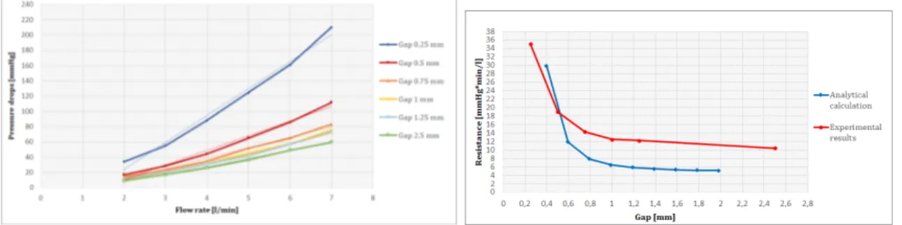
Il trend è lineare ed il valore di resistenza predetto dalla soluzione analitica è ac-curato. Fig.6 mostra i risultati sperimentali per la resistenza periferica. A sinistra le curve di pressione-flusso per flussi da 2 l/min a 7 l/min, a destra la curva di resisteza-intercapedine per i risultati analitici e sperimentali.
Figure 6: Resistenza periferica: curva flusso-pressione (sinistra) e resistenza-intercapedine (destra)
La relazione tra pressione e flusso è lineare nell’intervallo considerato. Si nota che i calcoli analitici sottostimano i valori di resistenza.
Il valore di resistenza ottenuto per la resistenza caratteristica è stato di 0.9 mmHg*min/l, in linea con quello desiderato. L’intervallo ottenuto per la resistenza periferica è stato tra 10 e 35 mmHg*min/l, il quale include il valore desiderato di 16 mmHg*min/l.
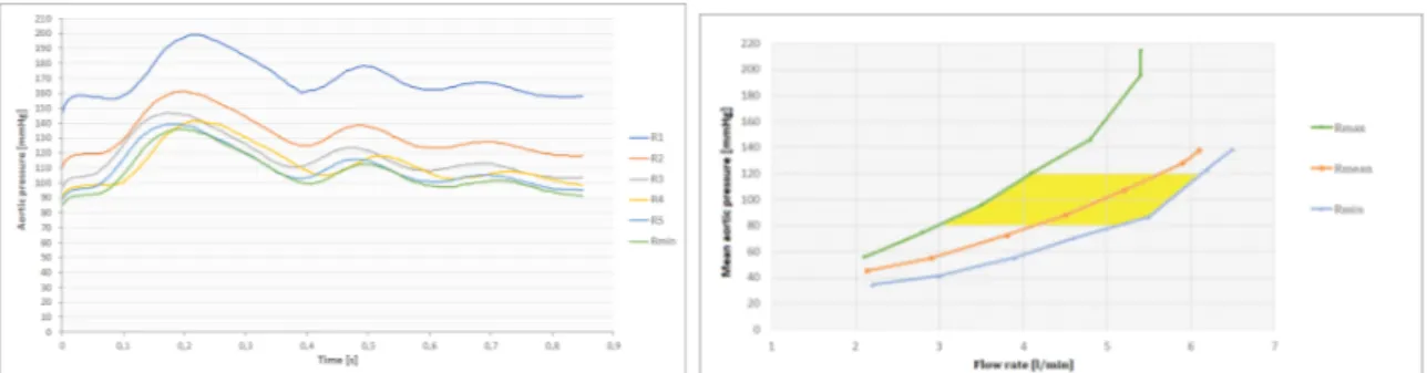
Nella figura 7 sono mostrati i risultati dei test condotti su camponi biologici azionati dal sistema pompante esterno. A sinistra vengono illustrate le curve di pressione aortica per diversi valori di resistenza. Gli esperimenti sono stati effettuati a 70 bpm e 94 ml di
Figure 7: Curve di pressione in test con flusso pulsatile (sinistra) e range di lavoro (destra)
volume sistolico. Le pressioni ottenute sono maggiori di quelle attese, ma nel normale regime fisiologico. Nella figura 7, a destra, sono mostrate le curve di pressione-flusso medi, ottenute variando la frequenza del sistema pompante. Il post-carico è risultato essere versatile in quanto un vasto range di condizioni di lavoro è stato simulato con successo.
Tests preliminari
Il contenuto di ossigeno in condizioni di ossigenazione nulle aveva un valore di 8.6e ha raggiunto la sua massima concentrazione dopo 6 minuti di ossigenazione. Gli es-perimenti preliminari sono stati effettuati con successo. Il sistema è stato perfezionato ed il protocollo ottimizzato. Tutti i componenti del gruppo hanno acquisito sicurezza nella gestione del sistema e nelle procedure di laboratorio.
Test con cuore battente
Durante gli esperimenti con il cuore pulsante, il cuore era a 36° C ed aveva un pH di 7.52. La perfusione di Langendorff è stata effettuata a 100 mmHg per 5 minuti. Successivamente, il cuore ha iniziato a contrarsi spontaneamente, e ciò è durato per circa 6 minuti. Quando si è passati dalla perfusione di Langendorff alla modalità operativa, il cuore ha iniziato ad indebolirsi ed ,infine, si è fermato.
Conclusioni
L’obbiettivo di questo lavoro di tesi è stato la realizzazione di un sistema per un cuore pulsante isolato. Il sistema è stato progettato per ospitare cuori suini proveniente da mattatoio, usando il sangue come fluido di lavoro. Per quanto riguarda la realizzazione del post-carico, è stato ideato un dispositivo modulare, compatto e facilmente utiliz-zabile. L’intervallo di valori di resistenza desiderato è stato ottenuto con successo e
la relazione pressione-flusso è risultata lineare. Gli esperimenti con i campioni bio-logici hanno dimostrato la versabilità del post-carico. Infatti, grazie alla possibilità di variare la resistenza, è stato simulato un vasto range di condizioni di lavoro . Alcune migliorie possono essere introdotte per migliorare la linearità tra la resistenza ottenuta ed il sistema di regolazione. Un possibile sviluppo futuro riguarda lo studio degli ef-fetti emolitici del post-carico. L’apparato sviluppato ed il protocollo ideato sono stati efficenti. Per quanto riguarda il primo esperimento effettuato sul cuore pulsante, due problematiche sono state individuate: la prima sulla perfusione di Langendorff, che è stata effettuata in maniera troppo rapida, avendo reso impossibile il rafforzamento del cuore. La seconda riguardava il settaggio del post-carico nel passaggio da Langen-dorff alla condizione di lavoro: infatti la pressione fornita è risultata troppo bassa per stimolare il cuore a riprendere il ritmo sinusale. Il sistema presentato in questo la-voro sarebbe adatto per supportare la sperimentazione di nuove procedure chirurgiche non-invasive, che stanno sempre più crescendo ed evolvendosi.
Abstract
Introduction
Cardiovascular diseases are one of the main causes of death in Europe. Their treat-ments (both pharmacological and device based) are under constant development. To enable reliable preclinical testing of new treatments and limit animal testing, realistic models of the cardiovascular system are needed. They can be employed e.g. for clini-cians training in new surgical procedures, for assessment of new device functionalities or even become a medical device itself (as for organ transplantation). They can be clas-sified into four groups: animal models, simple pulse duplicators, passive beating hearts systems and isolated beating hearts systems. The aim of this work of thesis, carried on in collaboration with ForcardioLab, is to develop an apparatus to house isolated beating heart coming from abattoir swines. In this kind of apparatus, cardiovascular system is simulated by hydraulic circuit, and housed hearts contract independently, as they were still alive.
Material and methods
Afterload
An afterload system that reproduced the systemic impedance was developed. It was designed as an hydraulic representation of a three-element lumped parameters model, with characteristic resistance, compliance chamber and peripheral resistance. These hydraulic components were designed and manufactured in order to meet the target values derived from literature. The afterload is compact and modular. Indeed it is composed by five parts (shown in figure 8) connected by flanges. Every part can be substituted if necessary, to assume different resistance ranges.
The characteristic resistance was realised with 588 1 mm-diameter-tubes with 40 mm of length, gathered into a PMMA collector. Resistance was dimensioned using
Figure 8: Afterload
Poiseuille’s equation (eq. 4)
Rbundle =
128 ∗ µ ∗ L
n ∗ pi ∗ D4 (4)
where µ is blood viscosity, L the length of the bundle, n the number of tubes, D the internal diameter of each tube.
The compliance was simulated by close to atmosphere reservoir. The required initial air volume of 3 liters derived from equation 5
V0 = −k ∗ C ∗
P2 e
P0
(5)
where V0 is the initial air volume, C the compliance, Pe the exercises pressure and
P0 the atmospheric pressure. This analytical approach approximates the air as an
ideal gas and consider isothermal and adiabatic thermodynamic transformations. The compliance was realized in two compartments: low volume that was included in the afterload and a second high voulume placed distally.
The peripheral resistance was manufactured as conical and cylindrical components, placed inside their complementary parts (fig. 9). The fluid flow was forced between the internal and the external element. The coaxial displacement of the internal part with respect to the external one enabled changing the gap between the two surfaces, thus
Figure 9: Peripheral resistance
varying the resistance (fig. 10). It was analytically dimensioned to imitate resistance
Figure 10: Regulation of the peripheral resistance
range corresponding to hypertensive, hypotensive and normotensive conditions, using modified Poiseuille equation for annular conduits (the space between the internal and external components was divided into annular conduits and the contribution of each conduit to the resistance was summed up):
Ran.cond. = ∆P Q = 8 ∗ µ ∗ dl pi ∗ (r2 e− ri2) ∗ [(re2+ ri2− r2 e−r2i log(reri))] (6)
where µ is the viscosity of the fluid, Q is the flow, dl is the length of the conduits, re
and ri the external and internal radius respectively.
The resistance regulation system providing the coaxial displacement of the internal part in respect to the external part was based on screw mechanism. This provided the versatility of the afterload system.
Characterisation tests of the afterload were carried out in steady flow to validate the analytical results. Tests in pulsatile regime with biological samples were performed to identify afterload limit working conditions.
Platform configuration
In figure 11 the schematic view of a circuit for performing isolated beating heart ex-periments is shown. It is composed by 5 sub-circuits with different specific functions.
• Oxygenation circuit (red and green): it is divided into two different path. Both of them recirculate the blood through oxygenator - heat exchanger (OXY) and
• Filling circuit (orange): it was used to initially fill the working mode lines when the heart was not present.
• Langendorff circuit (blue) : it was used in the resuscitation procedure, when just the coronaries were perfused.
• Recirculation circuit (black): it was used to recirculate the outflow from coronary sinus back to the preload reservoir.
• Working mode circuit (yellow): it enabled blood pumping by the heart itself from preload to the afterload. This circuit was used after successful Langendorff reperfusion.
Figure 11: Schematic view of the beating heart apparatus
Preliminary tests
Preliminary tests to get experience in blood management and apparatus handling were performed.
During collection, blood was treated with 5000 UI/l of heparin to avoid coagulation. Afterwards, the blood was filtered and recirculated in the oxygenation circuit. pH was measured for four different gas mixture and the oxygen content was monitored. Three training tests were performed to allow every team member to get familiar with the apparatus and with laboratory protocol. Surgeons were involved in these tests.
Harvesting protocol
1. Harvesting procedure, cardioplegic solution’s administration and transportation: after the butcher removed the internal organs from the animal, surgeons started to dissect the heart from lungs. Afterwards, heart was washed in heparinised saline solution. St Thomas cardioplegic solution was injected in the coronaries and the heart stored in ice and cardioplegic solution for the transportation. 2. 10 l of blood were collected from different pgs using heparinised tanks.It was
brought to the laboratory in advance in respect to excised heart to accelerate the procedures in laboratory.
Beating heart protocol
1. Blood oxygenation and rewarming: blood was oxygenated and rewarmed through the circulation in the red circuit. pH was measured and adjusted o have a value among 7.3 and 7.5
2. Preparation for wash out and circuit filling: the blue line was filled with saline solution to be ready for the wash out procedure. Then the circuit was filled with previously oxygenated blood.
3. Heart’s preparation: the heart was prepared: aortic and atrial connector were inserted to house it in the apparatus
4. Coronaries wash out: the coronaries were washed out from the cardioplegic so-lution with the saline previously prepared in the blue line. Pressure was kept at 100 mmHg and leakages thrown away.
5. Langendorff reperfusion: Langendorff reperfusion started with blood. Pressure was kept at 100 mmHg for 5 minutes, till the heart recovered contractility. Oxy-genation was switched to the green circuit.
6. Working mode: after the heart started contract, the Langendorff perfusion was switched into working mode.
Results
Afterload characterisation in steady flow and pulsatile conditions
Figure 12: Characteristic resistance: pressure-flow curve
value predicted by analytical calculation accurate. Fig. 13 shows the experimental pressure-flow curve for peripheral resistance within a range of 2 - 7 l/min and the resistance - gap curve for analytical calculation and experimental tests. The pressure-flow relationship was linear in the considered range. Analytical calculation underes-timated the resistance values. Resistance value for characteristic resistance was 0.9
Figure 13: Conical and cylindrical peripheral resistance: pressure-flow curve and resistance-gap
curve
mmHg*min/l, in line with target value. The range obtained for the peripheral re-sistance was between 10 and 35 mmHg*min/l, that includes the target value of 16 mmHg*min/l.
In figure 14 aortic pressure curves measured for different resistances during pulsatile test with biological sample actuated by external pumping system are shown. Test were performed at 70 bpm and 94 ml of stroke volume. Pressures were higher than expected, but in physiological normal ranges. In figure 14 the pressure-flow curves obtained with mean pressure and flow values illustrates the working condition of the afterload. It turned out to be versatile.
Preliminary tests
During blood management tests, pH values for different gas mixture were measured. The results are summarised in table 1.
Figure 14: Pressure curves in pulsatile test with biological sample for different resistances
Table 1: Ph measurements
Air[l/min] CO2 [l/min] pH
0 0 7.58
8 0.5 7.63
7 0.5 7.52
5 0.5 7.44
Oxygen content started from a value of 8.6and reached the maximum concentration within 6 minutes of oxygenation.
The training tests were successfully conducted. The apparatus was ameliorated and the protocol optimised. All the members of the team gain awareness of the laboratory procedures.
Beating heart test
During the beating heart test blood was at 36℃and had a pH of 7.52. Langendorff reperfusion was performed at 100 mmHg for 5 minutes. At that point, heart showed spontaneous contractions that lasted about 6 minutes. When the passage from Lan-gendorff to working mode was performed, the heart started weakening and stopped.
Conclusions
This work was focused on the realisation of an apparatus for isolated beating heart. The apparatus was designed to house swine hearts from abattoir, with the use of blood as working fluid. Concerning the afterload realisation, a compact, user friendly and modular device was manufactured. The target resistance range was achieved and the pressure - flow relationship was linear. Tests with biological samples demonstrate the versatility of the afterload. Indeed, thanks to the adaptability of the resistance, a large
variety of working conditions were reproduced. Possible amelioration concerns the improvement of linearity between the achieved resistance and the regulation system. A possible future development consists in the study of haemolitic effect of the afterload. Developed apparatus and established protocols were effective and did not generate any kind of issue. Regarding the first beating heart test, two pitfalls were identified. One concerning Langendorff perfusion, that was to rapid, avoiding heart strengthening. The other regarding afterload setting in the passage from Langendorff to working mode, that did not provide enough pressure.
Chapter 1
Introduction
Nowadays cardiovascular diseases (CVDs) are one of the main causes of death in Eu-rope. A large variety of pathologies are included in this big category, both of vascular and cardiac nature. Just to mention few, ischaemia and stroke for the first class, cardiomyopathy, valvular diseases and inflammatory diseases for the second one[18]. Depending on singular cases, some of them can lead to death, but some others can be nursed by surgical procedures, structure’s repair or substitution (as in the case of valve disease) or even by transplants. All of this solutions are in constant development to become more and more effective, and many researches have been carried out.
On this background rises the need of systems helping clinicians and engineers in the achievement of maximum results, as improvement of treatments, training procedures or better understanding of cardiac diseases. These kind of systems are required to reproduce human cardiovascular system (or its part) and provide feedback by mean of hemodynamic (e.g. flow rate, aortic pressure) and physiologic (e.g. strength developed by myocardium, cardiac work, cellular metabolism) measures and visual information (direct visualization, medical imaging e.g. echocardiography, CT). In the available literature one can distinguish four type of solutions, described here below.
1. Animal models: tests are conducted on living animals. They can be small animals like mince or rabbits if drug testing or assessment of cardiac functionalities are investigated. For cardiovascular device testing instead, bigger animals are em-ployed, as ship or pigs ([2]). The advantage is that heart is intact and in normal physiological environment. On the other side, they have important limitations as inadequate experiments reproducibility, difficult control of variables of interest and high costs.
2. Simple pulse duplicator: It is an in-vitro hydraulic circuit, where the vasculature is represented by a RCR hydraulic component and the flow is provided by a
pulsatile pump. Heart model used in these systems is artificial, made of silicon or soft materials [9], [25]. They provide good controllability of the fluid dynamics but they lack in precise anatomical reproduction.
3. Passive beating hearts: it is a hydraulic circuit simulating cardiovascular system where an animal ([14]) or human [19] heart can be housed. The heart sample has lost the natural contractile properties, but instead it is actuated by an ex-ternal pulsatile pump. Usually big animals hearts are used, as pigs, since their anatomy is similar to human one. For this reason they are advantageous for tests in which anatomical structures are important, such as kinematic analysis of valvular leaflets or surgeons training for innovative procedures. Physiologi-cal and pathologiPhysiologi-cal fluid dynamic conditions can be reproduced. However, this kind of models lack physiological-like interventricular flows and autoregulation mechanisms (e.g. Frank-Starling mechanism, vascular regulation).
4. Active beating hearts: this apparatus is similar to the passive beating heart ap-paratus, but hearts contracts independently, as they were still alive, without any help of external pumping systems([12][7]). The organs are harvested from a donor animal, stored in cold solutions to avoid cell damages, and then they are resusci-tated through a procedure, invented by Oscar Langendorff, that consists in the hemoperfusion of the coronaries retrogradely through the aorta. After this, the contractile function is restored and the heart starts beating by itself.
The presented approaches in modelling of cardiovacular system demonstrate different levels of similarity, complexity, controllability over the experiment and repeatibility. Among the presented approaches, the animal model is the most complex, the least controllable and repeatable but the most realistic one. Whereas simple pulse dupli-cator is the most controllable, repeatable and simplest but is the least realistic one. Among presented models active beating heart model has a unique feature to be able to capture the complexity of the real system but eliminating the unwanted influence ("noise") of the other physiological systems of the human body (more controllable than aminal model).
This apparatus can be used for various purposes. Originally it was used to study con-tractile function and measure coronary flow by Langendorff. Then this setup helped in discovery of autoregulatory mechanims of the heart (Frank-Startling mechanism). Currently, it is used mainly in pharmacological studies, where small aminal hearts are used (e.g. mouse or rabbit). Some researchers, which work will be explained in details in the next chapter, employed such a system to test LVAD [16][1][11], some others for kinematic studies [3].
Finally, it can be useful also in transplantation field. Heart transplants nowadays are a very problematic procedure: first of all because of lack of donors, secondary because the time over which an heart can survive after the harvesting without consistent damages is limited to 4-5 hours, during which complications arise anyway in many cases. This largely affects the geographic area that can be covered by a single organ for obvious issues in transportation. This time can be extended if the explanted heart is kept beat-ing until it is delivered to the transplant centre. It can be achieved by applybeat-ing active beating heart concept. An example of this, is the "OCS heart" [23] (fig.1.1) developed by TransMedics: the product has succeed in phase 2 of FDA clinical trial, conducted between 2013 and 2015, and is currently under phase 3 studies. In the phase 2 clinical trial 130 patients that needed heart transplantation were randomly treated with OCS new technology or with standard procedures. The outcomes of the transplantations in the two groups were evaluated and compared, and the OCS system gained a patient and graft survival rate after 30 days of 94(97for standard cold storage group) and 13patients with cardiac-related serious adverse events (14for standard cold storage group). [4]
The present work of thesis, developed in collaboration with ForcardioLab, inserts in this context. In fact the main goal was to develop an isolated active heart apparatus for medical device testing and surgeons training.
Chapter 2
Anatomy and physiology
2.1
Anatomical structure of the heart
The heart is the central organ of human body. It is located in the middle of the chest, behind and slightly on the left of the sternum. Its dimensions are variable between 9-10 cm wide, 13-15 in length and its weigh is between 280 and 340 g in male and 230-380 g in female.
Heart function is the one of a pump: it fills passively and contracts to confer to the blood the necessary amount of energy to circulate in the body.
Externally, the heart is protected by a double-walled sac called pericardium. This sac protects the organs and is responsible of the anchoring of it inside the rib cage. The surface of the heart is composed by a three layers wall: the outer epicardium, the middle myocardium and the inner endocardium. The epicardium is composed by connective tissue and protects the heart. The myocardium consists mostly on cardiac muscle tissue and a net of blood capillaries and nerve fibres. It is the responsible of contractions. The endocardium is made up of epithelium and connective tissue, with collagenous fibres and blood vessels. It covers the internal cavities and the valves. Moving to the internal part, it is possible to distinguish four chambers: two on the left side and two on the right side (Fig.2.2). The upper chambers are called atria, and they are separated each other by a wall-like membrane called interatrial septum. The lower chambers are called ventricles, and they are separated by the interventricular septum. Atria and ventricles are connected through valves, that passively open and close by pressure gradient. The mitral valve on the left side and the tricuspid valeve on the right side. Other two valves are placed at the outlet of the ventricles, the pulmonary
valve to the right and the aortic valve to the left. Both atria and ventricles are
con-nected to large vessels, carrying blood in and out the chambers. On the right side the two venae cavae, superior and inferior, enter in the right atrium, carrying blood coming
Figure 2.1: Internal anatomy of the heart
from body districts. Left and right pulmonary arteries exit from the right ventricle and connect it to the lungs. On the left side, left and right pulmonary veins carry blood from lungs to the left atrium. The aorta exits from the left ventricle and transports blood to all body districts.
Coronaries The heart itself needs nutrients and oxygen: this is supplied by coronary
circulation. It is articulated in arteries, arterioles, capillaries, venules and veins, with diameter going from few millimetres to less than 300µm. The coronary arteries take origin in the aortic root, from the left posterior aortic sinus and the anterior sinus. They give origin to the left coronary artery and to the right coronary artery respectively. With their branches, they lie on the surface of the heart and perfuse the whole muscular tissue. From the tissue, the coronary veins drain blood into the right atrium.
2.2
Electrical conduction system of the heart
Macroscopic level
The contraction of the heart muscles is ensured by an articulate electrical conduction system. It is composed by nodes and fibres, namely the sinoatrial node (SN), the atri-oventricular node (AV), the bundle of His and the Purkinje fibers.
A heart nodes are specialized type of tissue that behaves as both muscle and nervous tissue. When nodal tissue contracts, it generates nerve impulses that travel throughout the heart wall. The sinoatrial node, also referred to as the pacemaker of the heart, coor-dinates heart contractions. Located in the upper wall of the right atrium, it generates nerve impulses that travel throughout the heart wall causing both atria to contract. The SA node is regulated by autonomic nerves of the peripheral nervous system. The
atrioventricular node lies on the right side of the partition that divides the atria, near
the bottom of the right atrium. When the impulses generated by the SA node reach the AV node, they are delayed for about a tenth of a second. This delay allows atria to contract, thereby emptying blood into the ventricles before ventricular contraction. The AV node then sends the impulses down the atrioventricular bundle to the ventri-cles. The regulation of electrical signals by the AV node ensures that electrical impulses do not move too rapidly, which can result in atrial fibrillation.
Impulses from the AV node are passed along to atrioventricular bundle fibers. The atrioventricular bundle, also called the bundle of His, is a bundle of cardiac muscle fibers located within the septum of the heart. This fiber bundle extends from the AV node and travels down the septum. The atrioventricular bundle splits into two bundles near the top of the ventricles and each bundle branch carry impulses to the left and right ventricles.
Purkinje fibersare specialized fiber branches found just beneath the endocardium of the
ventricle walls. These fibers extend from atrioventricular bundle branches to the left and right ventricles. Purkinje fibers rapidly relay cardiac impulses to the myocardium of the ventricles causing both ventricles to contract.
Microscopic level
Two types of cells can be distinguished concerning electrical system of the heart. Cells of the SA and AV nodes are pacemaker cells since they spontaneously generate action potentials. The other cells of myocardial tissue generate action potentials only when stimulated. Action potentials of both are shown in figure 2.3.
The action potential in the pacemaker cells can be divided in 3 phases.
Figure 2.3: Left: action potential of pacemaker cell (node cells). Right: action potential of non-pacemaker cells (myocardial cells)
especially Ca++. The membrane potential slowly rises from -60 mV to -30/-40 mV, reaching threshold level, when phase 2 starts.
Phase 2: A more rapid depolarisation take place due to increasing Ca++ inward
cur-rents, till the membrane potential become positive.
Phase 3: Channels for K+ opens producing outward K+ currents, while the inward
Ca++ currents decrease: the cell repolarizes and the membrane potential come back to -60 mV.
The action potential in the myocardial cells can be divided in 4 phases.
Phase 1: K+ channels are open and the current is outward, keeping the membrane
potential around -70 mV. When a stimulus arrive, phase 2 begins.
Phase 2: K+ channels close and Na+ channels open, producing inward current of Na+.
When membrane potential become positive, phase 3 starts.
Phase 3: K+ and Ca++ channels open, the resulting current makes the membrane
potential slowly decrease, creating a plateau.
Phase 4: more K+ channels open while Ca++ channels close: outward K+ currents
repolarize the membrane.
The difference between the two action potentials is related to ions current and channels speed. Indeed for pacemaker cells the driving current is the Ca++ current, while for non-pacemaker cells it is Na+ current. Moreover, the depolarisation phase (phase 2) is much slower in pacemaker cells than in non-pacemaker ones: this because of the kind of channels activated. It is important to underline that the hyperpolarisation phase (phase 3) is necessary for pacemaker channels to become activated. Without mem-brane potential become very negative, the channels would remain inactivated, blocking spontaneous generation of action potential.
2.3
Physiology
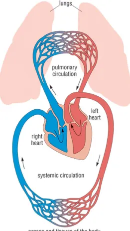
There are two circulation in the heart: the pulmonary circulation and the systemic circulation.
The pulmonary circulation is the one dedicated to oxygenate the blood coming from body districts. It takes place between right ventricle and left atrium. Blood is ejected by the right ventricle to the pulmonary arteries and reach the lungs. In the lungs gas exchange occurs, and the blood enriches of oxygen and release carbon dioxide. From the lungs it passes through pulmonary veins and reach the left atrium.
The systemic circulation is the one that supplies oxygenated blood to the tissues. It takes place between left ventricle and right atrium. From the left ventricle the blood is ejected into the aorta and reaches all the body districts. Then venae cavea collects de-oxygenated blood from all over the body and carries it into the right atrium.
2.3.1
Cardiac cycle
The cardiac cycle is the sequence of events that occurs when the heart beats. As the heart beats, it circulates blood through pulmonary and systemic circuits of the body. There are two phases of the cardiac cycle. In the diastole phase, the ventricles are relaxed and fill with blood. In the systole phase, the ventricles contract and pump blood out of the heart and to arteries.
Diastole phase (right heart) During the diastole phase of the right heart, the
atrium and ventricle are relaxed and the tricuspid valve is open. De-oxygenated blood returning to the heart from the body passes through the superior and inferior vena cavae and flows to the right atrium. Impulses from the sinoatrial (SA) trigger right atrium to contract. As a result of the contraction, it empties into the right ventricle. The tricuspid valve prevents blood from flowing back into the right atrium.
Systole phase (right heart) At the beginning of the systole phase, the right
ventri-cle is filled with blood passed on from the right atrium. The ventriventri-cle receive impulses from fiber branches (Purkinje fibers), causing it to contract. As this occurs, the tri-cuspid valve close and the pulmonary valve open. Ventricular contraction causes blood from the right ventricle to be pumped to the pulmonary artery. The pulmonary valve prevents blood from flowing back into the right ventricle. The pulmonary artery carries de-oxygenated blood along the pulmonary circuit to the lungs. There, blood picks up oxygen and is returned to the left atrium of the heart by the pulmonary veins.
Diastole phase (left heart) In the diastole phase of the left heart, the oxygenated
blood from the pulmonary veins fills the left atrium. (Blood from the venae cavae is also filling the right atrium at this time.) The AV node send impulses to atrium to contract. Atrial contraction causes the left atrium to empty into the left ventricle. (The right atrium is also emptying blood into the right ventricle at this time). The mitral valve prevents blood from flowing back into the left atrium.
Systole phase (left heart) During the systole phase, the mitral valve close and the
aortic valve open. The ventricle receive impulses and contract. Oxygenated blood in the left ventricle is pumped to the aorta and the aortic valve prevents the oxygenated blood from flowing back into the left ventricle. (Blood is also being pumped from the right ventricle to the pulmonary artery at this time). The aorta branches out to provide oxygenated blood to all parts of the body through systemic circulation.
Focusing on the left heart, figure 2.5 shows pressure changes during systole and di-astole phases.
Figure 2.5: Cardiac cycle
2.3.2
PV loop
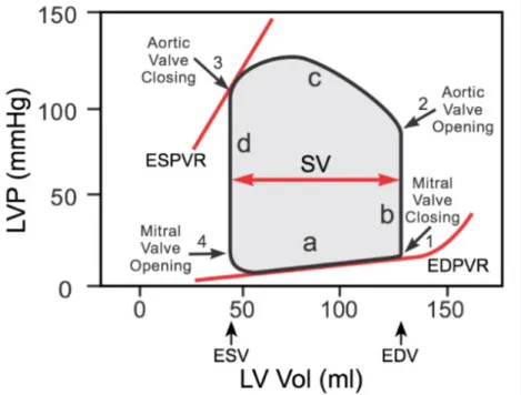
Left ventricular pressure-volume (PV) loop is derived from pressure and volume infor-mation found in the analysis of a cardiac cycle (fig.2.5). To generate a PV loop for the left ventricle, the left ventricular pressure (LVP) is plotted against left ventricular volume (LV) at multiple time points during a complete cardiac cycle(Fig. 2.6). It is used to evaluate heart muscle performances, as cardiac work and working pressures and volumes.
To illustrate the pressure-volume relationship for a single cardiac cycle, the cycle can be divided into four basic phases: ventricular filling (phase a; diastole), isovolumetric contraction (phase b; systole) , ejection (phase c; systole), and isovolumetric relaxation (phase d; diastole). Point 1 on the PV loop is the pressure and volume at the end of ventricular filling (diastole), and therefore represents the end-diastolic pressure (EDP) and end-diastolic volume (EDV) for the ventricle. As the ventricle begins to contract isovolumetrically (phase b), the mitral valve closes and the LVP increases, but the LV volume remains the same, therefore resulting in a vertical line (all valves are closed). Once LVP exceeds aortic diastolic pressure, the aortic valve opens (point 2) and ejec-tion (phase c) begins. During this phase the LV volume decreases as LVP increases to a peak value (peak systolic pressure) and then decreases as the ventricle begins to relax. When the aortic valve closes (point 3), ejection ceases and the ventricle relaxes isovolumetrically. The LVP falls but the LV volume remains unchanged, therefore the
line is vertical (all valves are closed). The LV volume at this time is the end-systolic volume (ESV), meaning that a minimum volume of blood always remains in the ven-tricle. When the LVP falls below left atrial pressure, the mitral valve opens (point 4) and the ventricle begins to fill. Initially, the LVP continues to fall as the ventricle fills because the ventricle is still relaxing. However, once the ventricle is fully relaxed, the LVP gradually increases as the LV volume increases. The width of the loop represents the difference between EDV and ESV, which is by definition the stroke volume (SV). The filling phase moves along the end-diastolic pressure-volume relationship (EDPVR), or passive filling curve for the ventricle. The slope of the EDPVR is the reciprocal of ventricular compliance. The maximal pressure that can be developed by the ventri-cle at any given left ventricular volume is defined by the end-systolic pressure-volume relationship (ESPVR), which represents the inotropic state of the ventricle.
Figure 2.6: PV loop
Variation of working conditions
The mechanical variables that influence the cardiac functions are substantially three: the prealod, the afterload and the inotropic state. They are interdependent variables that, in physiologic conditions, act simultaneously, causing PV loop changes. Figure 2.7 shows the separate effect of their variations.
Figure 2.7: How PV loop changes for: variation in preload (left), variation in the afterload (center), variation in inotropy (right)
volume if preload increases and lower stroke volume if it decreases.
Afterload It is the stress the ventricular wall is subjected to. It is related to the
resistance provided by the systemic circulation, and consequently to the mean systemic pressure. A change in afterload results in changes in systolic pressures and volumes. High afterload values results in increased systolic pressure and vice-versa.
Inotropy It is the capacity of the ventricle to generate strength. As Frank-Starling
law states (section 2.3.3), it depends on ventricular filling and the consequent streaching of its fibers. Its changes leads to changes in systolic volumes, affecting the slope of ESPVR.
2.3.3
Frank-Starling mechanism
The ability of the heart to change its force of contraction and therefore stroke volume in response to changes in venous return is called the Frank-Starling mechanism (or Starling’s Law of the heart) (fig. 2.8). The mechanism based on the fact that an increase of venous return increases the ventricular filling (end-diastolic volume) and therefore preload, that is the initial stretching of the cardiac myocytes prior to con-traction. Myocyte stretching increases the sarcomere length, which causes an increase in force generation and enables the heart to eject the additional venous return, thereby increasing stroke volume. This is intrinsic to the heart and does not depend on ex-trinsic neurohumoral mechanisms although such mechanisms can modify the inex-trinsic cardiac response.
Figure 2.8: Frank Starling curve
2.3.4
Guyton’s model
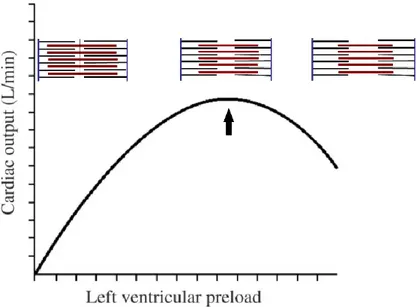
Guyton and co-workers studied the behaviour of the systemic circulation modelling it as shown in figure 2.9, left. The two parallel RC are for arterial and venous side, whit RAMP is right arterial mean pressure, CO cardiac output,Ra and Ca are arterial resistance and compliance, Rv and Cv are venous resistance and compliance.
Figure 2.9: Guyton equivalent electrical model
After a series of experiments, they were able to put in relation right atrial pressure with cardiac output and venous return (VR), as shown in figure 2.10, right, supposing to operate in steady state (therefore cardiac output equals venous return)
Cardiac output curve: it describes the state of cardiac function. As Pra increased,
the cardiac output (CO) increases. In normal physiological conditions, when Pra is 0 mmHg, CO is 5 l/min. CO starts decreasing when Pra gets close to the mean systemic pressure (MPS), corresponding to about 8 mmHg.
side. VR is 0 when Pra equals MSP, and rises when Pra decreases.
When the cardiac output and venous return function curves are plotted together on the same graph coordinates(??, right), there is a unique intersect between the two curves. This crossing point represents the steady-state operating point and it defines the cardiac output and right atrial pressure for a particular physiological condition. Whenever a change in pressures occurs, the cardiac output and the venous return curves changes, leading to a shifting in operating point, that tends in any case to come back to its equilibrium position.
Figure 2.10: Guyton cardiac output and venous return curves
2.4
Blood
The blood is a complex fluid through which oxygen and nutrients are transported all over the organism and metabolism products carried away to be eliminated. It is a connective tissue, composed by several types of cells suspended in a fluid matrix called plasma.
The cellular part includes erythrocytes and leukocyte. platelets. The red blood cells (erythrocytes) are the ones that are important for oxygenation. In fact they trans-port oxygen needed by the tissues thanks to a molecule called haemoglobin. Each haemoglobin can link till four O2 molecules, release them in tissues and carry out CO2. The total amount of erythrocytes is usually expressed with a percentage num-ber: the haematocrit. It expresses the volume of red blood cells over the volume of blood. In humans this value is between 40and 52for male and 36and 47for female.
Plasmatic part is made up mostly of water; in addition some plasmatic proteins can be
found, as well as glucose, amino acids and fatty acids. It transports also wasted prod-ucts like carbon dioxide, lactic acids and urea. Glucose and fatty acids are two main
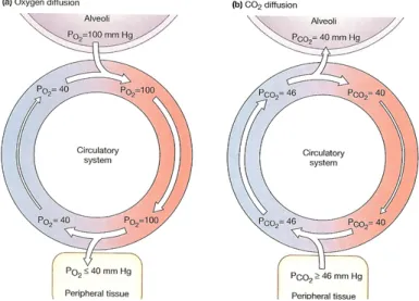
substrates used by the cardiac muscle to get energy. They are needed by myocadial cells for their aerobic metabolism which allow continuous and active contraction. The oxygenation of the blood takes place in the pulmonary circulation, where it goes into the alveoli where gas exchange occurs. The oxygen partial pressures in arterial and venous blood are shown in figure 2.11.
Chapter 3
State of the art and project
specifications
To develop an active beating heart apparatus, some general procedures need to be fol-lowed. At first, the animal heart’s source has to be determined and the organ harvested. The second step consists in biological treatments for the maintenance of the heart: it has to be provisionally stopped before connecting it to the hydraulic support system, enabling its resuscitation. This is possible thanks to cardioplegic solutions, which char-acteristics will be illustrated in details. Once connected to the hydraulic circuit, its metabolism will be restored with warm perfusion providing oxygen and nutrients to the tissues. Finally, if the functionality are correctly reactivated, the hydraulic circuit will be set to simulate the impedance of human cardiovascular system.
In the following analysis, these issues are discussed and solutions adopted by different research groups are compared.
For beating hearts tests different sizes of organs can be used, and so different animal species. Small ones are commonly employed for drug testing or studies on contrac-tile functions, coronary blood flow regulation and cardiac metabolism [5], [21]. Since the purpose of this work was the creation of a platform for human medical devices testing and surgical training, the sample needs to be as similar as possible to human myocardium in terms of anatomy and functionality. Therefore, large animal species are the most suitable; in particular the choice for this work relapsed on porcine one.
3.1
Harvesting
In order to perform an isolated active heart, the organ has to be as intact as possible, thus the surgical procedure to harvest it from the chest of the animal is important and delicate. The safer way to achieve this is to use an operatory room [20][7] [3] : indeed
the environment is sterile, physiological parameters are under control, all the devices and technologies of the OR are available for use. The drawback is the high cost and the limited availability of such a structure. Moreover ethical issues rise when animals are exploited for science.
The second option is to use slaughterhouse pigs [11][8][17][1][15]: this choice allowed to obtain the heart from animals used for food industry, avoiding ethical problems. Possible disadvantages of this choice concern biological integrity of the organ: indeed, being in a not sterile slaughterhouse setting, the organ can be contaminated. Also its physical integrity can be compromised since the butcher performs the slaughter and harvesting himself, with the risk of accidentally cut some important structures [16]. Beside these issues, the main drawback is the lose of cardiac normal functionalities after the resuscitation procedure, that can compromise the final outcome of the experiment. This risk is mostly associated to a too long warm ischaemic time, namely the time between the cardiac arrest of the animal and the cold cardioplegic perfusion. If this period exceed 7 minutes, the risk of damage progressively increases. Therefore, the explantation procedure needs to be as quick as possible to stay within limits. A further contribution to ischaemic damage, as G. George explains in his publication [8], can be the increase in creatine kinase level, due to the use of electroshock to slay the animal.
3.2
Cardioplegia
The mandatory step after the harvesting of the heart is the administration of car-dioplegic solution. It is a solution designed for routine clinical use, which aim is to arrest the heart, conserve it for some hours and protect it during the ischemic time. The contractile mechanism of the myocardium is based on the flux of Na+, K+ and Ca++ ions through the extracellular membrane. The cardioplegic solution acts on the intracellular and extracellular concentrations of these ions, preventing their flux thus stopping the contractions. In general, the heart is arrested in diastole: this means that extracellular membrane stay hyperpolarised, thanks usually to hight extracellular potassium ions concentration, that prevents the cellular ri-polarisation.
There are various recipes of cardioplegic solutions, that differ for the three aspects listed below.
1. Fluid composition: the composition of cardioplegic solutions is a mix of elec-trolytes (as K+, Ca++, Na+, Mg++, Cl-, in different amount depending on the kind of solution), pharmacological agents and energetic substrate. They are transported in the coronary circulation through crystaloid solutions or hematic ones (sometimes mixed with crystalloid).
2. Administration mode: administration can be retrograde, meaning that the car-dioplegia is infused directly in the coronary sinus, or anterograde, whether the perfusion is performed through the aorta. For some solutions, one infusion is sufficient for myocardium storage and the effects last for about 3 hours, while for others intermittent infusions every 15 - 20 minutes or even continuous ones are needed.
3. Infusion temperature: even though the use of hypothermic solutions (4°C) is convenient since low temperature reduce cellular metabolism with consequent low oxygen and glucose consumption, the administration of normothermic ones is possible as well (37°C).
Here the description of some commonly used cardioplegic solutions:
• St. Thomas: used especially in the United States, is the most spread crystalloid cold solution infused anterogradely with pressures varying between 60 mmHg and 100 mmHg. Its infusion needs to be repeated every 20 min. It takes advan-tage of the variation of K+ extracellular ions concentration to arrest the heart. For this massive presence of K+, it is very important to wash out carefully the myocardium before the resuscitation [8].
• Buckberg: it is a cardioplegic solution using blood mixed to crystalloid as per-fusate. Its administration is both anterograde and retrograde every 15-20 min, at various pressures depending on the phase, but technical and economical im-pairments limit its use.
• Custodiol: it is another kind of crystalloid cold solution, that is infused antero-gradely with a pressure of 100 mmHg till complete heart arrest. After the heart arrests, another infusion is performed at 40 - 50 mmHg after that. Its effects last about 3 hours. It has low concentration of Na++ and K+ ions, and Ca++ ions concentration equal to intracellular one.
3.3
Perfusate
After cardioplegia, heart is inserted in the developed apparatus: this is the beginning of the resuscitation phase, when cardiac functionalities need to be restored. Therefore, the organ has to be rewarmed and supplied with oxygen and nutrients. This is achieved through the circulation in the coronaries of a perfusate, a fluid that has to satisfy the following requirements:[10]:
Table 3.1: Receips of Kreb soutions[10] 1. Provide enough oxygen to support metabolism
2. Maintain transmembrane ion gradients
3. Provide energy to maintain normal contractility
Blood is the natural perfusion fluid of the myocardium, but is not the only pos-sible one. The so called Krebs-Henseleit solution represents a valid alternative. It is a transparent solution that mimics the key ionic content of blood and contains the nutrients needed to satisfy the cellular metabolism. The original composition has been adjusted through the years to satisfy the above-mentioned requirements. The table 3.1 shows some adopted compositions. Some positive aspects of using a crystalloid is the transparency, that allows to visualise internal structures like valves, and conse-quently to register videos for fluid-dynamics studies. The simplicity to obtain it and the limitless availability play a key role in its choice. Even though, two of the main drawbacks are the inadequate capacity of carrying oxygen and the low oncotic pres-sure [10]. Both Akker [1] and Araky [3] used crystalloid solutions in their tests and observed a more rapid deterioration of the myocardial performances compared to the hemoperfused hearts. This is due to a lack in oxygen content: on the counterpart, an augmented coronary flux acted as a feedback to try to overcome this limitation. One answer to this problem is the addition of red blood cells to the perfusate: this increases the oxygen transport capacity, but loss of transparency and complexity of the proce-dure makes this solution not widely used [5]. On the other hand, the employment of the blood is very efficient on the oxygenation side, but lacks in availability: indeed, the collection from slaughter animals is not that straightforward. Before the use, the blood needs to be conveniently treated. Addition of heparin in a proportion of 5000 U/l is the first essential factor, otherwise the blood coagulates and become unusable. pH has to
by many factor as CO2 levels and temperature. For this reason it is important to make the blood pass through the oxygenator and heat exchange modules before adjust the pH, if needed. Moreover, enrichment of blood with glucose (or dextrose) and piruvate is useful to provide energy to the myocardium: the first is one of the main substrate used by heart muscle in the production of ATP, while the second is a free fatty acid, exploited as well for energy production. Some authors suggest also the use of drugs to help the resuscitation procedure: substances like lidocaine can help to restore normal cardiac contraction in case of ventricular fibrillation. To prevent infections in some cases antibiotics are added, but this is in the prospective of long lasting experiments.
3.4
Langendorff reperfusion
As mentioned above, after the administration of cardioplegic solution and housing of the heart in the apparatus, it needs to be reactivated.
The technique used to resuscitate the heart is called Langendorff reperfusion, from the name of its author. It is a procedure based on inducing retrograde blood (or Krebs solution) flow into the coronary circulation through a cannula inserted into the aorta. In this way the aortic valve closes because of the back pressure gradient and the coronaries are perfused via the ostia of the aortic root. After passing through the coronaries the perfusate is drained into the right atrium via the coronary sinus. In the original work, Langendorff carried on the perfusion with Krebs-Henseleit solution with a constant pressure, but also a constant flow can be used as a driving parameter. The constant
pressure modality can be given by gravity of a column of fluid or by opportunely
setting the pump used for perfusion. In the constant flow modality, a flow meter is employed and the flow is kept at constant level. (Fig.3.1) A constant flow preparation provides usually more reproducible results, but some autoregulatory mechanisms may be partially lost with respect to a constant pressure preparation. For example, the myocardium won’t be able to adjust flow rate in response to an increase in workload, potentially leading to ischemia. The authors that used a constant pressure modality set it between 60 mmHg and 70 mmHg [20][15][7]; some others decided to switch from constant flow to constant pressure after some minute of reperfusion [5][8][17]. In general, the hearts recover spontaneous contractility after 15 – 30 min of Langendorff reperfusion [10] [7][11]. If this event doesn’t occur, defibrillation with a power from 10 J to 40 J [11][16] is used to restore sinus rhythm. This manoeuvre is also employed if the contractions are not synchronised. Sometimes a pacemaker is attached to the heart to help maintaining frequency within physiological range.
Figure 3.1: On the right: Langendorff circuit controlled in flow. On the left: Lagendorff circuit controlled in pressure [22]
3.5
Hydraulic circuit components
3.5.1
Afterload
Considering systemic circulation, the afterload is the load against which the heart con-tracts to eject blood, namely the impedance given by body districts. To simulate this working condition in the hydraulic system, the afterload is manufactured to provide a suitable impairments to the flow which permits to obtain pressure waves as similar as possible to the physiological ones. In the analysed literature, a variety of solutions were used to simulate the impedance of human cardiovascular system. The easiest is to use a simple column of fluid that, depending on the high, imposes a certain pressure and consequently a resistance to the flow. [3][15]. D. Rosenstrauch[20] used a reservoir with a compliance chamber in series: the aim was to correct the cyclic fluctuations developed by the pumping action of the ventricle (2-elements Windkessel model). A more complex module has been achieved by J. De Hart [11], who designed it as a 3-elements Windkessel model using two resistances and a polyurethane flexible tube as compliance. In this kind of approach the dimensioning of the compliance is difficult and obtaining the required properties during manufacturing proccess can be hardly achievable. Mattew A. Schechter and co-workers [21] used in their mock loop a centrifugal pump pumping against the heart: as the author explains, this choice was versatile since adjusting the pump settings it can be use for different animal species at different regimes. Another solution, adopted by Geven MC and collegues, is to merely use two clamps to partially occlude the line downward the aorta.
R.Vismara and co-workers[24] designed an impedance simulator based on a lumped parameters model of three elements: a characteristic resistance Rc, a peripheral re-sistance Rp and a compliance chamber C (Fig.3.2). The choice of a RCR model is
supported by studies that confirm it as the best compromise between accuracy in the reproduction of pressure curves and complexity in the fabrication. Both the resistance modules were realised with an hollow cylinder filled with a polymeric net rolled up around a bar, simulating the structure of a porous material through which the fluid passes. Moreover, the peripheral resistance was adjustable: a bar can be inserted in and out the polymeric net, determining a longer or shorter path for the fluid to pass through the net. This peculiarity makes the device versatile for the simulation of a wide range of working condition, from hypertension to hypo-tension, and of hypothet-ical adult or paediatric patients. Nevertheless it has been used in ForcardioLab for many test on passive beating heart setup providing good working conditions, two main issues arises when it is considered for the use in active beating heart apparatus: the non-compatibility with a particulate fluid and the difficulties in reproducibility. The use of a net to create the resistances can rise problems when a particulate fluid as blood passes through it: in fact particles can coagulate preventing the normal stream, increasing progressively the resistance and leading finally to an abnormal change in working condition. Also the cleaning of the nets would become a problem when blood is used instead of water. Moreover the way in which the net was rolled up to obtain the predicted values of resistances is hardly repeatable.
Figure 3.2: Afterload realised by R.Vismara et al.[24]
3.5.2
Oxygenator and heat exchanger
This component is the one normally used in extra-corporeal circulation, integrating both the blood oxygenation and warming functions. Since the heart muscle has to be nourished, the circulating blood should continuously be purified from wasted gas
(CO2) and enriched by oxygen. The temperature has to be kept at constant body value to mimic in vivo conditions. This component exactly satisfy these demands. The oxygenator provide gasses exchanges: the most modern type of oxygenator is the membrane one. Blood and gas mixture flows are separated by a polymeric membrane. Through this membrane, gas exchange takes place by concentration gradient. The function of the heat exchanger is to warm up the blood. Water is heated in a separate compartment and it is recirculate in the oxygenator, separated from blood by polymeric or metallic walls: in this way, the blood is warmed up by conduction.
3.5.3
Preload
This element provides fluid for the atrium and hence controls its filling pressure in a passive way. It is usually realized with an open-air reservoir that provide a certain pressure depending on the fluid level. [7][3][15]. J. De Hart in his work [11]introduce a slightly different kind of preload, that controls atrial filling by means of a Starling resistance (Fig:3.3). This consists of a collapsible tube closed within an air chamber: by changing the static air pressure, the collapse grade of the tube is controlled, resulting in a change in resistance and therefore in atrial filling.
Figure 3.3: Starling resistor
3.5.4
Arterial filter
Thanks to a porous membrane with pore diameter between 200 µm and 400 µm , this device stops components bigger than the pore size as clots or bubbles. It is useful to avoid these elements to enter in the coronary circulation, where they can provoke
embolism or occlusion and consequent infarction due to the vessel’s very small diameter. D. Modersohon [15]introduced also a leukocytes filter and a dialysis circuit. The first is used to avoid heart damage by activated leukocytes, while the second provide a long lasting test thanks to the supply of glucose and the removal of wasted product that otherwise would remain in the circulating blood.
Figure 3.4: PhysioHeart platform [11]
3.6
Working mode
After the Langendorff reperfusion, once the heart has recovered its sinus rhythm, pas-sage to working mode is possible. There are three different configurations in which the heart can work:
1. Langendorff configuration: this is exactly the same configuration used for resusci-tation procedure. The coronaries perfusion is performed through the cannulated aorta and the heart contracts without ejection. It is usually enough for assessment of functional capacities as contractile strength and ventricular pressure[8][1][17]. 2. 2-chambers working mode: in this configuration the left heart is only connected to the hydraulic circuit representing circulatory system impendance, and hence the perfusate is forced to pass through it. An example of a 2-chambers working left heart circuit is the PhysioHeart platform (Fig.3.4) described in the publica-tion of J. De Hart[11]. The blood was pumped by a centrifugal pump (CP2) from a venous reservoir (VR2) through an heat exchanger (HE) and an arterial blood filter (BF) to a custom made preload (PL) and connected to the left atrium. The left ventricle ejected then into a custom-made afterload (AL) and returned into the reservoir (blu line).The pathway was essentially the same for the D.
Rosen-strauch’s[20], Y. Araki’s[3] and D. Modersohon’s[15] mock loops, performing a 2-chambers beating heart as well.
3. 4-chambers working mode: in this configuration the whole organ is involved, so both the ventricles contract and eject through the circuit. Two separate circuits are developed in this case, one simulating the systemic circulation and the other simulating the pulmonary circulation. An example of this working mode is the one realised by E. Chinchoy [7](Fig.3.5). Here the two atria were supplied by passive-filling using open-to-air chambers. Then, Krebs perfusate was ejected from the left ventricle to the aorta and from the right ventricle to pulmonary artery. Fluid from both the aorta and the pulmonary artery was collected into an open drain, then it passed to a reservoir, an oxygenator and was pumped back into the two open-to-air chambers to restore preload levels.
Since nutrients and oxygen that permit heart muscle contraction are carried by coronaries, the flux in these vessels is important. Dealing with their perfusion, there are two solutions presented in the litterature that can be used together with 2 or 4 chambers configurations previously described. One option considered natural
perfu-sion to be maintained, meaning that coronaries are perfused by aortic stream as in
physiological conditions [20][7][3]. The other possibility was to build up a secondary circuit just for coronary circulation (selective perfusion): in this case the coronaries were cannulated and connected to the circuit. This allows to use blood just for coro-nary circulation, employing transparent fluid instead inside the ventricles in order to have video recording or images. In this configuration coronary perfusion parameters as flow and pressure are arbitrary controlled, resulting in difficulties in reproducing the exact physiological conditions. Also feedback mechanism are totally prevented due to external control.
For example in PhysioHeart[11], the platform previously described (Fig.3.4), an addi-tional loop for selective perfusion was build up (red line). The blood was pumped from a venous reservoir (VR1) by a centrifugal pump (CP1) to an arterial blood filter and to an oxygenator combined with an heat exchanger. Subsequently the flow was directed into the cannulated coronary and returned to the right atrium, through the tricuspid valve, to the right ventricle. From there, blood returned into the venous reservoir.
3.7
Obtained results
The analysis of the state of the art gave a large prospective on methods and requiments to keep the heart sample beating. The variety of solutions described by


![Table 3.1: Receips of Kreb soutions[10]](https://thumb-eu.123doks.com/thumbv2/123dokorg/7505387.104806/39.892.136.775.128.360/table-receips-of-kreb-soutions.webp)
