www.advmat.de
Anatomy of Skyrmionic Textures in Magnetic Multilayers
Wenjing Li, Iuliia Bykova, Shilei Zhang, Guoqiang Yu,* Riccardo Tomasello,
Mario Carpentieri, Yizhou Liu, Yao Guang, Joachim Gräfe, Markus Weigand,
David M. Burn, Gerrit van der Laan, Thorsten Hesjedal, Zhengren Yan, Jiafeng Feng,
Caihua Wan, Jinwu Wei, Xiao Wang, Xiaomin Zhang, Hongjun Xu, Chenyang Guo,
Hongxiang Wei, Giovanni Finocchio,* Xiufeng Han, and Gisela Schütz
DOI: 10.1002/adma.201807683
Magnetic skyrmions are topological magnetic structures with quasiparticle properties, which have received consid-erable attentions recently due to their striking properties, in large parts, as they have a small size and can be manipu-lated with ultralow electrical current densities.[1–9] Skyrmions stabilized by Dzyaloshinskii–Moriya interaction (DMI) have been observed in noncentrosym-metric bulk materials,[10–14] as well as in heavy metal/ferromagnetic metal heterostructures.[15–29] Especially skyr-mions in engineered multilayers have the potential for practical applications due to their high operating temperature and materials compatibility with standard semiconductor processes.[3,4]
In previous studies, the skyrmion texture in a multilayer was assumed to be identical for all the individual mag-netic layers, and thus the skyrmion was effectively described as a 2D spin texture using renormalized parameters.[21–23,27,29]
Room temperature magnetic skyrmions in magnetic multilayers are considered
as information carriers for future spintronic applications. Currently, a detailed
understanding of the skyrmion stabilization mechanisms is still lacking in these
systems. To gain more insight, it is first and foremost essential to determine
the full real-space spin configuration. Here, two advanced X-ray techniques are
applied, based on magnetic circular dichroism, to investigate the spin textures
of skyrmions in [Ta/CoFeB/MgO]
nmultilayers. First, by using ptychography,
a high-resolution diffraction imaging technique, the 2D out-of-plane spin
profile of skyrmions with a spatial resolution of 10 nm is determined. Second,
by performing circular dichroism in resonant elastic X-ray scattering, it is
demonstrated that the chirality of the magnetic structure undergoes a
depth-dependent evolution. This suggests that the skyrmion structure is a complex
3D structure rather than an identical planar texture throughout the layer stack.
The analyses of the spin textures confirm the theoretical predictions that the
dipole–dipole interactions together with the external magnetic field play an
important role in stabilizing sub-100 nm diameter skyrmions and the hybrid
structure of the skyrmion domain wall. This combined X-ray-based approach
opens the door for in-depth studies of magnetic skyrmion systems, which
allows for precise engineering of optimized skyrmion heterostructures.
Spin Textures
Dr. W. Li, Prof. G. Yu, Dr. Y. Liu, Y. Guang, Z. Yan, Prof. J. Feng, Prof. C. Wan, Dr. J. Wei, X. Wang, X. Zhang, Dr. H. Xu, C. Guo, Prof. H. Wei, Prof. X. Han Beijing National Laboratory for Condensed Matter Physics
Institute of Physics
Chinese Academy of Sciences Beijing 100190, China E-mail: [email protected]
Dr. W. Li, Prof. G. Yu, Dr. Y. Liu, Y. Guang, Z. Yan, Prof. J. Feng, Prof. C. Wan, Dr. J. Wei, X. Wang, X. Zhang, Dr. H. Xu, C. Guo, Prof. H. Wei, Prof. X. Han Center of Materials Science and Optoelectronics Engineering
University of Chinese Academy of Sciences Beijing 100049, China
Dr. W. Li, Prof. G. Yu, Dr. Y. Liu, Y. Guang, Z. Yan, Prof. J. Feng, Prof. C. Wan, Dr. J. Wei, X. Wang, X. Zhang, Dr. H. Xu, C. Guo, Prof. H. Wei, Prof. X. Han
Songshan Lake Materials Laboratory Dongguan, Guangdong 523808, China
Dr. I. Bykova, Dr. J. Gräfe, Dr. M. Weigand, Prof. G. Schütz Max Planck Institute for Intelligent Systems
Heisenbergstraße 3, 70569 Stuttgart, Germany
The ORCID identification number(s) for the author(s) of this article can be found under https://doi.org/10.1002/adma.201807683.
Prof. S. Zhang, Prof. T. Hesjedal Department of Physics Clarendon Laboratory University of Oxford
Parks Road, Oxford OX1 3PU, UK Dr. R. Tomasello
Institute of Applied and Computational Mathematics FORTH
GR-70013 Heraklion-Crete, Greece Prof. M. Carpentieri
Department of Electrical and Information Engineering Polytechnic University of Bari
Bari 70125, Italy
Dr. D. M. Burn, Prof. G. van der Laan Magnetic Spectroscopy Group Diamond Light Source Didcot OX11 0DE, UK Prof. G. Finocchio
Department of Mathematical and Computer Sciences Physical Sciences and Earth Sciences
University of Messina Messina 98166, Italy E-mail: [email protected]
www.advmat.de www.advancedsciencenews.com
However, the multilayer typically shows a more complicated domain wall texture.[30–34] Recent theoretical and experimental studies have given strong hints that the skyrmion profiles in multilayers are in fact a function of layer position in the stack, complicating the understanding of these systems.[35–37] It is anticipated that in multilayers the dipole–dipole interactions give rise to the stabilization of hybrid skyrmions, i.e., skyr-mions characterized by a thickness-dependent reorientation of their domain wall chirality. Thus, to completely understand the skyrmion texture and the corresponding stabilization mecha-nism, it is important to precisely probe the skyrmion texture in both 2D (within the film plane) and 3D (perpendicular to the film plane).
Here, utilizing a high-resolution ptychographic imaging technique, we map the 2D spin texture of skyrmions in a Ta/[CoFeB/MgO/Ta]16 multilayer. Taking advantage of the improved spatial resolution for ptychography of 10 nm,[38–40] the out-of-plane spin profile of skyrmions can be accurately probed. Furthermore, using circular dichroism in resonant elastic X-ray scattering (CD-REXS) we can explore the depth-dependent chirality of the skyrmion texture. We were able to determine the chirality of the hybrid domain wall[36] directly in 3D, confirming the depth dependence of the chiral spin tex-tures of hybrid skyrmions. Combining both the ptychography and CD-REXS results allowed us to capture the 3D texture of skyrmions, providing adequate information to develop a full understanding of the underlying stabilization mechanism of small skyrmions in magnetic multilayers.
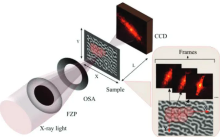
The magnetic heterostructure studied in this work consists of Ta/[CoFeB/MgO/Ta]16. First, we demonstrate high-resolution images of stable skyrmion phase in these samples using X-ray ptychography. The resolution of conventional X-ray micro-scopes is limited by the focusing element, e.g., Fresnel zone plates (FZP), and remains in the range of 20–25 nm. There-fore, for the study of sub-100 nm-sized magnetic skyrmions, we employed X-ray ptychography, which is a higher resolving power coherent scattering imaging technique. Resonant X-ray ptychography for imaging magnetic domains using circular polarized hard[38] and soft[39] X-rays showed significant improve-ment in its resolution and can potentially provide a wavelength-limited resolution of few nm[40] over extended sample areas. The ptychography measurements in this work were performed on the MAXYMUS beamline UE46 at BESSY II synchrotron (Berlin, Germany). Figure 1 shows the basic geometry of a ptychographic set-up. The reconstructions of phase and ampli-tude images were performed using SHARP ptychography package.[41]
Figure 2b–d depict the evolution of magnetic domain pat-terns with external magnetic field, as captured by ptychography for the sample with a CoFeB layer thickness of tCoFeB = 1.45 nm. The film exhibits a labyrinthine pattern at zero field, after saturation at an out-of-plane magnetic field of 240 mT. At higher fields, the labyrinthine pattern breaks down into a stripe domain pattern, which further transforms into a skyr-mion pattern. After the magnetic field reaches a critical value (≈150 mT), a stable skyrmion phase is formed.
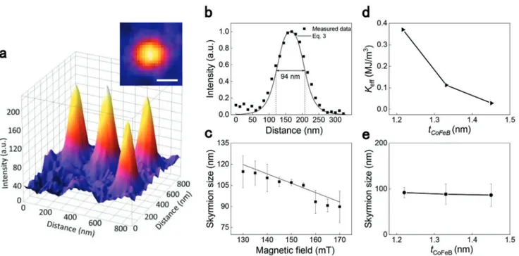
The out-of-plane spin profile of the skyrmions in the sample with tCoFeB = 1.45 nm is presented in Figure 3a. These skyr-mions appear isolated and exhibit smooth edges (see inset in Figure 3a). Figure 3b shows a comparison between a typical measured profile (squares) and the calculated profile using Equation (3) (solid line) (the ansatz was already proposed in previous work;[42] see Experimental Section). In particular, we plot the z-component of the magnetization, which has been normalized to go between 0 and 1. The agreement between the experimental and calculated results is excellent.
Next, the skyrmion size is determined as a full width of half-maximum and the smallest skyrmion size found for
tCoFeB= 1.45 nm is (87 ± 3) nm. The out-of-plane spin profile also indicates that the skyrmion has a compact structure, i.e., that the z-component of the spin continuously varies its ampli-tude without exhibiting a plateau (characteristic for a magnetic Figure 1. Sketch of the ptychographic imaging setup. The sample is
raster-scanned while the focused X-ray beam remains fixed. The focusing of the beam is achieved by a Fresnel zone plate (FZP), where an order sorting aperture (OSA) blocks the nondiffracted zero-order light. A diffraction image is recorded in the far-field by a CCD camera (at distance L) for every scanning position. Applying an iterative phase retrieval algorithm allows for the reconstruction of the phase and amplitude images.
Figure 2. a) Schematic of the CoFeB multilayer stack. b–d) Ptychography images taken in different out-of-plane magnetic fields. The bright and dark
bubble) at the core of the magnetic texture. This observation is expected as the skyrmion size is about twice the domain wall width (of 40–42 nm as obtained from the ptychography meas-urement). It is noted that the domain-wall width measured by ptychography also corresponds well to the calculated value (∆DW=π A K/ eff ≈41 nm, where A and Keff are the exchange stiffness and effective anisotropy, respectively, see Note S1 in the Supporting Information).
Figure 3c shows the skyrmion size as a function of applied external field. The skyrmion size decreases from 115 to 87 nm as the field increases. The skyrmion diameter is one order of magnitude smaller than that of the Ta/CoFeB/MgO/Ta multi-layer (≈1.3 µm) (see Figure S2 in the Supporting Information), and it is comparable to that of Pt-based multilayer with large DMI.[21,22] Typically, the amplitude of the DMI is considered to be an important factor for the stabilization of small skyrmions. However, the DMI originated from the Ta/CoFeB interface (< 0.5 mJ m−2) is much smaller than that in the Pt-based mul-tilayers (≈2 mJ m−2).[43,44] The DMI value of our multilayer can be expected to be of the same order of that in single layer since it is mainly determined by the Ta/CoFeB interface (assuming a homogeneous interfacial quality). Therefore, the significantly reduced skyrmion size cannot simply be ascribed to a relatively large DMI.
However, beyond the DMI, there are other interactions that can lead to a reduction of the skyrmion size, namely, the effective perpendicular magnetic anisotropy, the long-range dipole–dipole interaction, and the Zeeman interaction. First, we studied the dependence of the skyrmions size on the CoFeB layer thicknesses to explore the role of the effective perpendicular magnetic anisotropy, as shown in Figure 3d,e.
Although the effective anisotropies are quite different, only a minor tuning of the external field was required to stabilize skyrmions of essentially the same size, thereby ruling out that anisotropy plays a major role in the significant decrease of the skyrmion size. However, the variation of the anisotropy results in the change of skyrmion density, which was also reported in the previous work.[22] On the other hand, the external mag-netic field allows for a tuning of the skyrmion size from 80 to 120 nm (tCoFeB = 1.45 nm), as shown in Figure 3c, indicating its importance for skyrmion size. To further investigate the effect of dipole–dipole interactions, micromagnetic simulations were performed as a function of layer repeats, while maintaining all the other parameters the same (as an example see Figure S3 in the Supporting Information). The simulation results show that the skyrmion size even increases as a function of the number of layers. In summary, our study suggests that a combination of dipole–dipole interactions and the external field plays the key role in determining the small size of skyrmion in the studied multilayer.
Next, we reveal the 3D spin orientation of the system by CD-REXS.[45–47] It has been demonstrated that the CD extinc-tion effect in the reflecextinc-tion REXS geometry is sensitive to the twisting angle of the spin spirals and skyrmions.[45] Depending on the magnetic ordering type, the magnetic scattering pat-tern either exhibits peaks (magnetic motifs have a well-defined modulation wavevector) or a diffuse ring pattern (spatially cor-related motifs not long-range ordered). Figure 4b,c shows simu-lated CD-REXS patterns for (unordered) Néel-type spin spiral modulations with opposite chirality. A so-called extinction vector can be defined, which separates the positive and negative parts of the dichroic pattern, and which is directed opposite for Figure 3. a) Surface plot of the skyrmion structure for a tCoFeB = 1.45 nm sample in an out-of-plane field of −165 mT. The inset shows the image of a skyrmion for an out-of-plane magnetic field of −155 mT. The scale bar corresponds to 100 nm. b) Variation of the intensity for a single skyrmion with distance (experimental data, black squares) together with the analytical skyrmion profile obtained from Equation (3) (solid line). c) Dependence of the skyrmion size on the magnetic field. d) Dependence of the effective anisotropy Keff, and e) measured skyrmion size on the CoFeB thickness. The skyrmion sizes are determined based on the ptychographic images acquired at −105, −110, and −130 mT for tCoFeB = 1.22, 1.33, and 1.45 nm, respectively.
www.advmat.de www.advancedsciencenews.com
the two examples shown in Figure 4b,c. The azimuthal angle of the extinction vector has a one-to-one correspondence to the twisting angle of the spin spirals or the skyrmions.[45] For example, in Figure 4b,c, the pure Néel-type spiral/skyrmion leads to a horizontal extinction vector. For comparison, a pure Bloch-type spiral/skyrmion would lead to a vertical extinction vector. On the other hand, if the handedness of the Néel-type motif reverses, the extinction vector remains horizontal; how-ever, the extinction vector reverses direction, i.e., the positive and negative dichroism regions change positions (compare Figures 4b and 4c). This experimental principle has recently been applied to [Ir/Co/Pt]n multilayered systems,[36,48] showing its robust and general applicability. Moreover, by changing the probing depth in the same type of experiment, depth-dependent information can be extracted.
We performed CD-REXS on the multilayer with
tCoFeB = 1.45 nm to investigate the depth-dependent evolution of the modulated domain-wall twisting angles, i.e., the devia-tion from the standard Néel-type domain walls, which are influ-enced by the DMI. The REXS experiments were carried out in the RASOR diffractometer on beamline I10 at the Diamond Light Source (UK) with the sample in the stripe-domain phase at room temperature and zero magnetic field. Figure 4a shows the scattering geometry with incident X-rays of wavevector
ki and varying incident angle αi at a photon energy of 707 eV (i.e., Fe L3 edge), and the scattered beam with ks. The CD-REXS pattern is obtained from the difference between the scattering intensities for left- and right-circularly polarized X-rays. The dichroism extinction condition directly reveals the twisting
angle of the magnetic structure averaged over the probed depth. More importantly, by varying αi, different probing depths can be achieved, suggesting a powerful method that can selectively measure the magnetic structure from the surface or the average over a given depth in the bulk.
The main CD-REXS results are shown in Figure 4d,e. At lower angles (αi = 10°), in principle two magnetic peaks are observed, corresponding to the Friedel pair coming from the spiral modulations. Nevertheless, the two peaks are smeared out into rings due to the diffuse scattering. One can clearly distinguish the blue and red regions representing the oppo-site dichroism. The extinction vector is found to be hori-zontal and pointing to the right, indicating a right-handed Néel-type spiral modulation on the top surface. By increasing the probing depth, i.e., αi is increased to 40°, soft X-rays can transmit through the entire multilayer (i.e., 86 nm). Now, the motif’s chirality is reversed. It is worth emphasizing that in the case of the bulk-sensitive probing shown in Figure 4e, although X-rays transmit through the entire thickness of the multilayer, the CD from the bottom layers contributes less than from the top layers. In a simple approximation, the intensity exponentially decays as the X-rays propagate deeper into the multilayer. Therefore, if the system undergoes a sym-metric Néel–Bloch–Néel transformation in depth, and a pure Bloch layer occurs in the very center of the film, a chirality-reversal phenomenon would not expected to be observable. In other words, the symmetrically flipped chiral layers from the bottom region of the film do not contribute sufficiently to the CD signal to dominate the overall scattering signal, which Figure 4. Depth-dependent evolution of the domain wall-twisting angle determined by CD-REXS in reflection geometry. a) Illustration of the
3D profile of the spin spiral state in the multilayer structure. Both top and bottom surfaces have Néel-type spin spiral modulations, but with opposite chirality. The system undergoes a gradual transition in depth from Néel to Bloch, and back to Néel-type spirals. b,c) Simulated CD-REXS patterns in a single-layer model for (b) a pure Néel-type structure with right-handed chirality and (c) a pure Néel-type structure with left-handed chirality. d,e) Experimental data are showing the CD-REXS pattern for different incident angles corresponding to (d) surface- and (e) bulk-sensitive probing.
averages over all layers. The only scenario in which such a chi-rality reversal can be observed in CD-REXS is when the Bloch-type intermediate layer is located closer to the surface, as is illustrated in Figure 4a.
From the spiral structural twisting evolution along the thickness, assisted by micromagnetic simulations, one can conclude that in the multilayer with 16 repeats, the interfacial DMI takes a moderate value between 0.3 and 0.5 mJ m−2. The competition between the dipole–dipole interaction and DMI lifts the Bloch-type layer toward the top surface. In this near-surface region, the right-handed Néel spirals quickly transform into Bloch-type spirals. On the other hand, toward the bottom of the film, the transition back to the now left-handed Néel spiral is more gradual. Our depth-dependent CD-REXS meas-urement directly confirms the existence of hybrid spin spiral structures.
The experimentally observed structure is also well repro-duced by micromagnetic simulations. In particular, we performed simulations of a multilayer with 16 ferromagnetic layer repeats. Figure 5a,b show the cross-section of the micro-magnetic ground state (D = 0.4 mJ m−2 and out-of-plane applied field of 150 mT) and the relative skyrmion domain wall angle (see inset in Figure 5b), respectively. A hybrid skyrmion is sta-bilized in the multilayer, where the bottom (top) ferromagnetic layer hosts a Néel skyrmion with radially outward (inward) pointing spins (Figure 5c,e), while the position of the Bloch
skyrmion (Figure 5d) depends on the value of the DMI. In par-ticular, at zero DMI, the dipole–dipole interaction promotes the formation of a Bloch-type skyrmion right in the middle layer (not shown). However, the presence of DMI leads the Bloch-type skyrmion to move to the 10th ferromagnetic layer. These results are in excellent agreement with the experimental data (compare Figures 4 and 5).
To summarize, we have performed soft X-ray magnetic ptychography to precisely capture the out-of-plane spin profile of sub-100 nm-sized skyrmions in a multilayer film, which exhibits a complex spin configuration. The experimental results indicate that the combined effect of dipole–dipole interaction and applied magnetic field are responsible for the significant shrinking of the skyrmion size in these mag-netic multilayers. Therefore, we can draw the conclusion that DMI is not the only crucial factor that determines the size of skyrmion in magnetic multilayers. Furthermore, CD-REXS experiments were carried out to study the depth dependence of the chirality of the domain walls, directly revealing that the top and bottom layers have opposite chirality. Our results, achieved by combining advanced X-ray methods, provide important insight into the formation and characteristics of skyrmions in magnetic multilayers. These findings are of vital importance for further engineering heterostructures for appli-cations in future magnetic skyrmion storage and information technologies.
Figure 5. Micromagnetic simulation results. a) Cross-sectional view of the 16-repeat multilayer sample. b) Illustration of the transition from a Néel
skyrmion with spins pointing radially inward toward the center (at the top of the stack) to the opposite orientation, i.e., outward-pointing radial spins, at the bottom of the stack. The angle plotted in b) represents the respective rotation of the spins in the transition region (white ring in c–d)), where 0° corresponds to all spins being tangential (and counter-clockwise). c–e) Spatial distribution of the magnetization for different layers (top, middle, bottom), where the color represents the z-component of the magnetization mz (red positive and blue negative) while the arrows represent the magnetization direction in (a) and its in-plane component in (c–e).
www.advmat.de www.advancedsciencenews.com
Experimental Section
Imaging Experiments: The microscopy images were acquired on the scanning transmission X-ray microscope MAXYMUS at the synchrotron BESSY II (Helmholtz-Zentrum Berlin, Germany). The multilayer skyrmion samples were illuminated using a zone plate, giving a 120 nm focal spot, which was raster-scanned with a spot overlap of ≈60%. A CCD camera was placed 8 cm downstream of the sample, resulting in a ≈11 nm output pixel size with the energy tuned to the Fe L3 absorption edge (708.4 eV). Each scanning point was exposed for 200 ms to ensure sufficient dynamic range. For ptychographic imaging, low-resolution Fresnel zone plates (FZP) were used to produce a larger focal spot with coherent and uniform illumination at the sample plane, which required fewer diffraction patterns per area and thus enabled short scanning times. The magnetic properties were measured by a superconducting quantum interference device (SQUID).
Sample Preparation: The Ta(5 nm)/[CoFeB(t nm)/MgO(2 nm)/ Ta(3 nm)]16 samples were grown on silicon nitride membranes, and a semi-insulating Si substrate with 100 nm thick thermally formed SiO2 layer by magnetron sputtering. The thickness of the CoFeB layer was continuously varied by growing a wedge shape to tune the perpendicular magnetic anisotropy. The vacuum pressure was <3 × 10⁻⁶ Pa. The deposition rates for Ta, CoFeB, and MgO were 0.48, 0.30, and 0.05 Å s−1, respectively, using a power of 100 W and a deposition pressure of 0.3 Pa.
Micromagnetic Simulations: The micromagnetic simulations were performed by means of a state-of-the-art micromagnetic solver that numerically integrates the Landau–Lifshitz–Gilbert equation by applying the Adams–Bashforth time solver scheme[42,49]
eff d d d d m m h m m τ = −
(
×)
+α × τ (1)where m = M/Ms is the normalized magnetization of the ferromagnet, and τ = γ0Mst is the dimensionless time, with γ0 being the gyromagnetic ratio, and Ms the saturation magnetization. heff is the normalized effective field, which includes the exchange, interfacial DMI, magnetostatic, perpendicular anisotropy, and external fields. α is the Gilbert damping. The interfacial DMI contribution hDMI is obtained from the functional derivative of the DMI energy density εDMI = D[mz∇·m−(m·∇)mz] assuming a thin film
( )
∂∂ = 0mz andm m hDMI 2 [( )ˆ ] 0 S z D M z m µ
= − ∇ ⋅ − ∇ .[8,50] D is a parameter taking into account the intensity of the DMI, mz is the out-of-plane component of the
normalized magnetization, µ0 is the vacuum permeability, and zˆ is the unit vector along the out-of-plane direction. The interfacial
DMI boundary conditions are also considered dm 2 (ˆ n) m
dn D
Az
= × × ,
where n is the unit vector normal to the edge, and A is the exchange constant. We used a discretization cell of 3 × 3 × 1.45 nm3, and the following physical parameters: MS = 1.18 MA m−1, exchange constant A = 10 pJ m−1, perpendicular anisotropy constant K
u= 0.90 MJ m−3, and out-of-plane external field Hext= 150 mT.
Analytical Skyrmion Profile: The polar angle Θ0(r), which describes the skyrmion profile, is obtained from the following equilibrium equation
r
d
r h
1 sin cos sin sin
2
0
( )
ξ2 2 0 0 2 0 0∇ Θ = + Θ Θ − Θ + Θ (2)
which is calculated from the minimization of the energy functional.[42] In Equation (2), ξ2= − =1 2 /µ −1
u 0 s2
Q K M , h = Hext/Ms, r = ρ/lex is the reduced polar coordinate, and d = |D|lex/A, where lex= 2 /Aµ0Ms2 is the exchange length. An approximated solution of Equation (2) can be found by using the following ansatz[42]
r r r e r r
tanΘ02
( )
= sk ξ(sk−) (3)where rsk = Rsk/lex is the reduced equilibrium skyrmion radius, defined as mz(rsk) = 0, corresponding to the energy minimum. For our parameters, ξ = 0.169 and Rsk= 47.05 nm.
Supporting Information
Supporting Information is available from the Wiley Online Library or from the author.
Acknowledgements
W.L., I.B., and S.L.Z. have contributed equally to this work. Financial support from the National Natural Science Foundation of China (NSFC Grant No. 11874409), the NSFC-Science Foundation Ireland (SFI) Partnership Programme (Grant No. 51861135104), and the 1000 Youth Talents Program is acknowledged. This project was also supported by the National Key Research and Development Program of China (Grant No. 2017YFA0206200), and the NSFC (Grant Nos. 11434014, 51620105004, 11674373, and 11804380), as well as the Strategic Priority Research Program (B) (Grant No. XDB07030200), the Key Research Program of Frontier Sciences (Grant No. QYZDJ-SSW-SLH016), and the International Partnership Program (No.112111KYSB20170090) of the Chinese Academy of Sciences (CAS). The authors acknowledge Diamond Light Source for beamtime on beamline I10 under proposal SI-18898. The authors thank the Helmholtz-Zentrum Berlin for beamtime at the MAXYMUS endstation at BESSY2. G.F. and R.T also acknowledge the project “ThunderSKY,” funded by the Hellenic Foundation for Research and Innovation (HFRI) and the General Secretariat for Research and Technology (GSRT), under grant agreement No. 871, and the executive programme of scientific and technological cooperation between Italy and China for the years 2016–2018 funded by Ministero degli Affari Esteri e della Cooperazione Internazionale (CN16GR09) and Ministry of Science and Technology (2016YFE0104100). S.L.Z. and T.H. thank the Engineering and Physical Sciences Research Council (UK) under grant P/N032128/1. Y.L. acknowledges support from the Institute of Physics, Chinese Academy of Sciences through the International Young Scientist Fellowship (Grant No. 2018001). G.Y. acknowledges helpful discussions with Prof. Haifeng Du.
Conflict of Interest
The authors declare no conflict of interest.
Keywords
resonant elastic X-ray scattering, skyrmion, spin texture, X-ray ptychography imaging
Received: November 28, 2018 Revised: January 28, 2019 Published online:
[1] N. Nagaosa, Y. Tokura, Nat. Nanotechnol. 2013, 8, 899. [2] A. Fert, V. Cros, J. Sampaio, Nat. Nanotechnol. 2013, 8, 152. [3] A. Fert, N. Reyren, V. Cros, Nat. Rev. Mater. 2017, 2, 17031. [4] W. Jiang, G. Chen, K. Liu, J. Zang, S. G. E. te Velthuis, A. Hoffmann,
Phys. Rep. 2017, 704, 1.
[5] N. S. Kiselev, A. N. Bogdanov, R. Schäfer, U. K. Rößler, J. Phys. D: Appl. Phys. 2011, 44, 392001.
[6] J. Sampaio, V. Cros, S. Rohart, A. Thiaville, A. Fert, Nat. Nanotechnol. 2013, 8, 839.
[7] X. Z. Yu, N. Kanazawa, W. Z. Zhang, T. Nagai, T. Hara, K. Kimoto, Y. Matsui, Y. Onose, Y. Tokura, Nat. Commun. 2012, 3, 988. [8] R. Tomasello, E. Martinez, R. Zivieri, L. Torres, M. Carpentieri,
[9] X. C. Zhang, G. P. Zhao, H. Fangohr, J. P. Liu, W. X. Xia, J. Xia, F. J. Morvan, Sci. Rep. 2015, 5, 7643.
[10] S. Muhlbauer, B. Binz, F. Jonietz, C. Pfleiderer, A. Rosch, A. Neubauer, R. Georgii, P. Boni, Phys. Rev. Lett. 2009, 323, 915. [11] A. Neubauer, C. Pfleiderer, B. Binz, A. Rosch, R. Ritz,
P. G. Niklowitz, P. Boni, Phys. Rev. Lett. 2009, 102, 186602. [12] F. Jonietz, S. Muhlbauer, C. Pfleiderer, A. Neubauer, W. Munzer,
A. Bauer, T. Adams, R. Georgii, P. Boni, R. A. Duine, K. Everschor, M. Garst, A. Rosch, Phys. Rev. Lett. 2010, 330, 1648.
[13] W. Munzer, A. Neubauer, T. Adams, S. Muhlbauer, C. Franz, F. Jonietz, R. Georgii, P. Boni, B. Pedersen, M. Schmidt, A. Rosch, C. Pfleiderer, Phys. Rev. B 2010, 81, 041203(R).
[14] X. Z. Yu, Y. Onose, N. Kanazawa, J. H. Park, J. H. Han, Y. Matsui, N. Nagaosa, Y. Tokura, Nature 2010, 465, 901.
[15] S. Heinze, K. von Bergmann, M. Menzel, J. Brede, A. Kubetzka, R. Wiesendanger, G. Bihlmayer, S. Blugel, Nat. Phys. 2011, 7, 713. [16] N. Romming, C. Hanneken, M. Menzel, J. E. Bickel, B. Wolter,
K. von Bergmann, A. Kubetzka, R. Wiesendanger, Science 2013, 341, 636.
[17] N. Romming, A. Kubetzka, C. Hanneken, K. von Bergmann, R. Wiesendanger, Phys. Rev. Lett. 2015, 114, 177203.
[18] W. Jiang, P. Upadhyaya, W. Zhang, G. Yu, M. B. Jungfleisch, F. Y. Fradin, J. E. Pearson, Y. Tserkovnyak, K. L. Wang, O. Heinonen, S. G. E. te Velthuis, A. Hoffmann, Science 2015, 349, 283.
[19] O. Boulle, J. Vogel, H. Yang, S. Pizzini, D. de Souza Chaves, A. Locatelli, T. O. Mentes¸, A. Sala, L. D. Buda-Prejbeanu, O. Klein, M. Belmeguenai, Y. Roussigné, A. Stashkevich, S. M. Chérif, L. Aballe, M. Foerster, M. Chshiev, S. Auffret, I. M. Miron, G. Gaudin, Nat. Nanotechnol. 2016, 11, 449.
[20] G. Chen, A. Mascaraque, A. T. N’Diaye, A. K. Schmid, Appl. Phys. Lett. 2015, 106, 242404.
[21] C. Moreau-Luchaire, C. Moutafis, N. Reyren, J. Sampaio, C. A. F. Vaz, N. Van Horne, K. Bouzehouane, K. Garcia, C. Deranlot, P. Warnicke, P. Wohlhüter, J. M. George, M. Weigand, J. Raabe, V. Cros, A. Fert, Nat. Nanotechnol. 2016, 11, 444.
[22] A. Soumyanarayanan, M. Raju, A. L. Gonzalez Oyarce, A. K. C. Tan, M.-Y. Im, A. P. Petrović, P. Ho, K. H. Khoo, M. Tran, C. K. Gan, F. Ernult, C. Panagopoulos, Nat. Mater. 2017, 16, 898.
[23] S. Woo, K. Litzius, B. Kruger, M. Im, L. Caretta, K. Richter, M. Mann, A. Krone, R. Reeve, M. Weigand, P. Agrawal, I. Lemesh, M. Mawass, P. Fischer, M. Klaui, G. Beach, Nat. Mater. 2016, 15, 501.
[24] G. Yu, P. Upadhyaya, X. Li, W. Li, S. K. Kim, Y. Fan, K. L. Wong, Y. Tserkovnyak, P. K. Amiri, K. L. Wang, Nano Lett. 2016, 16, 1981. [25] G. Yu, P. Upadhyaya, Q. Shao, H. Wu, G. Yin, X. Li, C. He, W. Jiang,
X. Han, P. Amiri, K. Wang, Nano Lett. 2017, 17, 261.
[26] G. Yu, A. Jenkins, X. Ma, S. A. Razavi, C. He, G. Yin, Q. Shao, Q. L. He, H. Wu, W. Li, W. Jiang, X. Han, X. E. Li, A. C. B. Jayich, P. K. Amiri, K. L. Wang, Nano Lett. 2018, 18, 980.
[27] W. Legrand, D. Maccariello, N. Reyren, K. Garcia, C. Moutafis, C. Moreau-Luchaire, S. Coffin, K. Bouzehouane, V. Cros, A. Fert, Nano Lett. 2017, 17, 2703.
[28] W. Jiang, X. Zhang, G. Yu, W. Zhang, X. Wang, M. Benjamin Jungfleisch, J. E. Pearson, X. Cheng, O. Heinonen, K. L. Wang,
Y. Zhou, A. Hoffmann, S. G. E. te Velthuis, Nat. Phys. 2017, 13, 162.
[29] S. D. Pollard, J. A. Garlow, J. W. Yu, Z. Wang, Y. M. Zhu, H. Yang, Nat. Commun. 2017, 8, 14761.
[30] S. Hamada, N. Hosoito, T. Ono, T. Shinjo, J. Magn. Magn. Mater.
1999, 198–199, 496.
[31] S. Hamada, N. Hosoito, T. Shinjo, J. Phys. Soc. Jpn 1999, 68, 1345. [32] M. Labrune, A. Thiaville, Eur. Phys. J. B 2001, 23, 17.
[33] A. Bellec, S. Rohart, M. Labrune, J. Miltat, A. Thiaville, Europhys. Lett. 2010, 91, 17009.
[34] A. Hrabec, J. Sampaio, M. Belmeguenai, I. Gross, R. Weil, S. M. Cherif, A. Stashkevich, V. Jacques, A. Thiaville, S. Rohart, Nat. Commun. 2017, 8, 15765.
[35] S. A. Montoya, S. Couture, J. J. Chess, J. C. T. Lee, N. Kent, D. Henze, S. K. Sinha, M. Y. Im, S. D. Kevan, P. Fischer, B. J. McMorran, V. Lomakin, S. Roy, E. E. Fullerto, Phys. Rev. B 2017, 95, 024415.
[36] W. Legrand, J. Y. Chauleau, D. Maccariello, N. Reyren, S. Collin, K. Bouzehouane, N. Jaouen, V. Cros, A. Fert, Sci. Adv. 2018, 4, eaat0415.
[37] Y. Dovzhenko, F. Casola, S. Schlotter, T. X. Zhou, F. Buttner, R. L. Walsworth, G. S. D. Beach, A. Yacoby, Nat. Commun. 2018, 9, 2712.
[38] C. Donnelly, V. Scagnoli, M. Guizar-Sicairos, M. Holler, F. Wilhelm, F. Guillou, A. Rogalev, C. Detlefs, A. Menzel, J. Raabe, L. J. Heyderman, Phys. Rev. B 2016, 94, 064421.
[39] X. Shi, P. Fischer, V. Neu, D. Elefant, J. C. T. Lee, D. A. Shapiro, M. Farmand, T. Tyliszczak, H. W. Shiu, S. Marchesini, S. Roy, S. D. Kevan, Appl. Phys. Lett. 2016, 108, 094103.
[40] P. Thibault, M. Dierolf, A. Menzel, O. Bunk, C. David, F. Pfeiffer, Science 2008, 321, 379.
[41] S. Marchesini, H. Krishnan, B. J. Daurer, D. A. Shapiro, T. Perciano, J. A. Sethian, F. R. N. C. Maia, J. Appl. Crystallogr. 2016, 49, 1245. [42] R. Tomasello, K. Y. Guslienko, M. Ricci, A. Giordano, J. Barker,
M. Carpentieri, O. Chubykalo-Fesenko, G. Finocchio, Phys. Rev. B
2018, 97, 060402(R).
[43] X. Ma, G. Yu, C. Tang, X. Li, C. He, J. Shi, K. L. Wang, X. Li, Phys. Rev. Lett. 2018, 120, 157204.
[44] J. Torrejon, J. Kim, J. Sinha, S. Mitani, M. Hayashi, M. Yamanouchi, H. Ohno, Nat. Commun. 2014, 5, 4655.
[45] S. L. Zhang, G. van der Laan, T. Hesjedal, Phys. Rev. B 2017, 96, 094401.
[46] S. L. Zhang, G. van der Laan, W. W. Wang, A. A. Haghighirad, T. Hesjedal, Phys. Rev. Lett. 2018, 120, 227202.
[47] S. L. Zhang, G. van der Laan, J. Müller, L. Heinen, M. Garst, A. Bauer, H. Berger, C. Pfleiderer, T. Hesjedal, Proc. Natl. Acad. Sci.
2018, 115, 6386.
[48] J. Y. Chauleau, W. Legrand, N. Reyren, D. Maccariello, S. Collin, H. Popescu, K. Bouzehouane, V. Cros, N. Jaouen, A. Fert, Phys. Rev. Lett. 2018, 120, 037202.
[49] G. Finocchio, F. Buttner, R. Tomasello, M. Carpentieri, M. Klaui, J. Phys. D: Appl. Phys. 2016, 49, 423001.