Universit`
a Politecnica delle Marche
DIPARTIMENTO DI INGEGNERIA INDUSTRIALE E SCIENZE MATEMATICHE
Corso di Dottorato di Ricerca in Ingegneria Industriale – Curriculum Ingegneria Energetica
Ph.D. Thesis
Design, Manufacturing, Testing, and Mathematical Modeling of
Concentrating Solar Systems: a Study Applied to Prototypes
of Parabolic Trough Collector and Solar Box Cooker
Advisor:
Prof. Giovanni Di Nicola
Curriculum Supervisor:
Prof. Ferruccio Mandorli
Ph.D. Dissertation of:
Gianluca Coccia
Contents
1 Overview on Solar Thermal Energy 1
1.1 The Role of Heat and Solar Thermal Energy . . . 1
1.2 Solar Thermal Collectors . . . 3
1.2.1 Flat Plate Collectors . . . 4
1.2.2 Evacuated Tube Collectors . . . 5
1.2.3 Solar Air Heaters . . . 6
1.2.4 Compound Parabolic Collectors . . . 7
1.2.5 Parabolic Trough Collectors . . . 7
1.2.6 Fresnel Collectors . . . 8
1.2.7 Paraboloid Dish Reflectors . . . 9
1.2.8 Heliostat Field Collectors . . . 10
1.2.9 Solar Ponds . . . 11
1.3 Solar Cookers . . . 12
1.3.1 Box Cookers . . . 13
1.3.2 Concentrating Cookers . . . 13
1.3.3 Other Direct Solar Cookers . . . 15
1.3.4 Solar Cookers with Storage . . . 15
1.4 Solar Thermal Applications . . . 16
1.4.1 Water Heating . . . 17
1.4.2 Space Heating . . . 17
1.4.3 Space Cooling and Refrigeration . . . 18
1.4.4 Industrial Process Heat . . . 18
1.4.5 Power Generation . . . 19
1.4.6 Distillation . . . 20
1.4.7 Drying . . . 20
1.4.8 Cooking . . . 20
2 PTC Prototype: Testing and Characterization 21 2.1 PTC Prototypes in Literature . . . 21
2.2 Design and Manufacture . . . 23
2.2.1 Mold . . . 24
2.2.2 Concentrator . . . 27
2.2.3 Receiver . . . 28
2.2.4 Tracking System . . . 29
2.3 Test Bench and Methodology . . . 33
2.3.1 Hydraulic Circuit . . . 33
2.3.2 Instruments and Computational Procedure . . . 36
2.4 Thermal and Optical Analysis . . . 37
2.5.2 Incident Angle Modifier . . . 41
2.5.3 Time Constant . . . 42
3 Nanofluid-based PTCs: Yearly Yield Simulation 43 3.1 Nanofluids for Thermal Applications . . . 43
3.2 Tested Nanofluids . . . 45
3.2.1 Thermal Conductivity Measurements . . . 46
3.2.2 Dynamic Viscosity Measurements . . . 46
3.3 Simulation Environment . . . 46 3.3.1 Input Blocks . . . 47 3.3.2 Solar Position . . . 51 3.3.3 Optical Model . . . 51 3.3.4 Thermal Model . . . 52 3.3.5 Environment Validation . . . 54 3.4 Simulation Initialization . . . 56
3.4.1 Typical Meteorological Year . . . 56
3.4.2 PTC Field Arrangement . . . 57
3.4.3 Heat Demand Profile . . . 59
3.5 Results and Discussion . . . 60
4 SBC Prototype: Design, Manufacture, and Test 71 4.1 Solar Box Cookers in Literature . . . 71
4.2 Design and Optical Analysis . . . 73
4.3 Manufacture and Materials . . . 77
4.3.1 Cooking Chamber Realization and Painting . . . 77
4.3.2 External Structure Realization . . . 78
4.3.3 Insulating Material Installation . . . 79
4.3.4 Booster Mirror Assembly . . . 82
4.4 Test Bench . . . 82
4.4.1 K-type Thermocouples and Pyrheliometer . . . 83
4.4.2 Laptop and Data Logger . . . 83
4.5 Testing Parameters and Procedures . . . 84
4.6 Experimental Tests and Results . . . 86
4.6.1 Test without Load . . . 88
4.6.2 Water Load Tests . . . 88
4.6.3 Peanut Oil Load Tests . . . 92
4.6.4 Comparison with Literature . . . 94
5 Conclusions 97 A Mathematical Model of a PTC 99 A.1 Tracking of the Sun . . . 99
A.1.1 Solar Time . . . 99
A.1.2 Solar Angles . . . 100
A.1.3 Angles for Tracking Surfaces . . . 101
A.1.4 Beam Radiation on Tilted Surfaces . . . 102
A.2 Optical Analysis . . . 102
A.2.1 Concentration Ratio . . . 103
A.2.2 Geometry of a PTC . . . 103
A.2.3 Optical Errors . . . 105
A.2.4 Geometrical Effects . . . 108
A.2.5 Optical Properties of Materials . . . 108
A.3 Thermal Analysis . . . 112
A.3.1 Energy Balance of the Receiver . . . 112
A.3.2 Conduction through the Absorber . . . 115
A.3.3 Internal Convection . . . 115
A.3.4 Convective Loss in the Annulus . . . 116
A.3.5 Radiative Loss in the Annulus . . . 118
A.3.6 Conductive Loss through the Cover . . . 118
A.3.7 External Convective Loss . . . 118
A.3.8 External Radiative Loss . . . 119
A.3.9 Thermal Efficiency . . . 119
B Standards for PTC Testing 123 B.1 Available Standards . . . 123
B.1.1 International Standards . . . 123
B.1.2 US Standards . . . 124
B.1.3 European Standards . . . 124
B.2 Performance Test Computations . . . 124
B.3 Measurement Requirements . . . 125
B.4 PTC Parameters . . . 126
B.4.1 Time Constant . . . 127
B.4.2 Thermal Efficiency . . . 127
B.4.3 Incident Angle Modifier . . . 128
B.5 Performance Test Procedures . . . 128
B.6 Uncertainty in PTC Thermal Efficiency . . . 130
B.6.1 Type A and B Uncertainties of the Input Quantities . . . 130
B.6.2 Law of Propagation of Uncertainty . . . 132
B.7 Quality Test Methods . . . 132
C Nomenclature 135 C.1 Latin Symbols . . . 135 C.2 Greek Symbols . . . 137 C.3 Subscripts . . . 138 C.4 Acronyms . . . 140 Bibliography 143 vii
1.1 Schematic of a liquid FPC . . . 5 1.2 Designs of ETCs . . . 6 1.3 Cross-section of a CPC . . . 7 1.4 Schematic of a PTC . . . 8 1.5 Fresnel collectors . . . 9 1.6 Schematic of a PDR . . . 10
1.7 Heliostat field collectors . . . 11
1.8 A salt-gradient solar pond . . . 12
1.9 A classification of solar cookers . . . 13
1.10 A solar box cooker . . . 14
1.11 A solar panel cooker . . . 14
1.12 A solar parabolic cooker . . . 15
1.13 A latent heat storage unit . . . 16
2.1 UNIVPM.02 PTC prototype . . . 23
2.2 UNIVPM.02: 2D drawings . . . 23
2.3 A picture of UNIVPM.02 . . . 24
2.4 Hand lay-up technique used in open molding . . . 25
2.5 VARTM method . . . 25
2.6 Mold cutaway . . . 26
2.7 Mold aluminum end plates . . . 26
2.8 Effective surface of the final fiberglass structure . . . 27
2.9 Concentrator layers . . . 29
2.10 Motor, worm drives, and drive belt of the tracking system . . . 31
2.11 Data flow schematic of the electronic signals . . . 32
2.12 Flow chart of the tracking mechanism . . . 33
2.13 Hydraulic circuit P&I. . . 35
2.14 Thermal efficiency of UNIVPM.02 . . . 39
2.15 Incident angle modifier curve of UNIVPM.02 . . . 41
2.16 Time constants of UNIVPM.02 . . . 42
3.1 Flowchart of the simulation environment . . . 47
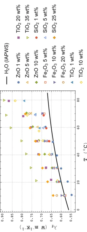
3.2 Thermal conductivity data of the HTFs . . . 49
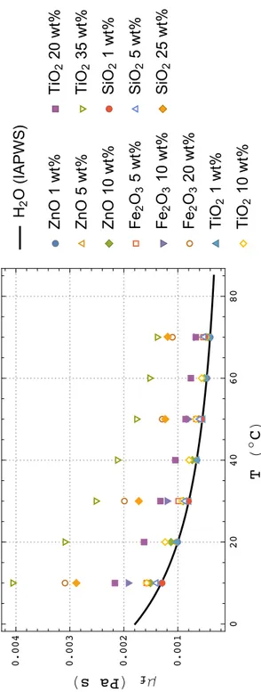
3.3 Dynamic viscosity data of the HTFs . . . 50
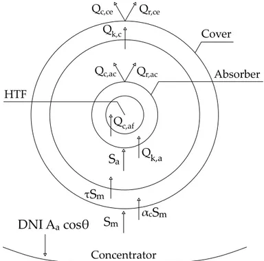
3.4 Energy balance for the cross-section of the collector . . . 52
3.5 Thermal resistance model of the receiver . . . 53
3.6 Calculated and experimental results for UNIVPM.01 . . . 56
3.7 Calculated and experimental results for UNIVPM.02 . . . 57
3.8 A possible connection scheme for the PTC field . . . 58
3.9 Yearly energy difference as a function of the inlet fluid temperature . . 61
3.10 Yearly energy difference as a function of the mass flow rate . . . 64
3.11 Convective heat transfer coefficient vs. inlet fluid temperature . . . 65
3.12 Yearly yield of TiO2+H2O at 1 wt% . . . 68
4.1 A picture of the solar box cooker prototype . . . 72
4.2 Solar box cooker prototype views . . . 74
4.3 Solar box cooker prototype sections . . . 75
4.4 Solar box cooker optical scheme . . . 76
4.5 Painted cooking chamber and vessel support . . . 78
4.6 Dodecagonal upper frame . . . 79
4.7 External structure . . . 79
4.8 Silicate blocks installed in the small door cavity . . . 80
4.9 Vermiculite inserted in the small door cavity . . . 81
4.10 Overall spectral reflectance of the booster mirrors . . . 82
4.11 Solar box cooker test bench . . . 83
4.12 Test without load . . . 87
4.13 Water load test . . . 88
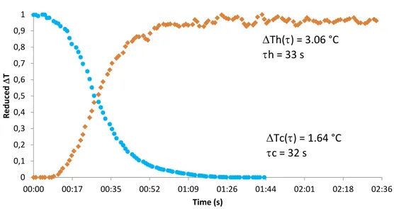
4.14 Water temperature trend . . . 89
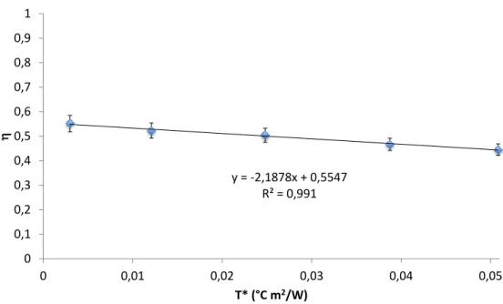
4.15 Standard cooking power as a function of temperature difference . . . . 91
4.16 Peanut oil load test . . . 92
4.17 Standard cooking power using peanut oil . . . 93
4.18 Thermal efficiency . . . 94
A.1 Solar angles for a tilted surface . . . 100
A.2 Beam radiation on horizontal and tilted surfaces . . . 103
A.3 Cross-section of a PTC . . . 104
A.4 Optical errors in a PTC . . . 106
A.5 Ineffective aperture area due to end effects . . . 109
A.6 End effects when the receiver extends beyond the trough . . . 110
A.7 Reflection and refraction at the interface of two media . . . 111
A.8 Radiation transfer between the glass and the absorber . . . 112
A.9 Energy balance for a PTC receiver cross-section . . . 113
A.10 Thermal resistance model of the receiver . . . 114
B.1 Closed-loop testing configuration for liquid solar collectors . . . 126
List of Tables
1.1 Solar energy collectors . . . 42.1 Characteristics of the UNIVPM.02 mold . . . 27
2.2 Layers used in the UNIVPM.02 concentrator structure . . . 28
2.5 Comparison of different PTC parameters . . . 40
3.1 Heat fluxes involved in the energy balance of the receiver . . . 54
3.2 Inputs used for the validation of the simulation environment . . . 55
3.3 Deviations between calculated and experimental efficiencies . . . 55
3.4 Composition of the TMY for Ancona . . . 58
3.5 Geometry and properties of the PTC field materials . . . 59
3.6 An extract of the heat demand profile . . . 60
3.7 Monthly and yearly yield at 40◦Cand 0.5 kg/s . . . . 62
3.8 Monthly and yearly yield at 80◦Cand 0.5 kg/s . . . . 63
3.9 Fluid temperature and efficiency for 40, 50, 50 and 70◦Cat 0.5 kg/s . 69 3.10 Fluid temperature and efficiency for 0.5, 1, and 1.5 kg/s at 80◦C . . . 70
4.1 Geometrical dimensions of the cooker . . . 77
4.2 Silicate properties . . . 80
4.3 Vermiculite properties . . . 81
4.4 TC-08 data logger specifications . . . 84
4.5 Water load test summary . . . 90
4.6 Peanut oil load test summary . . . 95
4.7 Comparison with literature . . . 96
A.1 Heat fluxes involved in the energy balance of the receiver . . . 114
A.2 Constants for air as annulus gas . . . 117
Abstract
Use of solar thermal energy has to be sustained to reduce consumption of climate-changing fossil fuels. Thus, in this study two concentrating solar prototypes were designed and manufactured: a parabolic trough collector (PTC) and a solar box cooker.
The PTC has a 90° rim angle and a concentration ratio of 19.89. The concentrator is a sandwich composite structure with high-reflectance aluminum foils applied on it. The receiver is a steel pipe painted with a selective coating. The tracking system is based on a solar-position computer program. Experimental tests were carried out with
water and temperatures up to 85◦C. Thermal efficiency, incident angle modifier, and
time constant curves were found. Results show that the thermal efficiency equation is comparable with that of other PTCs in literature.
Experimental data were utilized to validate a simulation environment able to determine the yearly yield of PTCs. The simulation was carried out to evaluate the convenience in adopting metal-based nanofluids respect to the base fluid (water). Five inlet fluid temperatures and three mass flow rates were analyzed. Results show that
only Au, TiO2, ZnO, and Al2O3 nanoparticles, at the lowest concentrations, present
reduced improvements respect to water.
The solar box cooker is a high concentration ratio prototype (11.57). The cooker has a cooking chamber with a glass cover on the top and is composed by two rows of booster mirrors. The prototype allows both a solar azimuth and zenith manual orientation. Tests without load were carried out to evaluate the maximum cooker temperature. Tests with load, conduced using aluminum vessels containing a certain amount of water, were accomplished both with non-painted vessels and black-coated ones, and with one or two vessels. Additional tests were carried out with peanut oil.
Using this fluid, temperatures higher than the water ones were achieved (> 200◦C)
and results exhibited values comparable to those in literature.
Sommario
L’utilizzo di energia solare termica deve essere sostenuto per ridurre il consumo di fonti fossili climalteranti. Nel presente studio si sono progettati e realizzati due sistemi solari a concentrazione: un collettore parabolico assiale (PTC) ed un forno solare a scatola.
in alluminio ad elevata riflettanza. Il ricevitore è un tubo di acciaio rivestito da una vernice selettiva. Il sistema di inseguimento è governato da un algoritmo solare. I test sperimentali sono stati condotti con acqua ad una temperatura massima di
85◦C. Il PTC è stato caratterizzato ottenendo curve di efficienza termica, modificatore
dell’angolo di incidenza e costante di tempo. I risultati mostrano che l’equazione dell’efficienza termica è confrontabile con quella di collettori simili.
I dati sperimentali sono stati utilizzati per validare un ambiente di simulazione della resa annuale di PTC. Si è determinata la convenienza nell’adozione di nanofluidi a base di metalli rispetto al fluido di base (acqua). Sono state analizzate 5 temperature del fluido in ingresso e 3 portate in massa. I risultati mostrano che solo le nanoparticelle di Au, TiO2, ZnO e Al2O3 alle più basse concentrazioni presentano ridotti miglioramenti. Il forno solare a scatola ha un rapporto di concentrazione di 11,57, ed è costituito da una camera di cottura, un coperchio superiore vetrato e una doppia fila di specchi riflettenti. Il prototipo consente un allineamento solare manuale sia azimutale che zenitale. La temperatura massima del forno è stata determinata attraverso prove a vuoto. Sono state inoltre svolte prove a carico inserendo nel forno una o due pentole di alluminio, verniciate o meno in nero, riempite con acqua o olio di arachidi. In
quest’ultimo caso, si è giunti a temperature superiori a 200◦Ce a risultati confrontabili
con quelli in letteratura.
Inde cibum coquere ac flammae mollire vapore sol docuit, quoniam mitescere multa videbant verberibus radiorum atque aestu victa per agros. — Titus Lucretius Carus, De rerum natura V, vv. 1102–1104
Acknowledgments
Firstly, I would like to thank Prof. Giovanni Di Nicola for his assistance, support, and collaboration during my doctoral carrier. I am grateful to Dr. Giulio Santori and Eng. Adio Miliozzi, who accepted to spend their time and efforts to review this thesis. I thank Eng. Miliozzi for his kind technical support on phase change materials, too.
My thanks also go to all the people who have worked with me in this period: my colleague Dr. Mariano Pierantozzi, the technicians of DIISM (Department of Industrial Engineering and Mathematical Sciences), the ICT (Institute of Construction Technologies) researchers of Padua (Italy), and all the students with whom I had the pleasure to share my experience. In particular, I’d like Eng. Giuliano Giuliani, Gabriele Gabrielli, and Gaetano Borrelli to know I appreciated their help with my experimental activities; the same feeling is addressed to Dr. Laura Colla, Dr. Laura Fedele, and Dr. Sergio Bobbo. As concerns students, I would like to express my special gratitude to everyone who has contributed to realize some parts of this thesis. I have decided not to report the entire list of people involved, as it would be extremely long. I hope this decision will be understood by everyone.
My special thanks go to Eng. Gianni Crovatto too, for his appreciated advices about solar cookers, and to Ms. Debra Tranquilli, for her priceless help in the English revision of the thesis.
In addition, I cannot forget to be grateful to Eng. Marco Sotte, Ph.D., who, in DIISM, originally undertook an experimental program called PTC.project. This program marked the beginning of my work on parabolic trough collectors.
Finally, I would like to thank my parents for all their continuous assistance and support; without them, I doubt that this work could have existed.
Ancona, Novemeber 2016 G. C.
Introduction
Global energy demand, and thermal energy demand in particular, is continuously increasing. In order to reduce consumption of climate-changing fossil fuels, use of renewable sources such as solar thermal energy has to be encouraged and sustained.
Thus, this thesis is focused on concentrating solar collectors, systems able to convert solar energy into heat through the utilization of special reflective mirrors and other optical devices. There are various types of solar collectors; this manuscript shows the work developed on prototypes of parabolic trough collector (PTC) and solar box cooker. Both the devices were intended to be used for low and medium enthalpy (or
low and medium temperature) demands, for temperatures up to about 85 and 300◦C
for the PTC and the box cooker, respectively.
The manuscript is divided into five chapters. The state of the art is presented in
Chapter1, which is about solar thermal engineering fundamentals and classification
of solar collectors and cookers available on the market. PTCs are usually classified by dividing them into two different parts: the concentrator and the receiver. Solar box cookers, instead, are presented as a specific classification of solar cookers. Solar thermal applications involving such devices are also discussed.
Chapter 2provides a detailed description of the PTC prototype design and
realiza-tion. This prototype, called UNIVPM.02, is a greater and more complex version of the previous one, UNIVPM.01. Both the PTCs were designed and manufactured in DIISM (Department of Industrial Engineering and Mathematical Sciences). UNIVPM.02 is a 90° rim angle PTC, having a concentration ratio of 19.89. The concentrator structure is based on a sandwich composite composed by two inside fill components: fiberglass as reinforcing material and low-density polyvinyl chloride (PVC) as matrix. The external shell was gel-coated. Aluminum reflective foils with high reflectance in the solar spectrum were applied on the concentrator surface to focus solar radiation in the parabola focal line. The receiver, placed in the focal line, is a not-evacuated steel circular tube, painted with a selective coating. In this way, absorption of solar energy was augmented and radiative heat losses with the environment were reduced. The tracking system, operated by an electric engine, can be manual or automatic. In this last case, the concentrator rotation is ruled by a solar tracking algorithm. The design and manufacturing processes are firstly introduced then, the test bench used to evaluate the collector thermal efficiency is reported. Tests were performed according to the directives of ANSI/ASHRAE Standard 93-2010 and using demineralized water
at temperatures up to 85◦C. The equation obtained for the thermal efficiency is
comparable to that of other similar collectors available in literature.
A way to improve a low-enthalpy PTC thermal efficiency could lie in the adoption of heat transfer fluids alternative to water. Thus, nanofluids, i.e. solutions composed by a base fluid (e.g., water) and a solute uniformly dispersed in form of solid particles with nanometric dimension, were studied. Different types of nanoparticles were analyzed in
stable, a reduced quantity of nanoparticles could have the potential to increase the
thermal properties of the base fluid. In Chapter 3, the results of thermal conductivity
and dynamic viscosity measurements, carried out for six water-based nanofluids, are
reported. The nanoparticles under study were: Fe2O3 (5, 10, 20 wt%), SiO2(1, 5, 25
wt%), TiO2 (1, 10, 20, 35 wt%), ZnO (1, 5, 10 wt%), Al2O3 (0.1, 1, 2 wt%), and Au
(0.01 wt%). A simulation environment, built to evaluate the yearly yield of a nanofluid-based PTC, is then presented. The inputs of the simulation environment include fluid and material properties, geometrical features of the systems, plant working conditions, sun position, and a hourly-resolution typical meteorological year. The mathematical model of the simulation environment was validated through experimental tests carried out on the prototypes UNIVPM.01 and UNIVPM.02. The model was coupled with a specific low-temperature heat demand profile: 5 inlet fluid temperatures (40, 50,
60, 70, 80◦C) and 3 mass flow rates (0.5, 1, 1.5 kg/s) were analyzed. Results, which
are provided through a direct comparison with water, prove that there is no general convenience in adopting nanofluids, at least for the low-temperature applications under study.
The design, manufacture, and testing of a prototype of solar box cooker is presented
in Chapter4. This prototype, based on a freeware design, has a concentration ratio of
11.57 and was manufactured in DIISM. It was modified in some components (absorber coating, reflecting mirrors, glass double cover, insulation material) to increase thermal insulation and optical efficiency. The cooker is composed by an internal metal box used as cooking chamber, with a glass cover on the top. In the higher part of the container, there is a double row of mirrors. Each row has a different inclination angle respect to the horizontal plane. The cooker has two border wooden hands and two wheels that allow its movement and its azimuth orientation. Moreover, a zenith orientation is possible thanks to a rotation around the horizontal axis. In the cooking chamber, there is a rotating vessel support able to rotate of 360°, so that it can maintain in balance the vessels put on it when the zenith orientation changes.
The test bench used for the oven characterization was realized to satisfy different experimental procedures available in literature. Two kinds of experimental test were carried out: with and without load. Tests without load allowed to evaluate the maximum temperature of the cooker. Tests with load, otherwise, were conduced putting in the cooking chamber aluminum vessels (18 cm diameter and 16 cm high) able to contain about four liters of fluid. Such tests were done both with non-painted vessels and black-coated ones, in order to evaluate the differences in performance. In addition, experimental tests with one vessel containing water and with two vessels containing the same amount of fluid were carried out. Results showed some differences respect to the procedures usually followed in literature; these differences could be due to the high insulation level of the cooker. In order to deeply investigate this behavior, an additional type of tests was conduced, using one and two black-painted vessels filled with peanut oil instead of water. In this case, temperatures higher respect to water
(> 200◦C) were achieved, and results exhibited not only values comparable to those in
literature, but also considerable performances.
Finally, Chapter 5reports some critical conclusions and future advancements of
the work presented.
In order to give a complete overview on solar collectors, AppendixAand AppendixB
describe a complete mathematical model for PTCs and the available standards used to test these solar collectors, respectively.
Chapter 1
Overview on Solar Thermal
Energy
In this introductory chapter, fundamentals of solar thermal energy are discussed. Further, solar thermal collectors and solar cookers, devices able to convert solar energy into heat, are briefly presented. Among these, parabolic trough collectors (PTCs) and solar box cookers, which are the main subjects of this thesis, are introduced. PTCs are usually studied by dividing them into two different parts: the concentrator and the receiver. Instead, solar box cookers are presented as a specific classification of solar cookers, which can fall within several categories. The materials used in such devices and their working principle are also discussed. Finally, typical solar thermal applications are presented, in particular as regards their utilization with PTCs and solar box cookers.
1.1
The Role of Heat and Solar Thermal Energy
The growth in energy consumption over the past 20 years has been significant and demand for energy will continue to grow due to global population increase. Even though the demand for electric energy is generally considered of maximum importance, civil and industrial processes based on heat are not less relevant. A paper published
by IEA (International Energy Agency) in 2014 [1] underlines that, nowadays, the
production of heat accounts for more than 50% of global final energy consumption. One of the most important aspects of such sector is that heat use per capita varies considerably less than total energy use per capita between different world regions. This means that the need of thermal energy has a fundamental impact in all countries. Global energy use for heat in industry, buildings, and other sectors reached 172 EJ in 2011. About three-quarters (129 EJ) of global energy use for heat processes is met
with fossil sources, leading to around 10 Gt of CO2 emissions per year, one third of
the global total in the energy sector.
In Europe, two-thirds of the energy demand consists of heat, and it is confirmed that about 50% of this heat demand (estimated at about 300 TWh in 2000) is
required at temperatures up to 250◦C[2]. The global commercial low-temperature
heat consumption is estimated to be about 10 EJ per year only for hot water production
[3]. The only way to meet that global heat demand without contributing to climate
change and environmental problems implies the utilization of renewable sources. 1
Several renewable heating technologies are already mature and can provide heat at costs competitive with fossil fuel-based heat in an increasing number of circumstances,
thus providing a way to enhance energy security and reduce energy-related CO2
emissions. Renewable energy accounts for 43% (36 EJ) of total energy use for heat in buildings, while in the industry sector, it accounts for 10% of the total. However, in both cases, most of heat comes from the use of traditional bioenergy. Only 4 EJ are currently produced by more sustainable renewable energy technologies: the largest contribution (3 EJ) comes from modern bioenergy, while a reduced amount derives from the use of solar thermal (0.7 EJ) and geothermal energy (0.3 EJ). In particular, solar thermal energy use for heat is growing rapidly in a number of countries: with 12% annual growth from 2000 to 2011, solar thermal energy is the fastest growing renewable energy source used for heat in the buildings sector.
Solar energy is the most abundant permanent energy resource on earth. One of the most popular low-temperature application of solar system is domestic water heating. Beyond the domestic applications, solar energy has several potential fields of application for low-temperature industrial processes. A wide range of collectors can be used for these low-temperature applications: flat plate, evacuated tube, compound parabolic, and more advanced types such as parabolic trough collectors (PTCs), which appear
to be one of the most promising technologies to use the energy of solar radiation [4].
Low-temperature (or low-enthalpy) PTCs could provide thermal energy to domestic applications (e.g., domestic water heating, space heating, and cooling) and to industrial processes (e.g., pressurization, boiler feed-water, preheating water, pasteurization,
cooking, etc.) at temperatures up to about 100◦C[5].
Among the application of solar thermal energy, solar cooking is considered as one
of the simplest and attractive ways of the utilization of solar energy [6]. Energy for
cooking is one of the fundamental uses in developing countries. Wood is still the primary energy source in much of the development world because of its cheapness; this situation is responsible for some serious ecological problems, especially deforestation. In most of rural areas of Africa, the energy demand for cooking is supplied by non-commercial fuels (e.g., firewood, agricultural waste, cow dung, kerosene); in India, the energy required for cooking accounts for 36% of total primary energy consumption and
90% of rural households depend on biomass fuels [7]. In addition to the environmental
and economic issues, the firewood use also causes some serious health problems such as burns, eye disorders, and lung diseases.
However, considering that in most of the developing countries of the world there
is abundance of solar radiation (a mean daily solar radiation of 5-7 kWh/m2 and
more than 275 sunny days in a year have been estimated [8]), it is clear that solar
cookers represent in such countries a possibility to meet the energy demand in the domestic sector. Other advantages of solar cookers are reduction of costs and drudgery, high nutritional value of food, and high durability. Unfortunately, the large-scale dissemination of solar cookers still remains limited; such devices are diffused all over
the world, but most of them are intended for research purposes only [9]. The main
obstacles to the dissemination of the technology are the resistance to acceptance as it is a new technology, variable nature of solar radiation, limited space availability in
1.2. SOLAR THERMAL COLLECTORS 3
1.2
Solar Thermal Collectors
The principle usually followed in solar thermal energy collection is to expose a dark surface to solar radiation so that this one is absorbed. A fraction of this absorbed radiation is then transferred to a heat transfer fluid (HTF) such as water or air.
Solar collectors can be divided into stationary (or non-concentrating) and concen-trating systems. The main difference between them is that the former have the same area for intercepting and absorbing solar radiation, while the latter generally have reflecting/refracting surfaces which intercept and focus the solar beam radiation to a smaller receiving area, thus resulting in an increased radiation flux.
Stationary collectors are permanently fixed in a certain position and are not able to follow the sun. Collectors which fall into this category are:
• flat plate collectors (FPCs); • evacuated tube collectors (ETCs); • solar air heaters.
When higher temperatures are required, solar radiation needs to be focused. This is achieved by using concentrating collectors. Solar radiation can be concentrated by interposing a reflecting arrangement of mirrors or a refracting arrangement of Fresnel lenses between the source of radiation and the absorber surface. The level of concentration is generally described by a quantity referred to as concentration ratio,
C, which is defined as the ratio between the aperture area of the collector, Aa, and its
receiver area, Ar:
C= Aa
Ar (1.1)
The optical system which directs the solar radiation on to the absorber is defined concentrator, while the system including the absorber, its cover, and other accessories is defined receiver. The reflecting surfaces may be parabolic, spherical, or flat and continuous or segmented. Also, they can be classified according to the formation of the image, being either imaging or non-imaging. Imaging concentrators may focus on a line or at a point. The absorber can be convex, flat, or concave and it has a reduced area respect to that of the reflecting/refracting system. In addition, it can be uncovered or surrounded by a transparent cover.
The presence of the optical system compromises the overall performance by adding several inefficiencies:
• reflection losses; • absorption losses;
• losses due to geometrical imperfections of the optical system.
However, the introduction of these inefficiencies is compensated for by the fact that the area from which heat losses occur (i.e., that of the absorber) is considerably reduced. From an engineering point of view, concentrating collectors present additional problems to those of stationary collectors. In fact, because of the presence of the optical system, concentrating collectors have to be oriented to follow or track the sun in order to have the beam radiation directed on to the absorber surface. Different tracking methods are possible, and a proper choice depends on the precision with which it has to be done:
Table 1.1: Solar energy collectors (as reported by Kalogirou [5]).
Type Tracking Absorber C Temperature range
(◦C)
FPC Stationary Flat 1 30 ÷ 80
ETC Stationary Flat 1 50 ÷ 200
CPC Stationary Tubular 1 ÷ 5 60 ÷ 240 One-axis Tubular 5 ÷ 15 60 ÷ 300 PTC One-axis Tubular 10 ÷ 80 50 ÷ 400 LFR One-axis Tubular 10 ÷ 40 60 ÷ 250 PDR Two-axis Point 600 ÷ 2000 100 ÷ 1500 HFC Two-axis Point 300 ÷ 1500 150 ÷ 2000
• in collectors with a low concentration ratio, it is often adequate to manually make one or two adjustments of the collector orientation every day;
• in collectors with a high concentration ratio, a continuous adjustment of the collector orientation is necessary.
Tracking may be required around one or two axis. Obviously, the necessity of a tracking method introduces complexity in the design, and maintenance requirements are also increased; all these factors weight on the costs. In addition, the almost entirely part of diffuse radiation is lost being not focused. Compared to FPCs, there are few manufacturers of concentrating collectors all over the world, and the volume production
is low [11].
A classification of solar collectors available on the market is provided in Table 1.1.
1.2.1
Flat Plate Collectors
Flat plate collectors (FPCs) are the most important and widely used type of solar collectors because they are simple in design, have no moving parts, and need little maintenance. From a mechanical point of view, they are much simpler than concentrating collectors and they can be used for applications where temperatures
range from 40 to 100◦C[11].
A FPC using a liquid as HTF (Heat Transfer Fluid) is shown in Figure 1.1. The
liquid heated is generally water, but sometimes mixtures of water and ethylene glycol
are used if ambient temperatures below 0◦Care encountered. A FPC consists of four
components:
• an absorber plate, usually made from a thin metal sheet;
• tubes fixed to the absorber plate through which the HTF flows, made of metal; • a cover transparent to the incoming solar radiation and, at the same time, opaque
to long wavelength radiation emitted by the absorber plate;
• a collector box, usually made of aluminum with an epoxy coating on the outside for protection.
Solar radiation falls on the absorber plate after crossing the transparent cover. The absorbed radiation is partially transferred to the liquid flowing through the tubes.
1.2. SOLAR THERMAL COLLECTORS 5
Figure 1.1: Schematic of a liquid flat plate collector (FPC) [12].
This heat transfer represents the useful gain. The remaining part of the radiation absorbed in the absorber plate is lost by convective and radiative heat transfers to the surroundings from the top surface, and by the conductive heat transfer through the back and the edges. The cover helps in reducing the losses by convection and radiation, while thermal insulation on the back and the edges, generally made with mineral wool, rock wool, or glass wool, allows to reduce the conductive loss.
A selective coating can be put on the absorber plate for reducing heat lost by radiation and improving the efficiency. To reach this goal, the selective coating must exhibit high absorptance in the range of solar spectrum and reduced emissivity in the range of mid/long infrared.
The main advantage of a FPC is that it utilizes both the beam and diffuse com-ponents of the solar radiation. On the other hand, its principal disadvantage is that the collection area is large because there is no optical concentration; therefore, the efficiency is generally low.
1.2.2
Evacuated Tube Collectors
Further enhancements in the efficiency of a FPC can be obtained by evacuating the volume between the absorber plate and the cover. In this way, the heat losses by convection from the top to the surroundings are reduced. Most practical designs are based on glass tubes because only a tubular surface can provide the structural strength to withstand the stresses introduced by the pressure difference.
A device with the above mentioned design is called ETC (Evacuated Tube Collector). It consists of a number of long cylindrical FPCs modules side-by-side. Each module is an evacuated, cylindrical glass tube containing a metal absorber plate with a selective coating. A U-tube heat removal system is attached to the absorber plate:
an arrangement of this type is shown in Figure1.2a. The incoming solar radiation is
absorbed on this surface and partially transferred by conduction to the U-tube, then by convection to the HTF. A glass-to-metal seal is provided at the end cover of the glass tube.
The need of a seal, which is difficult to maintain, can be eliminated by adopting
(a)Evacuated tube with U-tube removal system.
(b)Double-walled evacuated tube.
Figure 1.2: Designs of evacuated tube collectors (ETCs) [12].
case, each module consists of a long evacuated tube having the outer surface of the inner tube as the selective absorber. Other possible designs include the utilization of heat pipes. Thanks to the suppression of convective losses and the provision of a selective surface, ETCs can exhibit an efficiency significantly higher than that of conventional collectors.
1.2.3
Solar Air Heaters
A FPC used to heat air is referred to as solar air heater. The construction of this collector is similar to that of a liquid FPC, except for the passages where the air flows. In fact, these passages have to be made larger in order to keep the pressure drop across the collector limits. For this reason, a conventional solar air heater generally consists of an absorber plate with a parallel plate below forming a passage through which the air flows. A transparent cover is provided above the absorber plate, and a sheet metal container filled with insulation is provided on the bottom and sides. Materials of construction and sizes are similar to those adopted with FPCs. However, plastics
are being used in increasing numbers [11].
Solar air heaters are simple in design and require little maintenance. Also, they can
operate below 0◦Cbecause air does not freeze, and corrosion and leakage problems
are less severe. On the other hand, the convective heat transfer between the absorber plate and the air is low, thus a lower efficiency is obtained. To overcome this problem, surfaces are often roughened or longitudinal fins are provided in the air-flow passage. Another disadvantage is that large volumes of fluid are required, thus resulting in significant electrical inputs, especially if pressure drops are not kept within prescribed limits.
Compared to FPCs, commercialization of solar air heaters has been slow all over
the world. According to Sukhatme and Nayak [11], in India the reason is the fact that
1.2. SOLAR THERMAL COLLECTORS 7
Figure 1.3: Cross-section of a compound parabolic collector (CPC) [12].
of agricultural products; being this one a seasonal activity, the drying systems remain idle for a large part of the year and the payback period is poor. A more attractive market for solar air heaters could be the utilization for industrial purposes and space heating.
1.2.4
Compound Parabolic Collectors
This non-imaging collector consists of curved segments facing each other that are
parts of two parabolas (Figure1.3). A compound parabolic collector (CPC) is capable
to reflect to the absorber all the incident radiation within wide limits. In fact, the main advantage of CPCs is that they have high acceptance angles and require only occasional or intermittent tracking. By using multiple internal reflections, any radiation entering the collector acceptance angle reaches the absorber surface located at the bottom of the collector. The absorber can be flat, bi-facial, wedge, or cylindrical.
The concentration ratio is generally low, ranging from 3 to 10, and is equal to the maximum value possible for a given acceptance angle. CPCs can be manufactured either as one unit with one opening and one receiver or as a panel, in this case being
similar to a FPC [5]. No significant commercial development has taken place [11].
1.2.5
Parabolic Trough Collectors
A schematic of a line-focusing concentrating collector, also referred to as PTC
(Parabolic Trough Collector), is shown in Figure1.4. This collector consists of:
• a concentrator, including the reflector and the support structure;
• a receiver, that includes the absorber tube located at the focal axis through which the HTF flows, and the transparent cover.
The reflector is a mirror having the shape of a cylindrical parabola, and it concentrates the beam radiation on to its focal axis, where it is absorbed on the absorber tube
Figure 1.4: Schematic of a parabolic trough collector (PTC) [12].
surface and transferred to the fluid flowing through it. The concentrator must rotate about its axis to let the beam radiation to be focused on the absorber tube.
The reflective surface is generally made of a curved back silvered glass, fixed on a light-weight structure. The support structure should not distort significantly due to its own weight and it should be able to withstand wind loads.
The absorber tube is generally made of stainless steel, copper, or aluminum and
has a diameter of 25 to 50 mm [11]. It is coated with a heat resistant black paint.
The concentric glass cover has usually an annular gap of 10 or 20 mm and allows to reduce radiative and especially convective losses to the surroundings. To improve performances, the absorber tube can be coated with a selective paint and the annulus can be evacuated.
These collectors are available over a wide range of aperture areas from about 1
to 60 m2, and widths from 1 to 6 m. Fluid temperatures between 50 and 400◦C, and
concentration ratios ranging from 10 to 80 can be obtained [11].
1.2.6
Fresnel Collectors
Concentration may be also achieved by adopting lenses. One of the most common
device is the Fresnel lens. Fresnel collectors have two variations, as shown in Figure1.5:
• Fresnel lens collector (FLC, Figure1.5a). It is usually a thin sheet, flat on one
side and with fine longitudinal grooves on the other; these grooves are disposed so that radiation is brought to a line focus. The lens are generally made of extruded acrylic plastic sheets.
• Linear Fresnel reflector (LFR, Figure 1.5b). It is an array of linear mirror strips
that concentrate the solar radiation onto a linear receiver. It can be imagined as a broken-up PTC, but the individual strips do not need to be of parabolic shape. The strips of LFRs can also be mounted on ground and focus the solar radiation on a linear fixed receiver mounted on a tower. In this case, larger absorbers can be adopted. The greatest advantages of this arrangement are that reflectors are cheaper because they do not need to be parabolic and they can be mounted close to the ground, thus
1.2. SOLAR THERMAL COLLECTORS 9
(a)Fresnel lens collector (FLC).
(b)Linear Fresnel reflector (LFR). Figure 1.5: Fresnel collectors [5].
One difficulty with LFRs is that avoidance of shading and blocking between adjacent reflectors leads to an increased spacing between reflectors themselves. Blocking can be reduced by adopting higher absorber towers, but this increases costs. Fresnel collectors can achieve concentration ratios between 10 and 80, and yield temperatures between
150 and 400◦C[11].
1.2.7
Paraboloid Dish Reflectors
Still higher temperatures can be reached by adopting PDRs (Paraboloid Dish
Re-flectors), concentrating systems having a point focus rather than a focal line. Figure1.6
shows the schematic of a PDR. This system has a concentrator that tracks the sun by rotating about two axes. Thus, the solar beam radiation is brought to a point focus, so that the sun is in line with the focus and the vertex of the paraboloid. A HTF flowing through a receiver at the focus is heated and this heat is typically used to drive a Stirling engine.
The receiver is an important component of PDRs. It is difficult to design because it
Figure 1.6: Schematic of a paraboloid dish reflector (PDR) [5].
it, and transfer the energy to the engine HTF. For all of these reasons, a number of
new ideas have been tried out [11]:
• heat pipes using liquid metals like sodium, used to transfer the heat from the receiver to the engine head;
• hybrid receivers which can absorb both solar energy and energy from other sources (e.g., fossil fuel or bio-gas);
• volumetric receivers similar to those used in heliostat field collectors (see Sec-tion1.2.8).
These collectors can have concentration ratios ranging from 100 to a few thousand,
and yield temperatures up to 2000◦C[11]. However, there are limitations to the size
of the concentrator and hence the amount of energy that can collected by one dish.
Commercial versions have been built with dish diameters up to 17 m [11].
1.2.8
Heliostat Field Collectors
In order to collect larger amounts of energy at one point, HFCs (Heliostat Field
Collectors) have been developed. In this type of concentrating collector (Figure1.7),
solar radiation reflected from an array of large mirrors called heliostats is focused on a receiver located at the top of a tower. The orientation of the heliostats is individually controlled so that throughout the day they reflect direct radiation on the receiver.
The heliostats form an array of circular arcs around the central tower. Their function is to intercept, reflect, and focus the solar radiation on the receiver. They are generally served by a two-axis tracking control system; when the solar radiation is not being collected, the control system orients the heliostats in a safe direction in order to protect the receiver. Degradation of the mirrored surfaces of the heliostats and low availability of the heliostats are major issues in the development of these collectors. Also, the costs of the heliostats and of their control systems form a significant part (≃ 40 ÷ 50%) of the initial investment. For these reasons, new concepts have been proposed, e.g. the utilization of larger size glass-mirrors, or heliostats using a stretched
1.2. SOLAR THERMAL COLLECTORS 11
Figure 1.7: Heliostat field collectors (HFCs) [12].
The receiver is the most complex part of the system. The principal factor that influences its design consists of its ability to accept the large and variable heat flux that results from the solar concentration by the heliostats. The value of the heat flux can
achieve 1000 kW/m2, resulting in high temperatures, thermal gradients, and stresses
in the receiver. For these reasons, the absorber shape, the HTF, the arrangement of tubes carrying the fluid, and the materials adopted need to be chosen with particular
attention [11].
1.2.9
Solar Ponds
Devices that combine the functions of both solar energy collection and storage are called solar ponds. They consist of a large expanse of water of about 1 or 2 m in depth where salts like sodium or magnesium chloride are dissolved, in order to maintain a
concentration gradient. These devices are referred to as salt-gradient solar ponds [11]
and are shown in Figure1.8. The concentration of the salt is more at the bottom and
less at the top; in this way, the bottom layers of water are denser than the surface layers even if they are hotter, and free convection does not occur. Therefore, absorbed solar energy at the bottom of the pond is retained in the lower depths, and the upper layers of water act like a thermal insulation.
In the last 40 years, many salt-gradient solar ponds have been built in a number of countries, both for experimental and demonstrative purposes. The indications are that they would be economical for applications requiring low temperature processes up to
70or 80◦C[11]. However, long-term operation and maintenance are problems of main
Figure 1.8: A salt-gradient solar pond [12].
1.3
Solar Cookers
Solar cookers (also called solar ovens) are devices able to cook food by utilizing solar energy. These devices can be used for processes such as pasteurization and sterilization, too. In the world, there are many arrangements of solar cookers and a comprehensive classification is not easy to be done. However, solar cookers can be broadly classified
into two groups [10]:
• solar cookers without storage; • solar cookers with storage.
Solar cookers without storage are categorized under direct and indirect solar cookers depending upon the involved heat transfer processes. Direct solar cookers use solar radiation directly in the cooking process, while indirect solar cookers use a working fluid to transfer the heat from the collector to the cooking device. As in indirect solar cookers the pot is physically displaced from the collector and flat plate collectors, evacuated tube collectors, and concentrating collectors are usually adopted to collect solar energy, this type of solar cookers will not be further analyzed in this thesis.
Instead, direct solar cookers are usually classified into the following two types [10]:
• box cookers;
• concentrating cookers.
Figure1.9summarizes the proposed classification of solar cookers.
1.3.1
Box Cookers
The first invented solar cooker was a box-type and was invented in 1767 by a
French-Swiss naturalist called Horace de Saussure [6]. In the last decades, box cookers
1.3. SOLAR COOKERS 13
Figure 1.9: A classification of solar cookers. Adapted from Muthusivagami et al. [10]. A solar box cooker consists of an insulated box with a transparent glass cover and
mirrors to reflect direct solar radiation into the box, as shown in Figure1.10. The
inner part of the box is usually painted in black in order to maximize the absorption of solar energy. Even if solar box cookers are slow to heat up, it was noted that they work well even with diffuse radiation, wind, intermittent cloud cover, and reduced
ambient temperatures [13]. Additional advantages of box cookers include simplicity
of manufacture and operation with minimal attendance required during the cooking process. This kind of cooker is also more stable and can keep food warm for a long period of time.
The payback period of a common solar box cooker, even if used 6–8 month a years,
was found to be around 12–14 months [14]. Even with booster mirrors, solar box
cookers have concentration ratios up to 10 and they rarely reach temperatures above
100◦C[10].
1.3.2
Concentrating Cookers
In concentrating solar cookers, the cooking vessel is placed at the focus of a concentrating mirror. These solar cookers can work with one or two axis tracking and
can reach concentration ratios up to 50 and temperatures up to 300◦C. However, they
have disadvantages such as size, cost, the risk of fires and burns, frequent adjustments to track the sun, and the impossibility to use thermal storage units for cooking during off-sunshine periods. Concentrating cookers include panel, funnel, spherical, parabolic,
Fresnel, and cylindro-parabolic type [10].
Solar panel cookers are the most available type of solar cookers because of their
ease of manufacture and low-cost materials [6]. They utilize reflective mirrors in order
to direct solar rays to a cooking vessel which is enclosed in a clear plastic bag (Figure
1.11). Their reduced dimensions make them highly appreciated by people living or
traveling alone. Performance of solar panel cookers strongly depends on reflected radiation, therefore they require clear-sky conditions to work properly; they are not very effective during cloudy days. Some solar panel cookers were also designed and
Figure 1.10: A solar box cooker [6].
Figure 1.11: A solar panel cooker [16].
manufactured for sterilization purposes [15].
The first parabolic cooker was developed by Ghai and Bansal [17] in the early 1950s
in India. This type of solar cooker can reach very high temperatures in a very short time and, unlike the panel and box cooker, they do not require a special cooking pot.
A typical solar parabolic cooker (Figure 1.12) consists of a parabolic concentrator with
a cooking pot located on the focus point of the cooker and a stand to support the
cooking system [6]. Parabolic cookers are the most widespread type of concentrating
cookers because the focus is much better and sharper than that of other types of
reflectors, but at the same time they require constant tracking [10].
1.3.3
Other Direct Solar Cookers
In recent years, research focused on studying and manufacturing novel designs of
solar cookers in order to provide better cooking efficiency [6].
1.3. SOLAR COOKERS 15
Figure 1.12: A solar parabolic cooker [9].
type solar cookers. Tiwari and Yadav [19] realized an alternative solar box cooker
integrated with a single reflector at the cover and found that it was more efficient
respect to a conventional cooker. In 1991, Al-Saad and Jubran [20] designed a
low-cost solar cooker made of clay and locally available materials. No skilled labor was needed and the absorber plate was replaced with locally available black stones, which
allowed energy storage and, thus, late cooking. Sonune and Philip [21] developed a
Fresnel concentrating cooker where the highest plate bottom temperature was found
to be 255◦Cin approximately 40 minutes when ambient temperature and direct solar
radiation were, respectively, 30◦Cand 859 W/m2. Kurt et al. [22] manufactured two
different models of solar box cookers, rectangular and cylindrical, and tested the effects of the box geometry on the performance. They found that the cylindrical model provided higher thermal efficiency and lower characteristic boiling time than the
rectangular type. Kumar et al. [23] designed and realized a truncated pyramid type
solar cooker that did not require a solar tracking system; the maximum stagnation
temperature was found to be 140◦Cand water temperature inside the cooker reached
98.6◦C in 70 minutes. Abu-Malouh et al. [24] designed, manufactured, and tested
a spherical type solar cooker coupled with an automatic sun tracking system; the
temperature inside the cooker reached more than 93◦Cin a day with a maximum
ambient temperature of 32◦C.
1.3.4
Solar Cookers with Storage
When a mismatch between the supply and consumption of energy exists, thermal energy storage is necessary. In order to cook when there are frequent clouds in the day or during off-sunshine hours, solar cookers must adopt a heat storage material to store thermal energy in form of sensible heat, latent heat, thermo-chemical heat, or a
combination of them [10].
In sensible heat storage, thermal energy is stored by raising the temperature of
a solid or a liquid. For the purpose, researchers used engine oil [8], sand [25], and
Figure 1.13: The latent heat storage unit designed by Sharma et al. [27].
heat capacity and the decrease in effectiveness of cooking since the temperature of the
storage material decreases rapidly during discharging [10].
Latent heat storage uses the energy stored when a substance changes from one phase to another. The use of PCMs (Phase Change Materials) for storing latent heat has been recognized to be a compact and efficient way because of their high storage
density and constant operating temperature [10]. Sharma et al. [27] designed and
realized a PCM storage unit made of two hollow concentric aluminum cylinders of
diameter 18 and 25 cm (Figure1.13). The gap between the cylinders was filled with
acetamide and the heat transfer rate between the PCM and the storage unit was enhanced by eight fins welded at the inner wall. They found that a second batch of food could be cooked if it was loaded before 15:30 and by using 2 kg of acetamide.
1.4
Solar Thermal Applications
Solar energy is used in a great number of thermal applications to meet various
energetic needs. These are [11,28]:
1. water heating; 2. space heating;
3. space cooling and refrigeration; 4. industrial process heat;
5. power generation; 6. distillation; 7. drying;
1.4. SOLAR THERMAL APPLICATIONS 17 8. cooking.
Most of the above applications use one or more of the devices described in the previous sections. The applications 1, 2, 4, 6, 7, and 8 use thermal energy collected from solar radiation directly, while the applications 3 and 5 use the heat collected in thermodynamic cycles to obtain cooling or electrical work. From an economic point of
view, applications that use heat directly are obviously more attractive [11].
1.4.1
Water Heating
Solar water heating is one of the most attractive solar thermal applications from an
economic standpoint [11]. In many countries of the world, this technology is already
competing on equal terms with systems using other energy sources. FPCs are the most
adopted collectors for this kind of application [11]. Hot water is generally used for
domestic, industrial, and commercial purposes.
Solar water-heating systems can be classified into two categories: • natural circulation (or passive, or thermosyphon) systems; • forced circulation (or active) systems.
The two main components of a natural circulation system are a liquid FPC and a storage tank. The last one is usually located above the collector level. As water in the collector is heated by solar radiation, it flows automatically to the top of the water tank and is replaced by cold water from the bottom of the tank. Hot water is withdrawn from the top of the tank. Natural circulation systems were used fairly widely in many countries from the beginning of the 20th century till about 1940 until cheap oil and natural gas became available. Today, passive systems are being installed again in large
numbers [11].
Domestic water heating systems based on ETCs are also adopted. These systems consist of a number of evacuated tube modules connected directly to the storage tank. The inner part of each module is filled with water, which gets heated up by the solar radiation. A thermosyphon circulation is then established: hot water flows out of each module and cold water from the storage tank takes its place.
When a large amount of hot water is required to supply industrial or commercial heat demands, a forced circulation system maintained with a water pump is adopted. In this case, there is no necessity to put the storage tank at a higher level. Water from the storage tank is pumped through a collector array, where it is heated and then flows back into the storage tank. Solar water systems of this type are well suited for
factories, hospitals, hotel, offices, etc. [11].
1.4.2
Space Heating
Space heating is of particular relevance in colder countries where a significant
amount of energy is required for the purpose [11]. Heat for comfort in buildings can be
provided by systems that are similar to water heating systems and can be distinguished into two types:
• active methods; • passive methods.
Active methods use pumps or blowers to circulate the HTF in the space-heating system. On the other hand, with passive methods thermal energy flows through a living space by natural means without a mechanical device help.
The use of passive techniques for heating, as well as ventilation and cooling, is not
new. They were adopted by almost all ancient civilizations [11]. However, passive
methods are not used extensively because do not provide the same degree of comfort as an active heating system. But it is worth noting that nowadays, with rising fossil fuel costs, people are realizing the possibilities offered by passive methods and they
are being slowly rediscovered [11]. In many new buildings, hybrid systems using both
passive and active methods are being considered; in this way, the size of the active system is considerably reduced.
Compared to flat plate collectors, solar air heaters can be a logical choice for these applications, because they eliminate the need to transfer heat from one fluid to another.
1.4.3
Space Cooling and Refrigeration
Cooling is one of the most interesting thermal applications of solar energy as it can be adopted to provide comfortable living conditions or food preservation. Since solar energy is received as heat, an obvious choice is a system working on the absorption refrigeration cycle which requires most of its energy input as heat. Cooling is required most in summer, thus a seasonal matching between the energy needs of the space cooling system and the availability of solar radiation is generally satisfied.
Unfortunately, the installation cost of a solar absorption refrigeration system is
high because of the cost of the large collector array required [11].
1.4.4
Industrial Process Heat
The most important application for solar energy at medium-high temperature
(80 ÷ 240◦C) is heat production for industrial processes, which represents a significant
amount of heat. Industrial heat demand constitutes about 15% of the overall demand
of final energy requirements in the southern European countries [5]. The heat demand
in the European Union for medium and medium-high temperatures is estimated to be
about 300 TWh/year [29].
Several industrial sectors were identified as having favorable conditions for the
application of solar energy [5, 28]:
• sterilizing; • pasteurizing;
• drying of lumber or food; • hydrolyzing;
• washing;
• cleaning in food processing;
• extraction operations in metallurgical or chemical processing; • curing of masonry products;
1.4. SOLAR THERMAL APPLICATIONS 19 • polymerization.
Temperatures for these applications can range from near ambient to those of low-pressure steam. Energy can be provided both from FPCs (for low-temperature applica-tions) and concentrating collectors (for medium-high temperatures). Industries which use most of the energy are food industry and manufacture of non-metallic mineral products. Favorable conditions exist in food industry because food treatment and
storage are processes with high energy consumption and running time [5].
PTCs are frequently adopted for solar steam generation since relatively high temperatures can be obtained with good efficiencies. Low-temperature steam can be used in industrial applications, sterilization, and for powering desalination evaporators.
Different methods were developed to generate steam by using PTCs [5].
Since solar energy is transient and intermittent, and investments in industrial processes are usually large, the choice of different arrangements in solar industrial applications can be done by using simulation methods at lower costs respect to the investments. In order to replace the utilization of large quantities of fossil fuels, solar
energy for industrial process heat may represent an interesting alternative [28].
1.4.5
Power Generation
The generation of electrical power is one of the most important applications of
solar energy [11]. Solar thermal power cycles can be classified as:
• low temperature cycles (<100◦C), using FPCs or solar ponds;
• medium temperature cycles (< 400◦C), using PTCs;
• high temperature cycles (> 400◦C), using either PDRs or HFCs.
Low temperature systems using FPCs generally work on a Rankine cycle. The overall efficiency of these systems are rather low, because the temperature difference between the steam leaving the generator and the condensed liquid leaving the condenser is small. In order to reduce costs, solar ponds have been used instead of FPCs. The first two solar pond power plants having capacities of respectively 6 and 150 kWe were constructed in Israel about 40 years ago. However, they proved to be not economically
attractive being only less costly than plants using FPCs [11].
Solar thermal power plants operating with PTC technology at temperatures of about
400◦Chave proved to be the most cost-effective and successful so far [11]. The first
commercial plant of this type is SEGS I (Solar Electric Generating System), a power plant of 14 MWe based on PTCs. Since then, six plants of 30 MWe capacity (SEGS II to VII), followed by two plants of 80 MWe (SEGS VIII and IX), were commissioned and installed, for a total installed capacity of 354 MWe. The installed cost of this kind of plant has reduced over the years because of the increasing installed capacity, but
it is still very high (e.g., SEGS VII is reported to have cost 4000 USD per kWe [11]).
However, SEGS I-IX have continued to operate and a valuable operating experience extending to more than twenty years has been obtained.
Because of the limitations on the size of the concentrator, PDRs can generate only moderate power (of the order of kilowatts). Two important issues for commercializing PDRs with Stirling engines are cost and reliability. Respect to the former, presently installation costs are very high (≃10 000 USD per kWe); however, it is estimated that the cost of a system could reduce to 2500 USD/kWe if the yearly production improves
and transports the heat to the ground where it is used in a Rankine or a Brayton cycle. Molten salts, water, and air have been used as HTFs. Of all the plants built in eighties, the largest (10 MWe) was Solar One, built in 1982 at Barstow, California. The plant was operated for six years from 1982 to 1988 and its feasibility was successfully demonstrated. However, in order to overcome the problems encountered with Solar One, some modifications were made: molten salts were used as HTF instead of water/steam so that only single phase liquid flow occurred in the tubes of the receiver. Also, a new molten salt thermal storage system with a larger capacity was installed and 108 heliostats were added. This modified plant was called Solar Two. The project began operative in 1996 and was run for three years, demonstrating the potential of molten salt technology.
It has been recognized that solar thermal energy can make a real impact if it leads
to a large scale cost-effective electrical power generation [11]. Medium temperature
systems using PTC technology have been commercialized to some extent. In addition, HFCs have been tested extensively on a pilot scale. Both systems seem promising, but need a considerable amount of developmental work before their suitability and
feasibility can be assessed [11].
1.4.6
Distillation
The natural supply of fresh water is inadequate respect to the availability of brackish
or saline water in many small communities of the world [11]. Solar distillation could
be an effective way of supplying drinking water to such communities.
A detailed discussion of the principles of solar distillation is beyond the purposes
of the present work. However, it has to be noted that an output of about 3 l/m2 with
an associated efficiency of 30 to 35% can be obtained in a well-designed conventional
basin-type solar still on a good sunny day [11]. A number of basin-type solar still
plants having areas greater than 100 m2 are operative in many parts of Africa and
West Indies [11].
1.4.7
Drying
Drying of agricultural products is one of the traditional uses of solar energy [11].
The drying process helps in removing moisture and preserving products. Traditionally, drying is done on open ground. The disadvantages associated with this are that the process is slow and that insects and dust get mixed with the product. The use of dryers helps to eliminate these disadvantages; in addition, drying can be done faster and a better quality for the product is obtained.
1.4.8
Cooking
The energy demand for cooking in developing countries is an important portion of the global energy consumption. For example, in India about the 50% of thermal energy is used only for cooking, and a large fraction of this demand is satisfied by
non-renewable sources such as wood, kerosene, and liquefied petroleum gas [6]. Therefore,
many developing countries find an attractive opportunity in using solar cookers with the aim of cooking different types of food.
Chapter 2
Parabolic Trough Collector
Prototype: Testing and
Characterization
The manufacture of novel parabolic trough collectors (PTCs) for industrial process
heat applications ranging from 70 ÷ 250◦Cis crucial for the widespread availability
of this solar technology. Thus, a prototype of a PTC with a 90° rim angle and a concentration ratio of 19.89, called UNIVPM.02, was designed and manufactured. Gel coat was used as the external shell, while fiberglass and low density polyvinyl chloride (PVC) as the inside fill components. The receiver is a pipe of circular cross-section made of steel. The tracking system is based on a solar-position computer program. First, the design and manufacturing processes are presented. Then, the test bench used to evaluate the collector thermal efficiency is shown. Tests were performed following the directives of ANSI/ASHRAE Standard 93-2010 and using demineralized water for
temperatures up to 85◦C. Results show that the equation for thermal efficiency is
comparable to that of other similar collectors available in literature.
2.1
PTC Prototypes in Literature
The development of low-cost PTCs plays a decisive role in the spread of this technology. This objective can be reached only by studying and testing profoundly innovative prototype designs. For this reason, a research program called PTC.project was started at the Department of Industrial Engineering and Mathematical Sciences (DIISM) of Marche Polytechnic University (UNIVPM) regarding the development of
PTCs for industrial heat production in the range of 70 ÷ 250◦C.
The systematic study of PTC design began several decades ago. In his paper of
1976, Treadwell [30] considered how optical and thermal effects influence the efficiency
of a PTC. He found that rim angles of 90° minimize the maximum distance between the parabolic reflector and the focus. Since the receiver diameter is proportional to this distance, thermal losses, which are proportional to the diameter itself, are reduced.
In a detailed work published in 1992, Thomas and Guven [31] outlined the main
structural design requirements for a PTC. A PTC should: a) provide and maintain the correct optical shape of the reflective surfaces; b) maintain its shape within the specified tolerances during operations; c) protect the reflective surfaces under extreme
![Table 1.1: Solar energy collectors (as reported by Kalogirou [ 5 ]).](https://thumb-eu.123doks.com/thumbv2/123dokorg/2970066.27223/20.892.242.689.181.376/table-solar-energy-collectors-reported-kalogirou.webp)
![Figure 1.4: Schematic of a parabolic trough collector (PTC) [ 12 ].](https://thumb-eu.123doks.com/thumbv2/123dokorg/2970066.27223/24.892.231.690.141.407/figure-schematic-parabolic-trough-collector-ptc.webp)
![Figure 2.5: VARTM method [ 47 ].](https://thumb-eu.123doks.com/thumbv2/123dokorg/2970066.27223/41.892.206.651.489.726/figure-vartm-method.webp)
![Figure 2.8: Effective surface of the final fiberglass structure [ 48 ]. Table 2.1: Characteristics of the UNIVPM.02 mold.](https://thumb-eu.123doks.com/thumbv2/123dokorg/2970066.27223/43.892.231.615.149.472/figure-effective-surface-fiberglass-structure-table-characteristics-univpm.webp)