UNIVERSITY
OF TRENTO
DIPARTIMENTO DI INGEGNERIA E SCIENZA DELL’INFORMAZIONE
38123 Povo – Trento (Italy), Via Sommarive 14
http://www.disi.unitn.it
DESIGN OF NON-HARMONIC MULTI-BAND PRE-FRACTAL
ANTENNAS
R. Azaro, E. Zeni, P. Rocca, A. Massa
January 2011
Design of Non‐Harmonic Multi‐Band Pre‐Fractal Antennas
R. Azaro, E. Zeni, P. Rocca*, and A. Massa
Department of Information and Communication Technology
University of Trento, Via Sommarive 14, 38050 Trento, Italy
E‐mail:
[email protected]
, Web‐page:
http://www.eledia.ing.unitn.it
Introduction
The increasing demand of electronic devices that exploit different wireless services often requires the development of customized multi‐band antennas. As a consequence, the design of radiators that satisfy severe geometrical constraints and allow a multi‐ band behavior in the frequency spectrum is a crucial task to be carefully addressed. According to standard and general purpose approaches, the development of multi‐band antennas might be addressed by considering multiple wire structures (e.g., monopoles and dipoles), each of them operating at a different working frequency or at multiple frequencies with harmonic relationships. On the other hand, another technique for enabling a multi‐band behavior when dealing with wire antennas is based on suitable insertions of reactive loads on the antenna structure. Such an approach has been recently exploited by considering fractal geometries [1]. Although very attractive, this technique is intrinsically limited by the need of additional circuital elements that could increase the complexity and costs as well as the antenna reliability. As far as fractal geometries are concerned, they are good candidates not only for miniaturization purposes [2][3], but also for the design of multi‐band devices. However, rigorous fractal shapes present a harmonic‐frequency rather than a multi‐band behavior as pointed out in [4] for Koch‐like fractal structures.
In this paper, an innovative fractal‐based methodology is proposed for synthesizing antennas with complete and unconstrained multi‐band behaviors. By assuming pre‐ fractal geometries as reference structures, the synthesis process is faced with an optimization procedure aimed at suitably tuning the geometrical characteristics of the antenna. In order to preliminary assess the effectiveness and accuracy of the proposed approach, the design of a planar dual‐band L1 GPS ( fL1=1575,42 MHz) and
( MHz) antenna is described and discussed. Fi Wi− 2440 = − F W f
Pre‐Fractal Multi‐band Antenna Synthesis
The design of a non‐harmonic multi‐band antenna is recast as the solution of an optimization problem by defining and imposing suitable constraints on dimensions and electrical requirements (e.g., gain values, , and impedance matching at the input port of the antenna, i.e. a maximum value of the voltage‐standing‐wave‐ratio, ). Moreover, starting from a classical pre‐fractal shape and in order to obtain a radiating structure that allows resonances at uncorrelated and project‐specified frequencies, other degrees of freedom are added by allowing variations in the geometrical relationships among the fractal “building” elements at each level of spatial
min
G
max
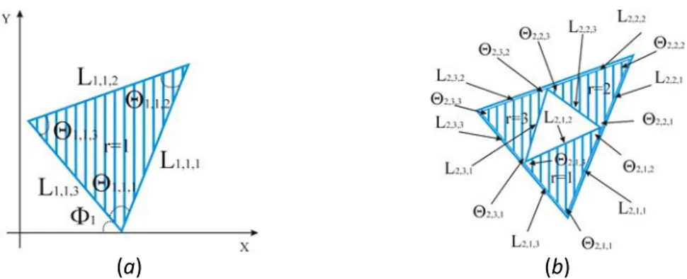
resolution (or fractal stage/iteration). According to the notation used in [1], the template pre‐fractal geometry, whose geometry and descriptive parameters are shown in Fig. 1, is generated by repeatedly applying the so‐called Hutchinson operator on a
Sierpinski‐like reference shape [2]. The antenna structure at the i− fractal stage is th
uniquely determined by: (a) the angle Φ [Fig. 1(a)], (b) a set of segments 1 ,
, , in lengths; (c) a set of angles k j i L, , I i=1,..., j=1,...,J k=1,...,K Θi,j,k, j ( ) being the index of the triangular shape at the 1 3− = i J th j− i− stage and (th ) denotes the segment or angle belonging to the
k
K =3 th k− j− triangular shape. th(a) (b)
Figure 1. Descriptive parameters of the perturbed Sierpinski‐like pre‐fractal antenna:
(a)
i
=
1
and (b)i
=
2
.
In order to satisfy the project guidelines, the values of the descriptive parameters are determined by minimizing the following cost function
( )
γ
=
min[
ϕ
(
γ
)]
Ω
(1) where( )
(
(
) (
)
)
( )
( )
( )
∑
∑∑∑
− = − = − = − = ⎪⎭ ⎪ ⎬ ⎫ ⎪⎩ ⎪ ⎨ ⎧ ⎥ ⎦ ⎤ ⎢ ⎣ ⎡ Δ Δ − Δ Ψ + ⎪⎭ ⎪ ⎬ ⎫ ⎪⎩ ⎪ ⎨ ⎧ ⎥ ⎦ ⎤ ⎢ ⎣ ⎡ Δ Δ Δ Δ Δ Δ Γ − Δ Δ Δ = 1 0 max max 1 0 1 0 1 0 min min , 0 max , , , , , , , 0 max V v M m N n T t f v VSWR f v VSWR f v f m n t G f m n t f m n t G φ θ φ θ φ θ γ ϕ (2) where γ ={
Φ1,Li,j,k,Θi,j,k;i=1,...,I;j=1,...,J;k =1,...,K}
, Γ( )
γ =Γ(
tΔθ,nΔφ,mΔf)
isthe gain evaluated at θ=tΔθf , φ= nΔφ, f =mΔf and Ψ
( )
γ =Ψ( )
vΔf is the value of the VSWR computed at f =mΔf. Moreover, fΔ is the sampling frequency step, Δ θ and Δ are the angular steps in elevation and azimuth direction. φ
Numerical and experimental results
With reference to the synthesis of a L1‐GPS and Wi−Fi dual‐band antenna, the following constraints has been imposed: (i) VSWR≤ VSWRmax =2.0; (ii) gain values greater than Gmin =3.0dBi at θ= 0° and greater than Gmin =−4.0dBi at θ= 70° in the
1
L ‐GPS band by taking into account the presence of a 20 preamplifier stage; (iii) an hemispherical coverage in the
dB Fi
Wi− band. Concerning its physical dimension, the antenna is required to belong to a square physical platform (λL1/4×λL1/4) (iv).
In order to synthesize such a dual‐band antenna, a two‐order (I=2) pre‐fractal shape has been adopted and tuned by minimizing the cost function in (1) with a suitable implementation [5] of the Particle Swarm Optimizer (PSO) [6] integrated with a Method‐of‐Moments (MoM) electromagnetic simulator for carefully modeling the presence of the dielectric slab and of a reference ground plane. The design shown in Fig. 2(a), with dimensions equal to 28 mm along the y‐axis and 32 mm along the x‐axis, has been synthesized.
(a) (b) Figure 2. Dual‐band Sierpinski‐like pre‐fractal antenna: (a) geometry of the synthesized antenna and (b) antenna prototype.
The optimization required Kconv =250 iterations and an amount of CPU‐time of about 10 sec at each iteration (Pentium IV 1800 MHz, 512 MB RAM).
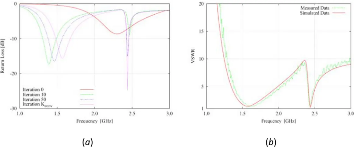
Figure 3(a) shows the evolution of the plot of the Return Loss during the iterative optimization process. Moreover, simulated and experimentally‐measured values (in the presence of a metallic ground plane of dimension ) of the VSWR at the input port of the antenna are compared in Fig. 3(b). As it can be noticed, there is a good agreement between simulated data and measurements (GPS‐ band: vs. ; band: 2 140 90× cm 1 L VSWRsim =1.39 dB
VSWRmeas =1.59 Wi−Fi VSWRsim =1.22 vs. VSWRmeas =1.45).
(a) (b)
Figure 3. Dual‐band Sierpinski‐like pre‐fractal antenna: (a) simulated values of the
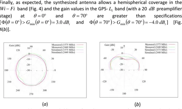
Finally, as expected, the synthesized antenna allows a hemispherical coverage in the band (Fig. 4) and the gain values in the GPS‐ band (with a 20 preamplifier stage) at
Fi
Wi− L1 dB
° = 0
θ and θ= 70° are greater than specifications [Φ
(
θ =0°)
>Gmin(
θ =0°)
=3.0dBi and Φ(
θ =70°)
>Gmin(
θ =70°)
=−4.0dBi] [Fig.4(b)].
(a)
(b)
Figure 4. Dual‐band Sierpinski‐like pre‐fractal antenna. Gain function ‐ Simulated and
measured values: (a) horizontal plane and (b) vertical plane (
φ
= 0°).
Conclusions
A procedure for the design and optimization of non‐harmonic multi‐band pre‐fractal antennas has been described. As a representative example, an antenna structure has been synthesized through the PSO‐based procedure by optimizing the descriptive parameters of a “perturbed” Sierpinski‐like pre‐fractal geometry in order to comply with the requirements in the L1‐GPS and Wi−Fi frequency bands. A set of comparisons between simulated data and measurements has been carried in order to verify the reliability and efficiency of the optimized prototype as well as for drawing a preliminary assessment of the non‐harmonic multi‐band synthesis procedure.
Acknowledgment
This work was partially supported in Italy by Study and Development of Innovative SmartSystems for Highly Reconfigurable Mobile Networks, Progetto di Ricerca di Interesse
Nazionale ‐ Miur Project COFIN 2005099984 and by ARSLOGICA‐CEMIA, DIT‐PRJ‐06‐090 ‐ Industrial Research Project with Arslogica S.r.L.
References:
[1] D. H. Werner, P. L. Werner, and K. H. Church, “Genetically engineered multiband fractal antennas," Electron. Lett., vol. 37, pp. 1150‐1151, Sep. 2001.
[2] D. H. Werner and R. Mittra, Frontiers in electromagnetics. Piscataway: IEEE Press, 2000.
[3] J. Gianvittorio and Y. Rahmat‐Samii, "Fractals antennas: A novel antenna miniaturization technique, and applications," IEEE Antennas Propagat. Mag., vol. 44, pp. 20‐36, Feb. 2002.
[4] C. P. Baliarda, J. Romeu, and A. Cardama, "The Koch monopole: a small fractal antenna," IEEE Antennas Propagat. Mag., vol. 48, pp. 1773‐1781, Nov. 2000.
[5] J. Robinson and Y. Rahmat‐Samii, "Particle swarm optimization in electromagnetics,"
IEEE Trans. Antennas Propagat., vol. 52, pp. 397‐407, Feb. 2004.
[6]