Scuola Dottorale di Ingegneria
Sezione di Ingegneria dell’Elettronica Biomedica, dell’Elettromagnetismo e delle Telecomunicazioni
Design and Implementation of
Metamaterial-Inspired Transmissive and Radiating Microwave
Components
Progetto e Realizzazione di Componenti Trasmissivi e Radiativi a Microonde Ispirati ai Metamateriali
Mirko Barbuto
(XXVI Ciclo della formazione Dottorale)
Abstract
In this thesis, we present the design and the implementation of several metamaterial-inspired transmissive and radiating microwave components, which can be easily integrated in practically realizable systems.
First, we analyze the use of non-Foster active circuits to obtain a widening of the operating bandwidth of devices based on metamaterials (MTMs). In particular, the more suitable loading circuit is analytically determined and it is used to dramatically increase the operating bandwidth of an electrically small antenna consisting of a monopole loaded with a single split-ring resonator (SRR). The non-Foster circuit is designed by using only real components and the stability of the entire system is properly evaluated.
Then, we present some radiating elements based on the use of MTM-inspired resonant inclusions. As a first example, we propose a multi-functional antenna consisting of a printed monopole and two SRRs. Next, we design a compact antenna for Wi-Fi application consisting of two orthogonal parasitic meandered monopoles and a driven bow-tie.
Third, we propose a new class of horn antennas with integrated MTM-inspired filtering modules. In particular, we present some horn antennas that, depending on the used resonant inclusion, show a band-pass or band-stop filtering behavior.
Afterward, we focus our attention on non-radiative elements. In particular, by using complementary electrically small resonators, we design some compact microwave components (i.e. waveguide transition, power dividers, orthomode transducer) that, at the same time, show also a band-pass filtering behavior. Moreover, we design a novel and low-cost MTM-inspired absorber operating in X-band.
Finally, we explore the possibility to generate an electromagnetic field with a non-zero orbital angular momentum (OAM) using a single patch antenna. In particular, we report an analytical study of a circular patch antenna in order to show that a circular polarized TMnm mode generates an OAM of order n-1. Then, we design an elliptical patch antenna that radiates a circular polarized electromagnetic field with OAM of the first order.
Acknowledgements
The completion of my dissertation has been a long journey in which many people have scientifically and humanly contributed. In the next few lines, I will try to thank all the people who supported me, without whose help I could not have made this journey.
I want to express my deeply-felt thanks to my supervisor, Prof. Alessandro Toscano, Head of the Electromagnetic Diagnostic Laboratory, for his warm encouragement and thoughtful guidance during my research activities. I sincerely thank also Prof. Filiberto Bilotti, Head of the Antennas & Special Materials Research Laboratory, who, starting from my B.S. degree, has always tried to bring me on the frontier of metamaterials science. They deserve my heartfelt gratitude for giving me the opportunity to enter the world of higher education and research, and for their valuable advice, constructive criticism and extensive discussions around my work.
My gratitude is also extended to all members of the Department of Engineering at “Roma Tre” University, for the excellent and pleasant working environment. I express my special thanks to my friends and colleagues Dr. Claudia Guattari, Dr. Alessio Monti and Dr. Davide Ramaccia, with whom I have enjoyed many useful and entertaining moments.
I would like to thank Elettronica S.p.A for the use of their near-field measurement system and for support in measurements. I am especially grateful to Dr. Fabrizio Trotta for useful discussions and for his contribution to the realization and characterization of some prototypes.
Last but not least, I want to reserve a special word of gratitude to my family, girlfriend Laura, friends and my fabulous nephews: Alessio, Ginevra, Valerio e Veronica, who have brought great joy to my life. They deserve thanks for their love and a huge variety of other reasons.
Mirko Barbuto “Roma Tre” University April 2015
Table of Contents
ESTESO SOMMARIO ... 1
INTRODUCTION ... 11
NON-FOSTER ACTIVELY LOADED SRR AND APPLICATION IN METAMATERIAL-INSPIRED COMPONENTS ... 21
1.1 ANALYTICAL DETERMINATION OF THE IDEAL LOAD ... 23
1.2 BROADBAND ACTIVE SRR:DESIGN PRINCIPLES ... 25
1.3 BROADBAND SRR-BASED MONOPOLE ANTENNA ... 29
1.4 IMPLEMENTATION ISSUES ... 31
1.5 STABILITY ISSUES... 37
1.6 SUMMARY ... 42
1.7 REFERENCES... 42
COMPACT AND MULTI-FUNCTIONAL ANTENNAS BASED ON MTM-INSPIRED STRUCTURES ... 45
2.1 MULTI-FUNCTIONAL SRR-LOADED PRINTED MONOPOLE ANTENNA... 46
2.1.1 Introduction ... 46
2.1.2 Design of the Proposed Structure ... 47
2.1.3 Numerical Results ... 50
2.2 DESIGN OF A COMPACT ANTENNA BY USING ORTHOGONAL PARASITIC MEANDERED MONOPOLES ... 55
2.2.1 Introduction ... 55
2.2.2 Antenna Design with Equal Meandered Monopoles ... 56
2.2.3 Antenna Design with Slightly Different Meandered Monopoles ... 59
2.3 SUMMARY ... 63
2.4 REFERENCES... 64
HORN ANTENNAS WITH INTEGRATED MTM-INSPIRED FILTERING MODULES ... 67
3.1 LINEAR-TO-CIRCULAR POLARIZATION TRANSFORMER ... 68
3.1.1 Design of the Linear-To-Circular Polarization Transformer ... 69
3.1.2 Design of the Self-Filtering Circularly Polarized Horn Antenna ... 74
3.2 ACOMBINED BANDPASS FILTER AND POLARIZATION TRANSFORMER FOR HORN ANTENNAS 78 3.2.1 Design of a planar Linear-To-Circular Polarization Transformer ... 78
II Table of Contents
3.2.2 Design of the Self-Filtering Circularly Polarized Horn Antenna ... 82
3.2.3 Experimental Realization and Measurements ... 85
3.3 HORN ANTENNAS WITH INTEGRATED NOTCH FILTERS ... 86
3.3.1 Design of a Horn Filtenna with a Single-Band-Stop Characteristic ... 87
3.3.2 Design of a Horn Filtenna with a Dual-Band-Stop Characteristic ... 92
3.3.3 Experimental Realization and Measurements ... 94
3.4 SUMMARY ... 96
3.5 REFERENCES ... 98
NOVEL MTM-INSPIRED MICROWAVE COMPONENTS... 100
4.1 NOVEL WAVEGUIDE COMPONENTS BASED ON COMPLEMENTARY ELECTRICALLY SMALL RESONATORS ... 101
4.1.1 Design of a Rectangular-To-Circular Waveguide Transition ... 102
4.1.2 Design of Power Dividers ... 106
4.1.3 Design of an Orthomode Transducer ... 109
4.2 LOW-COST AND BROADBAND MTM-INSPIRED ABSORBER WITHOUT A METALLIC BACKING 111 4.2.1 Design of the Metasurface ... 112
4.2.2 Design of the Resistive Sheet... 113
4.2.3 Implementation of the Absorber ... 118
4.2.4 Experimental Realization and Measurements ... 119
4.3 SUMMARY ... 121
4.4 REFERENCES ... 122
CIRCULAR POLARIZED PATCH ANTENNA GENERATING ORBITAL ANGULAR MOMENTUM ... 125
5.1 ANALYTICAL STUDY ... 126
5.2 VALIDATION THROUGH FULL-WAVE NUMERICAL SIMULATIONS ... 131
5.3 EXPERIMENTAL REALIZATION AND MEASUREMENTS ... 134
5.4 SUMMARY ... 135
5.5 REFERENCES ... 136
PUBLICATIONS ... 138
List of Figures
Fig. 1: (a) Geometry of a SRR loaded with an arbitrary impedance ZL and (b) its lumped element equivalent circuit representation. ... 24
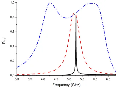
Fig. 2: Magnitude of the S11 parameter of the unloaded SRR case (solid line), of the SRR loaded with a LC tank circuit (dashed line), and of the SRR loaded with a LC tank circuit in series with an inductance (dot-dashed line). ... 26
Fig. 3: Magnitude of the S11 parameter of a waveguide with a SRR loaded with different test capacitances (values in the range -0.05-0.05 pF). ... 27
Fig. 4: Reactance of the loading capacitance as a function of the corresponding resonant frequency (triangular symbols), reactance of the LC tank non-Foster circuit (values in (5) have been used) (dashed line), and non-Foster reactance of a LC tank circuit in series with an inductor (values in (5) have been used) (solid line). ... 28
Fig. 5: Geometrical sketch of the SRR-based antenna proposed in [23]. Antenna dimensions in cm: h = 3.00, h1 = 31.60, h2 = 29.64, d1 = 1.14, d2 = 1.90. SRR
dimensions in cm: w = 3.42, R = 13.70, g = 0.76, s = 0.76. Slab (FR-4): r
ε = 3.5, tanδ = 0.025 , thickness: 6.08 mm. ... 30 Fig. 6: Magnitude of the S11 parameter of the unloaded (dashed line) and loaded (solid line) antenna. ... 30
Fig. 7: SRR-based monopole antenna loaded with a parallel connection of two NIC circuits. ... 33
Fig. 8: Magnitude of the S11 parameter of the unloaded (solid line), ideally loaded (dashed line), NIC loaded (dotted line), and real NIC loaded (dot-dashed line) antenna. ... 34 Fig. 9: Input impedance of the unloaded and real NIC loaded antennas in real (solid and dotted line, respectively) and imaginary (dashed and dot-dashed line, respectively) part. ... 36
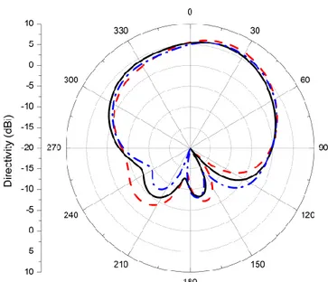
Fig. 10: Directivity patterns of the real NIC loaded antenna in the E-plane at 100 MHz (solid line), 96.1 MHz (dashed line) and 106.1 MHz (dot-dashed line). ... 36
IV List of Figures
Fig. 11: Directivity patterns of the real NIC loaded antenna in the H-plane at 100 MHz (solid line), 96.1 MHz (dashed line) and 106.1 MHz (dot-dashed line). ... 37
Fig. 12: Equivalent model of the ideally loaded SRR. ... 38 Fig. 13: Time-domain behavior of the current for the case of the unloaded antenna (thick black line) and for the case of an ideal 50 Ohm load (thin red line). ... 41
Fig. 14: Time-domain behavior of the current for the case of the loaded antenna (thick black line) and for the case of an ideal 50 Ohm load (thin red line). ... 41
Fig. 15: Geometrical sketch of the single-SRR loaded printed monopole. Antenna dimensions are in mm: Wg = 30, Lg = 15, Lm = 12, Wm = 5, LSRR = 10, g = 0.2, s = 0.2. Slab material: FR-4 (εr = 4.4, tan δ = 0.0085). Slab thickness: 1.59 mm. Separation between monopole and SRR: 0.2 mm... 47
Fig. 16: Magnitude of the scattering parameter S11 of the antenna reported in Fig. 1 and of a standard printed monopole antenna with the same dimensions. ... 48
Fig. 17: 3D directivity pattern of the single-SRR loaded printed monopole at the resonant frequency of the SRR 1.752 GHz. ... 49
Fig. 18: Geometrical sketch of the multi-functional two-SRR loaded printed monopole. The numbered markers represent the switches placed in the gaps. ... 50
Fig. 19: Magnitude of the S11 parameter of the two-SRR loaded printed monopole for the eight switch status reported in Table I. ... 51
Fig. 20: Perspective view of the proposed antenna. The ground side is 10 cm. ... 56 Fig. 21: Front view (a) and back view (b) of the proposed antenna with equal meandered monopoles. Antenna dimensions are: RBT = 4.9 mm, Hm = 4.5 mm, gm = 0.3 mm, wm = 0.48 mm, L = 3 mm. ... 57
Fig. 22: Reflection coefficient amplitude of the proposed antenna with equal meandered monopoles. ... 58
Fig. 23: Realized gain pattern at the resonant frequency (2.425 GHz) of the antenna with equal meandered monopoles. ... 58
Fig. 24: Surface currents on the two meandered monopoles at the resonant frequency of the overall structure (2.425 GHz). ... 59
Fig. 25: Front view (a) and back view (b) of the proposed antenna with slightly different meandered monopoles. Antenna dimensions are: RBT = 5 mm, Hm = 4.5 mm, gm = 0.3 mm, wm = 0.48 mm, L = 3 mm. ... 60
Fig. 26: Reflection coefficient amplitude of the proposed antenna with slightly different monopoles (red-solid line), compared to the one of the previous case (black-dashed line). ... 61 Fig. 27: Surface currents on the two meandered monopoles at the lowest resonant frequency of the overall structure shown in Fig. 6. ... 61
Fig. 28: Surface currents on the two meandered monopoles at the highest resonant frequency of the overall structure shown in Fig. 6. ... 62
Fig. 29: Realized gain pattern at the lowest resonant frequency (2.416 GHz) of the antenna with slightly different monopoles. ... 62
Fig. 30: Realized gain pattern at the highest resonant frequency (2.461 GHz) of the antenna with slightly different monopoles. ... 63
Fig. 31: 3D view of the novel resonator (left) and of the proposed polarization transformer where we can see the two driven monopoles connected across an electrically small aperture made in a metallic screen (right). ... 70
Fig. 32: Geometrical sketch of the proposed polarization transformer and its integration with a linearly polarized rectangular waveguide. ... 71
Fig. 33: Dimensions of the electrically small resonator used to design the polarization transformer: R1_CLL1 = R1_CLL2 = 15 mm, R2_CLL1 = 11.73 mm, R2_CLL2 = 12.21 mm, H1_CLL1 = 13.04 mm, H1_CLL2= 13.5 mm, H2_CLL1 = 13.9 mm, H2_CLL2 = 14 mm, W_CLL1 = W_CLL2 = 1.4 mm, G1 = 0.3 mm, G2 = 0.2 mm, G3 = 2 mm. Metallizations are printed on the two sides of an 0.7874 mm thick Rogers Duroid 5880 dielectric slab. ... 72
Fig. 34: Reflection coefficient of an open ended rectangular waveguide (dash-dotted line), of the same waveguide with a sub-wavelength circular aperture (dashed line), and of the structure shown in Fig. 2. ... 72
Fig. 35: Realized gain radiation patterns at 1.575 GHz of the structure shown in Fig. 2 (φ = 0°). ... 73
VI List of Figures
Fig. 36: Realized gain radiation patterns at 1.575 GHz of the structure shown in Fig. 2 (φ = 90°). ... 73
Fig. 37: Axial ratio for the main beam direction of the structure shown in Fig. 2. ... 74 Fig. 38: Top view (left) and perspective view (right) of the self-filtering circularly polarized horn antenna. ... 75
Fig. 39: Reflection coefficient of the self-filtering circularly polarized horn antenna shown in Fig. 8. ... 76
Fig. 40: Axial ratio for the main beam direction of the self-filtering circularly polarized horn antenna shown in Fig. 8. ... 77
Fig. 41: Realized gain radiation patterns at 1.575 GHz of the self-filtering circularly polarized horn antenna shown in Fig. 8 (φ = 0°). ... 77
Fig. 42: Realized gain radiation patterns at 1.575 GHz of the self-filtering circularly polarized horn antenna shown in Fig. 8 (φ = 90°). ... 78
Fig. 43: Geometrical sketch of the proposed polarization transformer with dimensions: L = 5.8 mm, La1 = 0.3 mm, La2 = 0.9 mm, Lm = 0.8 mm, Wd = 0.4 mm, Wa = 0.4 mm. 79
Fig. 44: Geometrical sketch of the proposed polarization transformer and its integration with a linearly polarized rectangular waveguide. ... 80
Fig. 45: Reflection coefficient amplitude of an open ended rectangular waveguide (dashed line) and of the structure shown in Fig. 2 (solid line). ... 80
Fig. 46: Realized gain patterns at 15.75 GHz of the structure shown in Fig. 2: (left) φ = 0°; (right) φ = 90°. ... 81
Fig. 47: Axial ratio for the main beam direction of the structure shown in Fig. 2. ... 81 Fig. 48: Side view (left) and perspective view (right) of the filtering circularly polarized horn antenna. Corrugated horn dimensions: Ds = 6.3 mm, Lg = 33 mm, Lh = 25.6 mm, Lt = 5 mm, Ws = 1.3 mm, Wr = 1.3 mm. ... 82
Fig. 49: Simulated and measured reflection coefficient amplitude of the self-filtering circularly polarized horn antenna shown in Fig. 6. ... 83
Fig. 50: Simulated and measured axial ratio for the main beam direction of the self-filtering circularly polarized horn antenna shown in Fig. 6. ... 84
Fig. 51: Simulated and measured realized gain patterns at 15.85 GHz of the self-filtering circularly polarized horn antenna shown in Fig. 6: (left) φ = 0°; (right) φ = 90°. ... 84 Fig. 52: Realized gain (solid line) and directivity (dashed line) of the self-filtering circularly polarized horn antenna shown in Fig. 6. ... 85
Fig. 53: Photographs showing: (a) side view of the overall antenna structure consisting of a coaxial-to-waveguide transition, the proposed polarization transformer, and a corrugated conical horn; (b) front view of the overall antenna structure; (c) the realized polarization transformer; (d) the overall antenna structure in the Satimo StarLab. ... 86
Fig. 54: Geometrical sketch of the proposed horn antenna with the notched-band filter: (a) perspective view; (b) front view; (c) side view. ... 88
Fig. 55: Reflection coefficient amplitude at the input port of the structure shown in Fig. 1 for different positions of the SRR. ... 89
Fig. 56: Measured and simulated reflection coefficient amplitude at the input port of the structure shown in Fig. 1 for the case of d = 15 mm. ... 89
Fig. 57: Measured and simulated realized gain in the main beam direction of the proposed horn antenna with the notched-band filter and of the corresponding standard horn antenna. ... 90
Fig. 58: Close-up of the measured and simulated realized gain in the main beam direction of the proposed horn antenna with the notched-band filter and of the corresponding standard horn antenna. ... 90
Fig. 59: Simulated and measured realized gain patterns of the proposed horn antenna with and without the notched-band filter on the E-plane (left column) and H-plane (right column) at: (a) 9 GHz, (b) 10 GHz and (c) 11 GHz. ... 91
Fig. 60: Geometrical sketch of the proposed horn antenna with the dual-band-notch filter: (a) perspective view; (b) front view; (c) side view. ... 92
Fig. 61: Simulated and measured reflection coefficient amplitude at the input port of the horn filtenna with a dual band-stop characteristic. ... 93
VIII List of Figures
Fig. 62: Simulated realized gain in the main beam direction of the horn antenna with and without a dual-band-stop filter. ... 93
Fig. 63: Close-up of the simulated realized gain in the main beam direction of the horn antenna with and without a dual-band-stop filter. ... 94
Fig. 64: Photographs showing: top (a) and bottom (b) views of the realized filtering module; (c) the filtering module fixed in the horn antenna; (d) perspective view of the proposed self-filtering horn antenna; (e) the proposed structure placed inside the near-filed measurement system. ... 95 Fig. 65: Photographs showing the transmission measurement setup. ... 96 Fig. 66: Power transmission between two single-band filtering horn antennas, two standard horns and between a standard horn and the single-band filtering horn antenna, in the setup shown in Fig. 11. ... 96
Fig. 67: Geometrical sketch of the proposed complementary resonator with dimensions: L = 8.2 mm, La1 = 2 mm, La2 = 1.9 mm, Hm1 = 1.8 mm, Hm2 = 1.5 mm, Wd = 0.4 mm, Wa = 0.4 mm. The resonator is drilled in a metallic sheet. ... 103 Fig. 68: Geometrical sketch of the proposed rectangular-to-circular waveguide transition. ... 103
Fig. 69: Electric field lines at the waveguide ports of the structure shown in Fig. 2: (a) TE10-mode of the rectangular waveguide, (b) and (c) degenerate TE11-modes of the circular waveguide. ... 104
Fig. 70: Simulated magnitude of the scattering parameters of the structure shown in Fig. 2. ... 105
Fig. 71: Simulated phase difference between the degenerate TE11-modes at port 2 of the structure shown in Fig. 2. ... 105
Fig. 72: Rigth view (a), left view (b), perspective view (c) and top view (d) of the power divider having output ports in circular waveguides. ... 106
Fig. 73: Simulated magnitude of the scattering parameters of the structure shown in Fig. 6. ... 107
Fig. 74: Simulated phase difference between the degenerate TE11-modes at port 2 (black-solid line) and port 3 (red-dashed line) of the structure shown in Fig. 6. ... 107
Fig. 75: Rigth view (a), left view (b), perspective view (c) and top view (d) of the power divider with output ports in rectangular waveguides. Complementary resonator dimensions are: L = 8.2 mm, La1 = 2 mm, La2 = 2 mm, Hm1 = 1.5 mm, Hm2 = 1.5 mm, Wd = 0.4 mm, Wa = 0.4 mm. ... 108
Fig. 76: Simulated magnitude of the scattering parameters of the structure shown in Fig. 9. ... 108
Fig. 77: Perspective view of the proposed orthomode transducer. ... 109 Fig. 78: Geometrical sketch of the linearly polarized complementary resonator with dimensions: L = 8.6 mm, La = 3.5 mm, Hm = 2 mm, Wd = 0.4 mm, Wa = 0.4 mm. ... 110
Fig. 79: Simulated magnitude of the scattering parameters of the structure shown in Fig. 11. ... 110
Fig. 80: Geometrical sketch describing the structure of a traditional Salisbury screen. ... 112 Fig. 81: Simulated amplitude of the transmission and reflection coefficients (for normal incidence) of the proposed metasurface (inset: geometrical sketch of the metasurface and dimensions of the metallic rings). ... 113
Fig. 82: (a) Commercial graphite powder spray produced by ATAL SrL; (b) A realized resistive sheet composed by a plastic sheet covered by a proper amount of graphite powder. The two images are not in scale. ... 115
Fig. 83: Application of the Van der Pauw method for the resistive sheet characterization. ... 115
Fig. 84: Surface resistance exhibited by the 18 realized samples compared to the relative graphite powder surface density. ... 117
Fig. 85: Experimental setup used to measure the reflection coefficient of the realized resistive sheets. In the inset it is shown a properly shaped resistive sheet supported by a sample holder. ... 118
X List of Figures
Fig. 86: Comparison between the measured and the simulated amplitude of the S11 parameter for two resistive sheets with 41 / sqand 141 / sq, respectively. ... 118
Fig. 87: (a) Geometrical sketch, (b) rear view and (c) front view of the proposed metamaterial-inspired absorber. ... 119
Fig. 88: Photograph of the measurement system consisting of two high-gain pyramidal horn antenna and the sample holder... 120
Fig. 89: Absorption of the metamaterial-inspired absorber shown in Fig. 3. ... 120 Fig. 90: Geometrical sketch of a circular patch antenna. The main geometrical parameters are the radius of the patch a and the thickness of the dielectric substrate h. ... 127 Fig. 91: Ratio between the amplitude of the terms A and B in the case of a circular patch antenna working in a CP TM21 mode for different values of substrate permittivity. ... 129 Fig. 92: Phase patterns (in degree) of the x (left) and y (right) component of the radiated electric field in the case of: (a) RHCP TM11 mode; (b) RHCP TM21 mode; (c) RHCP TM31 mode... 130
Fig. 93: Top view of the elliptical patch antenna. The inner conductor of the coaxial cable is connected to the point p (x = 8.75 mm; y = 21 mm). The origin of the reference system is at the shape centre. Antenna dimensions are: A1 = 75,2 mm, A2 = 81.6 mm, and L = 100 mm. ... 131
Fig. 94: Simulated (red-solid line) and measured (black-dashed line) reflection coefficient amplitude of the proposed elliptical patch antenna shown in Fig. 4... 132
Fig. 95: Phase patterns at 2.4 GHz of the x (left) and y (right) component of the radiated electric field by the elliptical patch antenna, shown in Fig. 4, working in a RHCP TM21 mode... 133
Fig. 96: Simulated Azimuth (left) and Elevation (right) radiation phase patterns at 2.4 GHz of the elliptical patch antenna, shown in Fig. 4, working in a RHCP TM21 mode. ... 133
Fig. 97: 3-D directivity pattern at 2.4 GHz of the elliptical patch antenna, shown in Fig. 4, working in a RHCP TM21 mode. ... 133
Fig. 98: Photograph showing the realized elliptical patch antenna with the dimensions given in Fig. 4. ... 134
Fig. 99: Measured Azimuth (left) and Elevation (right) radiation phase patterns at 2.4 GHz of the prototype shown in Fig. 9. ... 135
XII List of Tables
List of Tables
Table 1: Nominal values of the real lumped elements of the circuit shown in Fig. 8. 35 Table 2: Summary of the operation frequencies and radiation properties for the different combinations of the switch status. ... 52
Esteso Sommario
(Italiano)
l termime “metamateriale” (MTM) fa riferimento ad un ampio insieme di materiali artificiali, tipicamente sintetizzati inserendo delle opportunamente strutture metalliche di particolare forma e dimensione all’interno di un mezzo dielettrico ospitante [1]-[4]. I parametri geometrici ed elettromagnetici di tali inclusioni sono progettati per alterare la risposta del materiale ospitante ed ottenere proprietà anomale non riscontrabili nei materiali convenzionali alle frequenze di interesse. Soltanto per citare un esempio, sebbene alcuni materiali naturali (e.g. metalli nobili e alcuni semiconduttori) mostrano valori anomali (i.e. negativi o nulli) della permittività elettrica alle frequenze dell’infrarosso, visibili e ultraviolette [5]-[6], non sono noti materiali naturali con caratteristiche simili alle frequenze delle microonde. Allo stesso modo, le proprietà magnetiche dei materiali naturali sono limitate alle frequenze radio ed alle basse microonde [7] e, di conseguenza, valori anomali di permeabilità magnetica non sono naturalmente disponibili nel dominio visibile, infrarosso e ultravioletto. Tuttavia, quando la natura non ci fornisce i valori necessari dei parametri elettromagnetici, i MTM possono essere utilizzati con successo per ottenere i valori anomali desiderati.
Ad esempio, come anticipato teoricamente in [8] e dimostrato sperimentalmente in [9], è possible ottenere un MTM caratterizzato da un indice di rafrazione negativo alle frequenze delle microonde combinando opportunamente sottili fili metallici [10] e split-ring resonator (SRR). Infatti, poichè in tale materiale le inclusioni e la distanza tra di esse sono inferiori rispetto alla lunghezza d’onda operativa, è possibile introdurre valori efficaci di permettività, permeabilità e indice di rifrazione, i quali possono assumere valori anomali. La loro sintesi prende spunto dall’idea introdotta da Pendry [9], secondo la quale una serie di dipoli elettrici orientati causa un comportamento risonante della permittività elettrica efficace del mezzo. In modo simile, un insieme di dipoli magnetici genera un’analoga risonanza della permeabilità magnetica efficace associata al MTM. Se le due risonanze si verificano nello stesso intervallo di frequenze, siamo in grado di
I
2 Esteso Sommario
sintetizzare un materiale con un indice di rifrazione negativo in un determinato intervallo di frequenze.
L’elemento fondamentale per la realizzazione del primo MTM è stato quindi lo SRR, il quale è un risonatore miniaturizzato utile per ottenere il magnetismo artificiale alle frequenze delle microonde. Un singolo SRR è costituito da due anelli aperti concentrici di materiale metallico, le cui aperture sono poste a lati opposti della struttura. Tale configurazione permette di aumentare la capacità totale del risonatore rispetto a quella di una struttura a singolo anello, aggiungendo una capacità distribuita tra i due anelli concentrici. In questo modo, la frequenza di risonannza del risonatore può essere significativamente ridotta per raggiungere una dimensione elettrica dell’ordine di λ/10. Dopo quanto proposto in [9], sono state introdotte molte inclusioni magnetiche differenti per ottenere un maggiore grado di miniaturizzazione, rimuovere la bi-anisotropia intrinseca che caratterizza il comportamento di uno SRR [11]-[14], e ottenere una risposta isotropa [15]-[18].
Accanto a questi sforzi modellistici, sono state investigate molte proprietà innovative dei MTM. In particolare, l’effetto di super-risoluzione di un MTM con indice di rifrazione negativo ha mostrato come sia possibile superare il limite fisico della diffrazione. Una lente convenzionale, infatti, è in grado di focalizzare un dettaglio con un limite ben noto in ottica: fissata la frequenza operativa, tale dettaglio non può essere inferiore alla corrispondente lunghezza d’onda di lavoro. Una lamina opportunamente progettata di MTM può invece andare idealmente al di sotto del limite fisico della diffrazione, focalizzando dettagli con dimensioni inferiori alla lunghezza d’onda. Altre applicazioni interessanti dei MTM derivano dall’idea che, se utilizziamo insieme una coppia di materiali artificiali coniugati, possiamo progettare cavità risonanti di dimensioni trasversali molto inferiori alla lunghezza d’onda. A partire da questa idea di base, sono stati proposti numerosi componenti e dispositivi innovativi basati sulle propietà dei MTM, come ad esempio super-lenti [19]-[20], iper-lenti [21], rivestimenti per l’invisibilità elettromagentica [22]-[24], componenti radianti compatti [25]-[29], dispositivi per l’aumento della trasmissione da foro elettricamente piccolo [30]-[36], filtri [37], assorbitori [38], ecc. Inoltre, negli ultimi anni, sfruttando le potenzialità offerte dalla nano-fabricazione, il range operativo in frequenza dei MTM è stato esteso
fino alle frequenze ottiche [39]-[43]. In questo caso, tuttavia, i risonatori magnetici usati alle microonde non possono essere facilmente impiegati [44] e, di conseguenza, sono stati introdotti design alternativi con un minore grado di miniaturizzazione [45]-[46], o basati su approcci concettualmente differenti [47]-[48].
Tuttavia, qualunque sia la gamma di frequenze di interesse, i materiali magnetici artificiali o più in generale i MTM presentano alcune limitazioni intrinseche. A causa di considerazioni energetiche, infatti, ogni MTM passivo deve essere necessariamente un mezzo dispersivo [49]. I valori desiderati dei parametri elettromagnetici sono quindi ottenuti soltanto in un ristretto intervallo di frequenze e, di conseguenza, la banda operativa dei componenti basati su MTM è tipicamente a sua volta limitata. Inoltre, come risulta chiaro dalle relazioni di causalità di Kramers-Kronig, il fenomeno di dispersione è sempre legato a meccanismi di perdita [49], i quali riducono ulteriormente le potenzialità dei MTM.
Il Capitolo 1 di questa tesi è, quindi, dedicato all’impiego di elementi attivi di tipo non-Foster per aumentare la banda operativa di uno SRR per possibili applicazione nei componenti ispirati ai MTM. Innanzitutto, determineremo la tipologia circuitale del carico attivo richiesta per compensare la reattanza intrinseca dello SRR ed ottenere un comportamento a banda larga. Successivamente, mostreremo che la stessa procedura può essere applicata con successo al caso di un’antenna a monopolo basata su SRR e, in linea di principio, a qualsiasi dispositivo ispirato ai MTM che fa uso di SRR. Infine, integrando un simulatore circuitale ed uno elettromagnetico, proporremo una possibile implementazione realistica del carico attivo, basata sull’impiego di elementi circuitali disponibili in commercio. I risultati ottenuti (ampliamento di sette volte della banda di impedenza dell’antenna in esame) dimostrano che carichi attivi di tipo non-Foster possono essere usati con successo per aumentare la larghezza di banda, altrimenti intrensicamente ridotta, di MTM passivi basati su SRR e dei componenti ispirati ai MTM. Vedremo inoltre che i problemi realizzativi legati alla dispersione degli elementi circuitali, agli effetti parassiti e alla stabilità del circuito attivo possono essere opportunamente tenuti in considerazione in fase di progetto.
Il Capitolo 2 di questa tesi sarà invece dedicato al progetto di nuovi elementi radianti compatti e multifunzione ispirati ai concetti dei MTM. Per prima cosa, presenteremo il
4 Esteso Sommario
progetto di un’antenna a monopolo stampato caricata con due SRR identici. L’idea è quella di utilizzare gli SRR non solo per miniaturizzare le dimensioni dell’antenna ma anche per introdurre risonanze multiple che possono essere opportunamente selezionate utilizzando switch elettronici posti nei quattro gap dei due SRR. Combinando opportunamente gli stati ON/OFF dei quattro switch, infatti, vedremo come sia possibile cambiare la frequenza operativa e/o la forma del diagramma di radiazione dell’antenna a monopolo o aggiungere nuove frequenze operative. Successivamente, presenteremo invece un’antenna compatta costituita da due monopoli a meandro ortogonali che agiscono come elementi parassiti di un bow-tie alimentato. In particolare, mostreremo che utilizzando due monopoli con dimensioni leggermente differenti è possibile ottenere una maggiore larghezza di banda di impedenza. Utilizzando tale approccio, presenteremo un’antenna compatta operante nella banda del Wi-Fi a 2.4 GHz con dimensioni elettriche complessive pari a 0/ 60/120/ 75.
Nel Capitolo 3, focalizzeremo invece la nostra attenzione sul progetto di antenne ad horn con moduli filtranti integrati ispirati ai MTM. A tale scopo, proporremo innanzitutto l’utilizzo di antenne compatte per il progetto di un nuovo setup per l’aumento della trasmissione da foro elettricamente piccolo. Tale setup consiste di un disco metallico circolare con un’apertura attraverso la quale sono poste due coppie di antenne elettricamente piccole a polarizzazione circolare. Mostreremo inoltre che la struttura proposta, se posta alla fine di una guida d’onda rettangolare aperta, è in grado di cambiare la sua polarizzazione da lineare a circolare. Successivamente, integrando tale trasformatore di polarizzazione in un’antenna ad horn, mostreremo come sia possibile ottenere un’antenna ad horn filtrante a polarizzazione circolare. Tuttavia, tale modulo filtrante non è planare, è costituito da strutture differenti poste ortogonalmente tra loro, richiede l’utilizzo di materiali dielettrici comportando una riduzione di efficienza, e può operare soltanto con segnali di bassa potenza (i.e. può operare soltanto in modalità ricevente). Al fine di superare tali limiti, proporremo quindi un nuovo trasformatore di polarizzazione costituito da un risonatore complementare elettricamente piccolo intagliato su uno schermo metallico. Mostreremo prima che tale componente è in grado di trasformare la polarizzazione lineare di una guida d’onda rettangolare operante nel suo modo fondamentale in una circolare. Successivamente,
integrando tale convertitore di polarizzazione in un horn conico, mostreremo come sia possibile ottenere un’antenna ad horn filtrante in polarizzazione circolare. Il comportamento della struttura proposta sarà validato tramite simulazioni numeriche e misurazioni effettuate su un prototipo.
Si noti, tuttavia, che tale approccio prevede l’inserimento di uno schermo metallico ortogonale alla direzione di propagazione del campo elettromagnetico; di conseguenza, esso può essere utilizzato soltanto per componenti a microonde che debbano mostrare un comportamento di tipo passa-banda. Al fine di progettare antenne ad horn filtranti o componenti a microonde con una carratteristica di tipo notch (elimina banda), dobbiamo quindi rimuovere lo schermo metallico e progettare un’inclusione risonante che sia in grado di immagazzinare/dissipare energia ad una data frequenza, ottenendo così una banda proibita in uno stretto intervallo di frequenze. A tale scopo, presenteremo quindi il progetto di antenne ad horn filtranti con un comportamento elemina banda ottenuto attraverso l’utilizzo di risonatori magnetici elettricamente piccoli. In particolare, uno SRR realizzato su un substrato dielettrico Rogers DuroidTM RT5870 sarà inserito all’interno di un’antenna ad horn ad una opportuna distanza dalla sua apertura. Intorno alla frequenza di risonanza dello SRR la trasmissione sarà quindi fortemente ridotta ottenendo così un comportamento di tipo notch. Al fine di estendere tale risultato al caso di operatività dual-band, proporremo inoltre il progetto di un modulo filtrante costituito da due SRR con dimensioni differenti. Anche in questo caso, la validità dell’approccio proposto sarà verificata attraverso un opportuno set di simulazioni full-wave e esperimenti condotti su prototipi.
Mentre nei primi capitoli saranno presentate diverse tipologie di strutture radianti, nel Capitolo 4 affronteremo il progetto di nuovi componenti a microonde. In particolare, il trasformatore di polarizzazione planare presentato nel Capitolo 3 sarà utilizzato per progettare una nuova classe di componenti in guida d’onda. Innanzitutto, presenteremo una transizione in guida d’onda da rettangolare a circolare che permetta di collegare efficacemente guide d’onda con sezioni trasversali differenti e di trasformare il modo TE10 a polarizzazione lineare della guida d’onda rettangolare in un modo TE11 a polarizzazione circolare della guida d’onda circolare. Successivamente, utilizzando strutture simili, presenteremo il progetto di due divisori di potenza e di un trasduttore di
6 Esteso Sommario
modi ortogonali. Tutti questi componenti, impiegando soltanto sottili fogli metallici opportunamente forati, possono essere integrati nei sistemi standard di trasmissione in guida d’onda senza aumentare la loro occupazione di spazio. Come ulteriore esempio di componenete a microonde ispirato ai concetti dei MTM, mostreremo inoltre un assorbitore innovativo a basso costo operante nella banda X. Esso consiste di un singolo foglio resistivo opportunamente spaziato da una metasuperficie a doppio ring. Il suo principio di funzionamento è simile a quello di uno schermo di Salisbury, nel quale un foglio resistivo a 377 Ω/sq è posto a λ/4 da un piano metallico. Tuttavia, nella nostra configurazione, la metasuperficie sostituirà il supporto metallico riducendo la percentuale di metallo utilizzata. Ciò è molto convenienete quanto l’assorbitore è utilizzato per ridurre la sezione trasversale radar o radar cross section (RCS) di oggeti non metallici. In un simile scenario operativo, l’assenza di un piano metallico permette di ridurre notevolmente il peso della struttura complessiva e di aumentare in maniera minore la RCS dell’oggetto al di fuori della banda operativa dell’assorbitore. Le prestazioni della metasuperficie e dell’assorbitore complessivo saranno valutate attraverso simulazioni full-wave e misurazioni effettuate su un prototipo.
Tutti i componenti suddetti sono ispirati al concetto di MTM e permettono di eseguire diverse operazioni sul segnale elettromagnetico, come un filtraggio di tipo passa-banda o elimina banda o la trasformazione della polarizzazione. Poiché molti di essi sono costituiti da una singola particella ispirata ai MTM, tali componenti possono essere facilmente integrati nell’elemento radiante, eseguendo la manipolazione del segnale direttamente sul campo elettromagnetico trasmesso o ricevuto. Un’altra possibile manipolazione che può essere eseguita su un segnale elettromagnetico è la generazione del momento angolare orbitale (OAM). In particolare, la recente estensione del concetto di OAM dalle frequenze ottiche a quelle delle microonde ha portato alcuni ricercatori ad esplorare come le tecniche radiative a microonde possano essere utilizzate per irradiare un campo elettromagnetico con OAM non nullo. A tal riguardo, il Capitolo 5 mira a presentare un nuovo approccio per generare un campo con OAM non nullo attraverso l’utilizzo di una singola antenna a patch. Utilizzando il modello a cavità, per prima cosa analizzeremo il campo irradiato da un patch circolare standard e mostreremo che un modo TMnm a polarizzazione circolare eccitato mediante due cavi coassiali è in grado di
generare un campo elettromagnetico con OAM di ordine ±(n-1). Successivamente, al fine di ottenere una struttura più semplice con un singolo feed, progetteremo un’antenna a patch ellittico in grado di irradiare un modo TM21 a polarizzazione circolare destra. Utilizzando simulazioni full-wave ed esperimenti su un prototipo fabbricato, mostreremo che l’antenna proposta è in grado di irradiare efficacemente un campo elettromagnetico con un OAM del primo ordine.
References
[1] G.V. Eleftheriades, and K.G. Balmain, Negative Refraction Metamaterials: Fundamental Principles and Applications. Hoboken, NJ: Wiley-IEEE Press, 2005. [2] N. Engheta, and R.W. Ziolkowski, Electromagnetic Metamaterials: Physics and
Engineering Explorations. Hoboken, NJ: Wiley-IEEE Press, 2006.
[3] R. Marqués, F. Martín, M. Sorolla, and F. Capolino, Metamaterials with Negative Parameters: Theory, Design and Microwave Applications. Hoboken, NJ: Wiley-Interscience, 2008.
[4] S. Zouhdi, A. Sihvola, and A. P. Vinogradov, Metamaterials and Plasmonics: Fundamentals, Modelling, Applications. Dordrecht, NL: Springer-Verlag GmbH, 2008.
[5] P.B. Johnson, R. W. Christy, “Optical constants of the noble metals,” Phys. Rev. B, Vol. 6, pp. 4370-4379, 1972.
[6] E.D. Palik, Handbook of Optical Constants of Solids, Boston, NE: Academic Press, 1998.
[7] L.D. Landau, L.P. Pitaevskii, and E.M. Lifshitz, Electrodynamics of Continuous Media, Second Edition: Volume 8. Oxford, EN: Pergamon Press, 1984.
[8] V.G. Veselago, “The electrodynamics of substances with simultaneously negative values of ε and μ,”, Sov. Phys. Uspekhi, Vol. 10, pp. 509–514, 1968.
[9] D.R. Smith, W.J. Padilla, D.C. Vier, S.C. Nemat-Nasser, and S. Schultz, “Composite medium with simultaneously negative permeability and permittivity,” Phys. Rev. Lett., Vol. 84, pp. 4184-4187, 2000.
[10] W. Rotman, “Plasma simulation by artificial dielectrics and parallel-plate media,” IRE Trans. Antennas Propagat., Vol. 10, pp. 82-25, 1962.
[11] R. Marqués, F. Medinaand, and R. Rafii-El-Idrissi, “Role of bi-anisotropy in negative permeability and left handed metamaterials,” Phys. Rev. B, Vol. 65, 144441, 2002.
[12] R. Marqués, F. Mesa, J. Martel, and F. Medina, “Comparative analysis of edge and broadside coupled split ring resonators for metamaterial design. Theory and experiment,” IEEE Trans. Antennas Propagat., Vol. 51, pp. 2572–2581, 2003.
8 Esteso Sommario
[13] R. Marqués, J. D. Baena, J. Martel, F. Medina, F. Falcone, M. Sorolla, and F. Martin, “Novel small resonant electromagnetic particles for metamaterial and filter design,” Proc. ICEAA’03, pp. 439–442, Torino, Italy, 2003.
[14] J. D. Baena. R. Marqués, F. Medina, and J. Martel, “Artificial magnetic metamaterial design by using spiral resonators,” Phys. Rev. B, Vol. 69, 014402, 2004.
[15] Ph. Gay-Balmaz, and O. J. F. Martin, “Efficient isotropic magnetic resonator,” Appl. Phys. Lett., Vol. 81, pp. 939–941, 2002.
[16] C. R. Simovski, and B. Sauviac, “Towards creating isotropic microwave composites with negative refraction,” Radio Sci., Vol. 39, RS2014, 2004.
[17] C. R. Simovski, and S. He, “Frequency range and explicit expressions for negative permittivity and permeability for an isotropic medium formed by a lattice of perfectly conducting Ω particles,” Phys. Lett. A, Vol. 311, pp. 254–263, 2003. [18] M.M. I. Saadoun, and N. Engheta “A reciprocal phase shifter using a novel
pseudochiral or Ω medium,” Microwave Opt. Tech. Lett., Vol. 5, pp. 184–188, April 1992.
[19] J.B. Pendry, “Negative refraction makes a perfect lens,” Phys. Rev. Lett., Vol. 85, pp. 3966-3969, 2000.
[20] P. Belov, R. Marques, S. Maslovski, I. Nefedov, M. Silverinha, C. Simovski, and S. Tretyakov, “Experimental study of the subwavelength imaging by a wire medium slab,” Phys. Rev. B, Vol. 67, 113103, 2003.
[21] W. Zhang, H. Chen, and H.O. Moser, “Subwavelength imaging in a cylindrical hyperlens based on S-string resonators,” Appl. Phys. Lett., Vol. 98, 073501, 2011. [22] A. Alù and N. Engheta, “Achieving transparency with plasmonic and metamaterial
coatings,” Phys. Rev. E, Vol. 72, 016623, 2005.
[23] M. G. Silveirinha, A. Alu, and N. Engheta, “Parallel-plate metamaterials for cloaking structures,” Phys. Rev. E, Vol. 75, 036603, 2007.
[24] B. Edwards, A. Alu, M. Silveirinha, and N. Engheta, “Experimental verification of plasmonic cloaking at microwave frequencies with metamaterials,” Phys. Rev. Lett., Vol. 103, 153901, 2009.
[25] R.W. Ziolkowski and A.D. Kipple, “Application of double negative materials to increase the power radiated by electrically small antennas,” IEEE Trans. Antennas Propagat., Vol. 52, pp. 2626-2640, 2003.
[26] F. Qureshi, M.A. Antoniades, and G. V. Eleftheriades, “A compact and low-profile metamaterial ring antenna with vertical polarization,” IEEE Antennas Wireless Propag. Lett., Vol. 4, pp. 333-336, 2005.
[27] A. Alù, F. Bilotti, N. Engheta, and L. Vegni, “Sub-wavelength planar leaky-wave components with metamaterial bilayers,” IEEE Trans. Antennas Propagat., Vol. 55, pp. 882-891, 2007.
[28] A. Alù, F. Bilotti, N. Engheta, and L. Vegni, “Subwavelength, Compact, Resonant Patch Antennas Loaded With Metamaterials,” IEEE Trans. Antennas Propagat., Vol. 55, pp. 13-15, 2007.
[29] F. Bilotti, A. Alù, and L. Vegni, “Design of miniaturized metamaterial patch antennas with µ-negative loading,” IEEE Trans. Antennas Propagat., Vol. 56, pp. 1640-1647, 2008.
[30] D. E. Grupp, H. J. Lezec, T. Thio, and T. W. Ebbesen, “Beyond the Bethe limit: tunable enhanced light transmission through a single sub-wavelength aperture,” Adv. Mat., Vol. 11, pp. 860–862, 1999.
[31] A. Alù, F. Bilotti, N. Engheta, and L. Vegni, “Metamaterial covers over a small aperture,” IEEE Trans. Antennas Propagat., Vol. 54, pp. 1632-1643, 2006.
[32] A. Alù, F. Bilotti, N. Engheta, and L. Vegni, “A review on the potential use of metamaterial layers for increasing the transmission through a single sub-wavelength aperture in a flat opaque screen,” in Periodic Structures, ed. by M. Bozzi and L. Perregrini, Kerala, India, 2006, ch. 10, pp. 271-291.
[33] F. Bilotti, L. Scorrano, E. Ozbay, and L. Vegni, “Enhanced transmission through a sub-wavelength aperture: Resonant approaches employing metamaterials,” J. Opt. A, Vol.11, 114029, 2009
[34] K. Aydin, A.O. Cakmak, L. Sahin, Z. Li, F. Bilotti, L. Vegni, and E. Ozbay, “Split-ring-resonator-coupled enhanced transmission through a single subwavelength aperture,” Phys. Rev. Lett., Vol. 102, pp. 013904, 2009.
[35] K.B. Alici, F. Bilotti, L. Vegni, and E. Ozbay, “Optimization and tunability of deep subwavelength resonators for metamaterial applications: complete enhanced transmission through a subwavelength aperture,” Opt. Expr., Vol. 17, pp. 5933-5943, 2009.
[36] A.O. Cakmak, K. Aydin, E. Colak, Z. Li, F. Bilotti, L. Vegni, and E. Ozbay, “Enhanced transmission through a sub-wavelength aperture using metamaterials,” Appl. Phys. Lett., Vol. 95, 052103, 2009.
[37] J. Martel, R. Marques, F. Falcone, J.D. Baena, F. Medina, F. Martin, and M. Sorolla, “A new LC series element for compact bandpass filter design,” IEEE Microwave Wireless Compon. Lett., Vol. 14, pp. 210-212, 2004.
[38] F. Bilotti, L. Nucci, and L. Vegni, “An SRR based microwave absorber,” Microw. Opt. Technol. Lett., Vol. 48, pp. 2171-2175, 2006.
[39] N. Fang, H. Lee, C. Sun, and X. Zhang, “Sub–diffraction-limited optical imaging with a silver superlens,” Sci., Vol. 308, pp. 534-537, 2005.
[40] A. Salandrino, and N. Engheta, “Far-field subdiffraction optical microscopy using metamaterial crystals: Theory and simulations,” Phys. Rev. B, Vol. 74, 075103, 2006.
[41] Z. Liu, H. Lee, Y. Xiong, C. Sun, and X. Zhang, “Far-field optical hyperlens magnify-ing sub-diffraction-limited objects,” Sci., Vol. 315, pp. 1686, 2007.
10 Esteso Sommario
[42] M. Silveirinha, A. Alu and N. Engheta, “Infrared and optical invisibility cloak with plasmonic implants based on scattering cancellation,” Phys. Rev. B, 78, 075107, 2008.
[43] N. Engheta, “Circuits with light at nanoscales: Optical nanocircuits inspired by metamaterials,” Sci., Vol. 317, pp. 1698-1702, 2007.
[44] J. Zhou, T. Koschny, M. Kafesaki, E.N. Economou, J.B. Pendry, and C.M. Soukoulis, “Saturation of the magnetic response of split-ring resonators at optical frequencies,” Phys. Rev. Lett., Vol. 95, 223902, 2005.
[45] G. Dolling, C. Enkrich, M. Wegener, J. F. Zhou, C. M. Soukoulis, and S. Linden, “Cut-wire pairs and plate pairs as magnetic atoms for optical metamaterials,” Opt. Expr., Vol. 30, pp. 3198-3200, 2005.
[46] M. Kafesaki, I. Tsiapa, N. Katsarakis, Th. Koschny, C. M. Soukoulis, and E. N. Economou, “Left-handed metamaterials: The fishnet structure and its variations,” Phys. Rev. B, Vol. 75, 235114, 2007.
[47] A.N. Grigorenko, A.K. Geim, H.F. Gleeson, Y. Zhang, A.A. Firsov, I.Y. Khrushchev, J. Petrovic, “Nanofabricated media with negative permeability at visible frequencies,” Nat., Vol. 438, pp. 335-338, 2005.
[48] A. Alù, and N. Engheta, “The quest for magnetic plasmons at optical frequencies,” Opt. Expr., Vol. 17, pp. 5723-5730, 2009.
[49] S.A. Tretyakov, and S.I. Maslovski, “Veselago materials: What is possible and impossible about the dispersion of the constitutive parameters,” IEEE Antennas Propag. Mag., Vol. 49, pp. 37-43, 2007.This page is intentionally left blank.
Introduction
he term “metamaterial” (MTM) refers to the wide range of artificially engineered materials, typically synthesized by arranging conductive structures of particular shape and size in a host dielectric medium [1]-[4]. The electromagnetic parameters and geometry of such inclusions are designed to change the response of the host material and obtain special properties that are not achievable by conventional materials at the frequencies of interest. Just to cite an example, though some natural materials (e.g. noble metals and some semiconductors) exhibit unconventional values (i.e. negative or near zero) of the electric permittivity at IR, visible, and UV frequencies [5]-[6], a natural material with similar characteristics in the microwave regime was not known. In the same way, magnetism of natural materials is limited to radio and low-microwave frequencies [7] and, consequently, anomalous permeability values are not naturally available in the IR, visible, and UV domains. When nature does not provide us with the needed values of the material parameters, MTMs can be successfully used to obtain such anomalous values.
For instance, as anticipated in [8] and experimentally demonstrated in [9], it is possible to obtain a MTM characterized by a negative index of refraction at microwave frequencies combining metal thin wires [10] and split-ring resonators (SRRs). In fact, since in such material the inclusions and the distance between them are reduced in size when compared with the operating wavelength, it is possible to introduce effective permittivity, permeability and refractive index of the medium, which can assume anomalous values. Its synthesis starts from the idea introduced by Pendry [9], that a series of electric dipoles properly oriented causes a resonant behavior for the effective electrical permittivity of the medium. Similarly, a set of magnetic dipoles causes a similar resonance of the effective magnetic permeability associated with the MTM. If the two resonances occur at the same frequency range, we are able to synthesize a material with negative refractive index in a specific frequency range.
The key element to the realization of the first MTM was then the SRR, which is a miniaturized resonator useful to obtain artificial magnetism at microwave frequencies.
T
12 Introduction
A single SRR consists of two concentric metallic broken rings with the two gaps placed at the opposite sides of the structure. This ingenious design permits to increase the overall capacitance of the resonator with respect to a single ring structure, by adding a distributed capacitance between the two concentric rings. In this way, the resonant frequency can be significantly lowered to reach an electrical size of the order of λ/10. After the work [9], several different magnetic inclusions have been introduced to achieve a higher degree of miniaturization, remove the inherent bi-anisotropy characterizing the electromagnetic behavior of the SRR [11]-[14], and obtain an isotropic response [15]-[18].
Besides these modeling efforts, several innovative properties of MTMs have been investigated. In particular, the effect of super-resolution of a MTM with a negative index of refraction has shown how one can overcome the physical limit of diffraction. A conventional lens, in fact, is able to focus on a detail with a well-known limit in optics: fixed the working frequency, this detail can not be less than the corresponding operating wavelength. A flat plate of properly designed MTM can instead ideally go below the physical limit of diffraction, focusing details with dimensions smaller than the wavelength. Other interesting applications of MTMs result from the idea that, if we couple together a pairs of conjugated artificial materials, we can design resonant cavities of transverse dimensions much smaller than the wavelength. Starting from these ideas, several innovative components and devices based on MTMs properties have been proposed, such as super-lenses [19]-[20], hyper-lenses [21], cloaking covers [22]-[24], compact radiating components [25]-[29], enhanced transmission devices [30]-[36], filters [37], absorbers [38], etc. Moreover, in the last years, exploiting the potentials offered by nano-fabrication, the operation frequency range of MTMs has been extended up to optical frequencies [39]-[43]. In this case, however, the magnetic resonators used at microwave frequencies cannot be straightforwardly applied [44], and alternative designs with a lower rate of miniaturization [45]-[46], or based on conceptually different approaches [47]-[48] have been introduced.
Whatever the frequency range of interest is, however, artificial magnetic materials exhibit some intrinsic limitations. Due to energy considerations, in fact, any passive MTM is necessarily a dispersive medium [49], meaning that the desired values of the
electromagnetic parameters are typically reached only in a narrow frequency range and, consequently, the operation bandwidth of MTM-based components is limited. Moreover, as it is clear from Kramers-Kronig causality relationships, the dispersion phenomenon is always related to loss mechanisms [49] that further reduce the potentials of the designed MTMs.
Chapter 1 of this thesis is, thus, dedicated to the investigation on the use of non-Foster active elements to increase the operation bandwidth of a SRR for possible application in MTM-inspired components. First, we design the circuit topology of the active load required to compensate the intrinsic reactance of the SRR and get a broadband response. Then, we show that the same procedure can be successfully applied to the case of a SRR-based monopole antenna and, in principle, to any MTM-inspired device employing SRRs. Finally, integrating an electromagnetic and a circuit simulator, we propose a possible realistic implementation of the active load, based on the employment of commercially available circuit elements. The obtained results (seven times improvement of the impedance bandwidth of the SRR-based monopole antenna) prove that non-Foster active loads can be successfully used to overcome the inherent narrow-band operation of SRR-based passive MTM and MTM-inspired components. The implementation issues related to circuit element dispersion, parasitic effects, and stability of the active circuit are fully considered in the proposed design.
Chapter 2 of this thesis will be devoted, instead, to the design of new compact and multi-functional radiating elements inspired by the concepts of MTMs. First, we present the design and the operation principles of a printed monopole antenna loaded with two identical SRRs. The idea is to use the SRRs not only to miniaturize the antenna dimensions but also to introduce multiple resonances that can be properly selected by using electronic switches placed across the four gaps of the two SRRs. In fact, by properly combining the ON/OFF status of the four switches, it is possible to either change the operation frequency and/or the shape of the radiation pattern of the printed monopole or even add new operation frequencies. Then, we present a compact antenna consisting of two orthogonal meandered monopoles that act as parasitic elements of a driven bow-tie. In particular, we show that by using two monopoles with slightly different dimensions, a greater impedance bandwidth can be obtained. Using this
14 Introduction
approach, we present a compact antenna operating in the 2.4 GHz Wi-Fi band with overall dimensions of 0/ 60/120/ 75 .
In Chapter 3, we focus our attention on the design of horn antennas with integrated MTM-inspired filtering module. For this purpose, we first propose the use of electrically small antennas for the design of a new setup to increase power transmission through a sub-wavelength aperture. The proposed setup consists of a circular metallic disk with a sub-wavelength aperture through which two sets of connected circularly polarized electrically small antennas are placed. A linear-to-circular polarization transformer based on this concept is also presented. We show that the proposed structure placed at the end of an open-ended rectangular waveguide is able to change its linear polarization to a circular one. Then, integrating this polarization transformer in a conical horn, we show how it is possible to obtain a circularly polarized filtering horn antenna (horn filtenna). However, this setup is not planar, consists of different and geometrically orthogonal structures, involves the use of dielectric materials leading to an efficiency reduction, and can handle only low-power signals (i.e. the operation is limited to the receiving mode only). In order to overcome these issues, we then propose a new linear-to-circular polarization transformer that consists of a complementary electrically small resonator etched on a metallic screen. We first show that this component is able to transform the linear polarization of a regular rectangular waveguide working on the fundamental mode into a circular one. Then, integrating this polarization transformer in a conical horn, we show how it is possible to obtain a filtering horn antenna working for circularly polarized signals. The numerical simulations and the measurements performed on a prototype prove the effectiveness of the proposed structure.
Please note, however, that this approach involves the insertion of a metallic screen orthogonal to the propagation direction of the electromagnetic field; therefore, it can be used only for microwave components exhibiting a band-pass behavior. In order to design horn filtennas or microwave components with band-stop characteristic, thus, we need to remove the metallic screen and design a proper resonant inclusion that stores/dissipates energy at a given frequency, leading to a band-notch in a narrow frequency range. For this purpose, we then present the design of filtering horn antennas with band-stop characteristics obtained through the use of electrically small magnetic
resonators. In particular, a SRR etched on a Rogers DuroidTM RT5870 dielectric substrate is inserted within the metallic flare of the horn at a proper distance from the throat. At around the resonant frequency of the SRR transmission is highly reduced and a single notched-band is obtained. In order to extend the result to dual-band operation, we also present the design of the filtering module made by two SRRs with different dimensions. The validity of the proposed approach is verified through proper sets of full-wave simulations and experiments on fabricated prototypes.
In the previous chapters we have considered all radiating structures; on the contrary, in Chapter 4 we deal with the project of novel microwave components. In particular, the planar polarization transformer presented in the previous chapter will be used for designing a new class of waveguide components. We first show a rectangular-to-circular waveguide transition that allows to effectively match waveguides with different cross-sections and to transform the linearly polarized TE10-mode of a rectangular waveguide into a circularly polarized TE11-mode of a circular waveguide. Next, using similar structures, we present the design and the numerical results of two power dividers and of an orthomode transducer. All these components, employing only thin metallic sheets with properly shaped slits, can be integrated in waveguide transmission systems without increasing their space occupancy. As another example of microwave component inspired to the concept of MTM, we then propose a novel and low-cost MTM-inspired absorber operating in X-band. It consists of a single resistive sheet properly spaced from a double-ring based metasurface. Its operation principle is similar to the one of a Salisbury screen, in which a 377 Ω/sq resistive sheet is placed λ/4 apart from a metal plate. In our configuration, however, the metasurface replaces the metallic backing significantly reducing the used percentage of metal. This is very convenient when the absorber is used to reduce the radar cross section (RCS) of non-metallic objects. In this scenario, the absence of a metal ground plane allows a significant weight reduction and a smaller increase of the object RCS outside the operating band of the absorber. The performances of both the metasurface and the absorber have been evaluated through numerical full-wave simulations and measurements on a fabricated prototype. These results confirm the effectiveness of the proposed configuration, which properly work within the entire X-band.
16 Introduction
All the aforementioned components are inspired to the concept of MTM and allow performing different operations on the electromagnetic signal such as band-pass or notch filtering and polarization transformation. Since most of them are made of a single MTM-inspired particle, these components can be easily integrated into the radiating element, performing the signal manipulation directly on the transmitted or received electromagnetic signal. Another possible manipulation that may be performed on an electromagnetic signal is the generation of orbital angular momentum (OAM). In particular, the recent extension of the OAM concept from optical to microwave frequencies has led some researchers to explore how well established antenna techniques can be used to radiate a non-zero OAM electromagnetic field. In this frame, Chapter 5 is aimed to present a new approach to generate a non-zero OAM field through a single patch antenna. Using the cavity model, we first analyze the radiated field by a standard circular patch and show that a circular polarized (CP) TMnm mode excited by using two coaxial cables generates an electromagnetic field with an OAM of order ±(n-1). Then, in order to obtain a simpler structure with a single feed, we design an elliptical patch antenna working on the right-handed CP TM21 mode. Using full-wave simulations and experiments on a fabricated prototype, we show that the proposed antenna effectively radiates an electromagnetic field with a first order OAM. Such results prove that properly designed patch antennas can be used as compact and low-cost generators of electromagnetic fields carrying OAM.
References
[50] G.V. Eleftheriades, and K.G. Balmain, Negative Refraction Metamaterials: Fundamental Principles and Applications. Hoboken, NJ: Wiley-IEEE Press, 2005. [51] N. Engheta, and R.W. Ziolkowski, Electromagnetic Metamaterials: Physics and
Engineering Explorations. Hoboken, NJ: Wiley-IEEE Press, 2006.
[52] R. Marqués, F. Martín, M. Sorolla, and F. Capolino, Metamaterials with Negative Parameters: Theory, Design and Microwave Applications. Hoboken, NJ: Wiley-Interscience, 2008.
[53] S. Zouhdi, A. Sihvola, and A. P. Vinogradov, Metamaterials and Plasmonics: Fundamentals, Modelling, Applications. Dordrecht, NL: Springer-Verlag GmbH, 2008.
[54] P.B. Johnson, R. W. Christy, “Optical constants of the noble metals,” Phys. Rev. B, Vol. 6, pp. 4370-4379, 1972.
[55] E.D. Palik, Handbook of Optical Constants of Solids, Boston, NE: Academic Press, 1998.
[56] L.D. Landau, L.P. Pitaevskii, and E.M. Lifshitz, Electrodynamics of Continuous Media, Second Edition: Volume 8. Oxford, EN: Pergamon Press, 1984.
[57] V.G. Veselago, “The electrodynamics of substances with simultaneously negative values of ε and μ,”, Sov. Phys. Uspekhi, Vol. 10, pp. 509–514, 1968.
[58] D.R. Smith, W.J. Padilla, D.C. Vier, S.C. Nemat-Nasser, and S. Schultz, “Composite medium with simultaneously negative permeability and permittivity,” Phys. Rev. Lett., Vol. 84, pp. 4184-4187, 2000.
[59] W. Rotman, “Plasma simulation by artificial dielectrics and parallel-plate media,” IRE Trans. Antennas Propagat., Vol. 10, pp. 82-25, 1962.
[60] R. Marqués, F. Medinaand, and R. Rafii-El-Idrissi, “Role of bi-anisotropy in negative permeability and left handed metamaterials,” Phys. Rev. B, Vol. 65, 144441, 2002.
[61] R. Marqués, F. Mesa, J. Martel, and F. Medina, “Comparative analysis of edge and broadside coupled split ring resonators for metamaterial design. Theory and experiment,” IEEE Trans. Antennas Propagat., Vol. 51, pp. 2572–2581, 2003. [62] R. Marqués, J. D. Baena, J. Martel, F. Medina, F. Falcone, M. Sorolla, and F.
Martin, “Novel small resonant electromagnetic particles for metamaterial and filter design,” Proc. ICEAA’03, pp. 439–442, Torino, Italy, 2003.
[63] J. D. Baena. R. Marqués, F. Medina, and J. Martel, “Artificial magnetic metamaterial design by using spiral resonators,” Phys. Rev. B, Vol. 69, 014402, 2004.
[64] Ph. Gay-Balmaz, and O. J. F. Martin, “Efficient isotropic magnetic resonator,” Appl. Phys. Lett., Vol. 81, pp. 939–941, 2002.
[65] C. R. Simovski, and B. Sauviac, “Towards creating isotropic microwave composites with negative refraction,” Radio Sci., Vol. 39, RS2014, 2004.
[66] C. R. Simovski, and S. He, “Frequency range and explicit expressions for negative permittivity and permeability for an isotropic medium formed by a lattice of perfectly conducting Ω particles,” Phys. Lett. A, Vol. 311, pp. 254–263, 2003. [67] M.M. I. Saadoun, and N. Engheta “A reciprocal phase shifter using a novel
pseudochiral or Ω medium,” Microwave Opt. Tech. Lett., Vol. 5, pp. 184–188, April 1992.
[68] J.B. Pendry, “Negative refraction makes a perfect lens,” Phys. Rev. Lett., Vol. 85, pp. 3966-3969, 2000.
[69] P. Belov, R. Marques, S. Maslovski, I. Nefedov, M. Silverinha, C. Simovski, and S. Tretyakov, “Experimental study of the subwavelength imaging by a wire medium slab,” Phys. Rev. B, Vol. 67, 113103, 2003.
![Fig. 5: Geometrical sketch of the SRR-based antenna proposed in [23]. Antenna dimensions in cm: h = 3.00, h 1 = 31.60, h 2 = 29.64, d 1 = 1.14, d 2 = 1.90](https://thumb-eu.123doks.com/thumbv2/123dokorg/2835596.4751/50.892.268.596.186.521/fig-geometrical-sketch-based-antenna-proposed-antenna-dimensions.webp)