INTERNATIONAL DESIGN CONFERENCE - DESIGN 2010 Dubrovnik - Croatia, May 17 - 20, 2010.
STUDY & DESIGN OF A SPECIAL TEST BENCH
FOR HYDROSTATIC SPINDLE HOUSINGS
Stefano Uberti, Gabriele Baronio, Danilo Cambiaghi
Keywords: Hydrostatic, Spindle, Test bench, Design
1. Introduction
This paper deals with the study, design, manufacturing & testing of a particular scientific instrument, functional to investigate hydrostatic bushing behaviour under various experimental conditions.
The job was conducted in concurrence with one of the leading companies in rotary transfer machines business. These machines are characterized by being turnkey solutions for the machining of parts requiring multi-sided machining processes and precision turning operations, starting from blanks or bar stock, for medium or high volume batch sizes. Typical rotary transfer architecture relies on a rotary table turret, where pieces to be machined are placed, rotating from one “station” to another. Each station has a particular process.
Transfer machines are designed for a wide range of applications while production rate is as maximum up to 12.000 pieces/hour, with complete retooling in less than 1h.
It must be understood that in a typical application, each station can comprise 2-3 machining “units” with their own spindle and its translating housing. For standardization purposes, there are a limited number of possible basic designs in machining “units”, subsequently each of them is accessorized to be functional to its target operation.
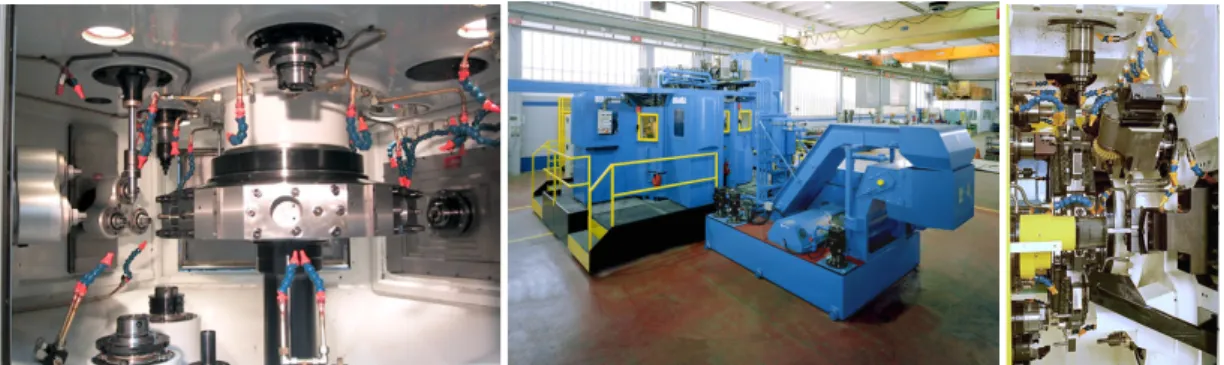
Among them, one of the most prestigious is the hydrostatic unit, in which spindle assembly is contained in a sliding tube supported by a set of hydrostatic bushings. In this paper we will detail the design of a “research & test” bench whose aim is to help in developing new hydrostatic bushing systems and check production units, for quality issues.
2. Scientific contribution
The overall theory of hydrostatic bearings has been developing since the fifties [1]-[6], but a detailed model quite useful for troubleshooting activities is still missing. The theories usually referred to in literature, at least known by the authors, are quite reliable with reference to quasi-static sliding applications, but not satisfying with reference to vibration problems. This is especially true when a system is to be designed with special reference to periodic vibrations induced by the mechanical system supported by the hydrostatic bearing device. Furthermore the use of hydrostatic bearings is increasing in interest for small & medium companies, which don’t handle complex virtual models very well. Moreover, virtual models must be validated and their parameters calibrated [7] before use. This paper gives evidence of the work performed to design and develop a test bench fit to test hydrostatic bearings in order to validate a mathematical model. This latter model is still in development.
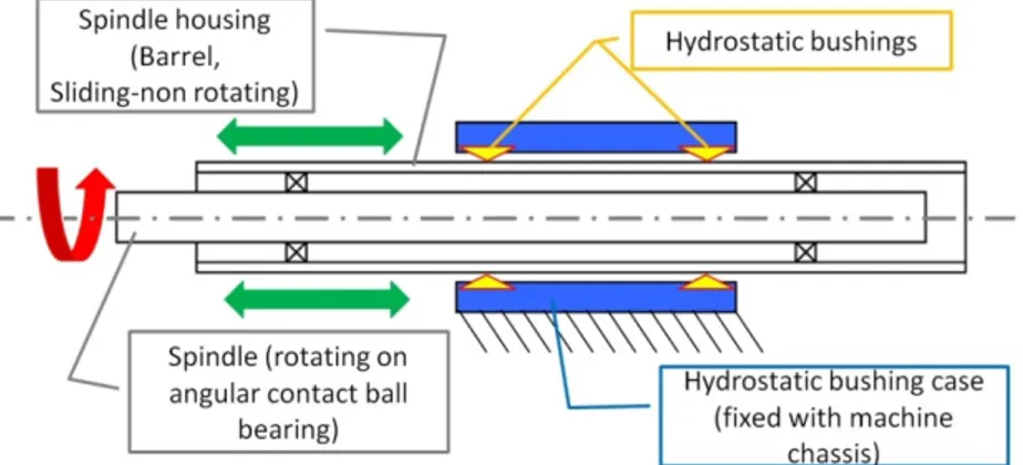
The case study refers to a complete hydrostatic unit assembly for machining purpose (fig 3). In the case it is especially important to be able to foresee the equivalent dynamic model in terms of mass-spring-dampers, where neither springs nor dampers are expected to be linear.
3. Hydrostatic bushing & bearings
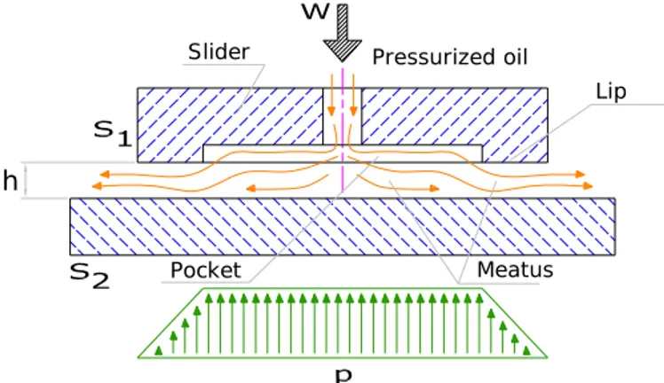
Best lubrication results coincide with the continuous presence of a persistent lubricant film (also named “meatus”), (fig.2) avoiding surface contact and with its own pressure larger than dry contact pressure. To obtain such a result, it is possible to send pressurized lubricant between contact surfaces; if pressure is high enough (more than contact pressure) it detaches surfaces and fluid exits from surface borders. Lubrication layer persists until pressure is applied, and its internal pressure is variable between inlet pressure and external pressure; pressure resultant equilibrates force “W” pushing surfaces one to the other.
Pressurized oil Slider
Pocket Meatus
Lip
h
Figure 2: Hydrostatic lubrication
This lubrication procedure is named “Hydrostatic” and is generally carried on by the means of mineral or synthetic oil. It requires a complex and expensive hydraulic circuit, as can be seen in the following paragraphs. On the other side it can guarantee a perfect lubrication even during machine start, idling and stop, when relative speed between moving parts is too low to create dynamic lubrication. In order to guarantee a minimum surface area where oil can exploit its pressure, even when working surfaces are in contact, it is necessary to insert some “pockets” with a certain area for pressurized oil (often in “non-mobile” surfaces, fig.2). Their number, shape, depth and feeding techniques are parameters to work in order to set for optimum performances, in particular feeding.
In the case of rotating and/or sliding surfaces, every hydrostatic cylindrical bushing comprises a number of 3-6 radial pockets, each with its own oil feeding (typically through chokes). It is important to say that hydrostatic cylindrical bushing allows for rotation and also for internal shaft axial sliding.
4. Application and problems in rotary transfer machines
As aforementioned in a typical transfer machine there are tens of working units and many of them are “hydrostatic units”. Due to competitive advantage, we can not detail here the unit’s internal morphology and strategic devices, but it is possible to describe its general lay out.
It can be considered as a mixed technology application (fig.3). In fact an external bushing body is fixed to unit’s frame, this body containing two sets of circumferential oil pockets. In the bushing body a thick steel tube is oil suspended. It can slide axially but is externally locked in rotation (this tube provides “feeding” motion during machining). Sliding tube itself acts as spindle external case, being internally shaped to hold adequate bearings, with spindle shaft and tool rapid lock-release mechanism. This particular oil application relies actually on a “constant-pressure” feeding, realized by the means of a vane pump with a self adjusting displacement device to guarantee settled pressure supply.
Correct oil flow rate to each single pocket is realized by the means of a manifold connected to a number of chokes, one for each pocket; an ideal feeding condition is equal flow rate to each single pocket. It should be underlined that often, in practical applications, there are historical practices not fully adequate or with high energetic waste, but as aforementioned they will not be discussed here.
Figure 3: Hydrostatic unit’s general lay-out
Working units like these allow for high production rates due to high axial speeds and also due to oil damping characteristics, reflecting in higher feed rates.
Oil must be chosen in accordance with hydrostatic system parameters, geometry and working temperature. The following is a table with typical oil for hydrostatic application.
Table 1: application oil characteristics
Density at 15°C ASTM D 1298 kg/l 0.872
Kinematic Viscosity at 40°C ASTM D 445 mm2/s 45
Kinematic Viscosity at 100°C ASTM D 445 mm2/s 8.4
Viscosity Index ASTM D 2270 - 168
Flash point. ASTM D 92 °C 180
Sliding point ASTM97 °C -36
Figure 4: Errors operating from poligonal bar
Each and every hydrostatic unit is deeply tested before being assembled in a transfer machine, and every modification in design should be tested before application.
Moreover, in some severe marginal conditions, some operating errors can happen. In particular, when operating from a raw polygonal bar, some vibrating interaction could occur between bar, tools and hydrostatic bushing, leading to some defects at the end of first stage of machining (fig.4). Due to company’s attitude to continuous improving in machine performances, the decision to look deeper in
hydrostatic bushing mechanics & dynamics was taken. In particular, this brought on the study, design and construction of a special test bench.
In our research activity we developed and tested a simple complete mathematical model for hydrostatic bushings; it is undergoing validation through the bench here briefly detailed.
5. Important parameters
The aforementioned problem happens as a direct consequence of the traditional approach used in designing hydrostatic bushing. In fact, this approach relies on the calculations of the system’s elastic behaviour under static loads in order to determine components design. This is a limited approach since the suspension “Elastic Characteristic” is not constant during suspended element travel and, more important, it is possible to observe progressive or anti-progressive elastic characteristics only by the means of feeding system. In addition, also damping characteristic is not constant through suspended element travel.
In order to have instruments to determine the hydrostatics design parameters it is therefore necessary to:
Create a mathematical model of a hydrostatic suspended system.
Create an experiment (test bench here described) to test static and dynamic behavior. Determine apparent elastic and damping characteristics to be used in the model. Determine
k =f (s, ω)
andc=f (s, ω)
(1)
Where: k is the suspension elastic characteristic, c is the damping factor, s is the relative movement and
ω
is the movement frequency Validate model with prediction & verification experiments.
In this paper we only discuss the creation of the test bench, while a mathematical model is also in development.
After some months of trial sessions on production units, observing hydro-bushings and their behavior under different conditions, while confronting it with bibliography, our attention focused on some parameters we would like to further investigate (reference fig.2):
Oil Feeding system (pump type, chokes, flux regulators etc) Meatus parameters (lips, “h”, pocket height/lips ratio,…)
Independent and interdependent pockets, this designation depends on how oil leaves working surfaces (if oil flowing from two pockets interacts before decompressing at external pressure level, this is called “interdependent pockets”).
6. Test bench previously in use (static)
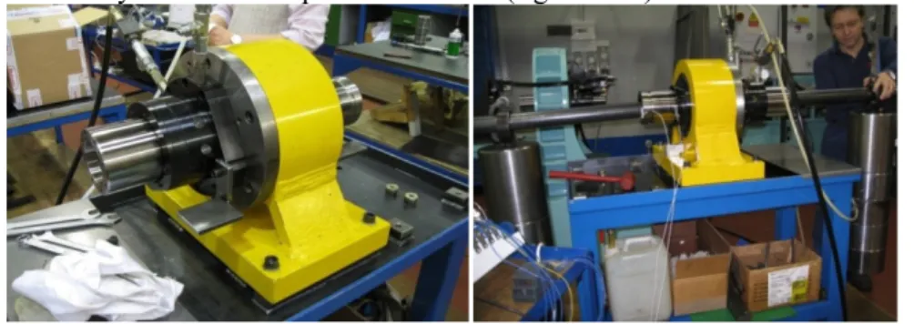
For quality control purposes, a simple test bench has been used for several years in factory, but it can only perform static analysis on normal production units (fig.5 and 6).
Figure 5: Hydrostatic unit’s qualification check
It substantially reproduces a unit’s interface towards machine frame, with faculty to apply loads to a spindle housing tube by the means of a calibrated pole inserted in it.
This simple but useful bench allows only for static and dimensional checks and cannot perform dynamic analysis.
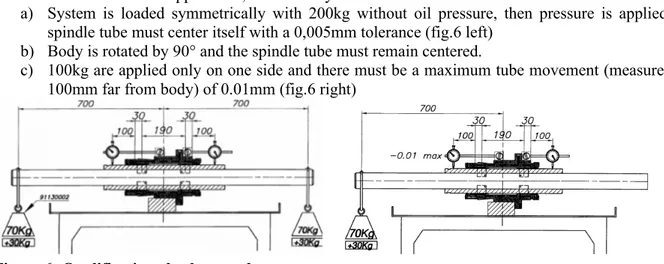
For instance a typical static control is hereby detailed. System is fed by a 50bar constant pressure and, to be declared suitable for application, it must carry out 3 tests:
a) System is loaded symmetrically with 200kg without oil pressure, then pressure is applied: spindle tube must center itself with a 0,005mm tolerance (fig.6 left)
b) Body is rotated by 90° and the spindle tube must remain centered.
c) 100kg are applied only on one side and there must be a maximum tube movement (measured 100mm far from body) of 0.01mm (fig.6 right)
Figure 6: Qualification check procedure
7. Test bench specifications
To deeply investigate hydrostatic phenomena, brand new test equipment was needed. It had to be able to spread through a variety of static and dynamic test conditions. A brainstorming phase was launched after which some major specifications emerged:
Stiffness: there are large forces playing during machining and very small tolerances are required on machined pieces. Therefore, to investigate hydrostatic meatus deformation and relative stiffness, test equipment must almost be 10 times more rigid.
Accessibility: a lot of different configurations should be tested both in mechanics and hydraulics, therefore it should be possible to intervene quickly and inexpensively to change or regulate every single piece of the bench, just like a racing car.
Real machining simulation: possibility to apply a complete spindle assembly to test and monitor real machining operation, and therefore possibility to apply standard grips to handle pieces during this phase.
Regulations of hydraulic parameters: pressure, flow rate, oil viscosity (change oil tank and fill-empty the circuit quickly), oil temperature.
Possibility to adjust chokes dimensions and pressure relief quickly and precisely
Interchangeability of a wide variety of different oil pockets (to test shapes and dimension) Generation of static and dynamic loads independently or together
Test effect of different tool shapes on hydrostatic vibrations
Monitor pressure, acceleration, movement, oil flow in real time during testing and save data for evaluation.
Monitor pressure directly on pocket.
8. Equipment design
General equipment design was conducted in order to reply interfaces between transfer machines and hydrostatic units, to perfectly simulate real use conditions. Therefore, a lay out as depicted in fig. 8 was chosen. It was decided to use a new bushing body: in fact actual standard production bushings have integral pockets, and chokes are also carefully designed to be integrated in external body. This is excellent for production because of its cleanliness and compactness but is very hard to manage when it is necessary to quickly change parameters.
Every minimum modification means a complete disassembly of the bushing and an additional machining to change geometrical pockets parameters.
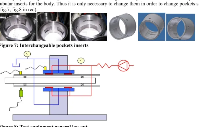
To simplify bushing assembly, in our bench it was redesigned with pocket to be realized as a particular tubular inserts for the body. Thus it is only necessary to change them in order to change pockets shape (fig.7, fig.8 in red).
Figure 7: Interchangeable pockets inserts
Figure 8: Test equipment general lay-out
In conclusion, bushing body has standard assembly external interface, while internal geometry and hydraulic system are completely different, in particular “pockets” systems are realized as inserts. Inserts and their seats have dimensional and geometric tolerances in the order of 1/100mm, to avoid backlashes after assembly while retaining possibility to be disassembled. This is a quite hard requirement to respect because of shape and thickness. As known, it is important to have appropriate sealing (between feeding and exhaust) here realized by means of O-rings.
A first batch of three different inserts was realized with provision for further three to be realized (while first batch was under test). They substantially differ, one from the other, for pockets radial and axial length and for oil blow (by lips length). Test started from standard production geometry, in order to set up and verify equipment parameters.
Also test bench frame was designed with precise goals: firstly this frame has to guarantee maximum clearance for operators to handle experiments set up and parameters changing, then to have as less as possible influence on experiment results and therefore to insulate experiment from external “noise”. In order to achieve these results and initial specifications, a long study phase was launched, to optimize its definitive shape.
Figure 9: Bushing body-frame interface
In the present application, the main problem was to create an interface able to be quickly changed or adjusted in order to receive eventual different shaped machining units, retaining a full accessibility (to handle quick and easy setups). So, interface is composed by a central tubular element with appropriate relief cuts to direct handle hydrostatic sockets; due to company’s patented machining unit fixing
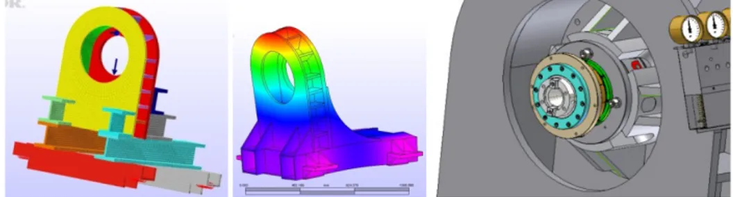
system, there is need to have reinforcing ribs to cope with radial forces generated during assembly. This interface also has some machined spots to receive accelerometers or other instrumentation (fig.9). Then it was necessary to develop the definitive frame, looking at its own vibrating frequencies, with the goal to place them as high as possible, far from supposed hydrostatic bushing and spindle rotating frequencies. In figure 10, some samples of a series of FEM test conducted on various shape frames are enlisted. These put some light on the need to compact masses as possible around unit housing and to create a stiff structure, trying not to use stiffening bracings. In fact bracings, while increasing stiffness in one direction, lowered vibrating frequency in orthogonal direction. (“Algor” was used FEM).
Figure 10: First frame versions-note “free” extremity vibrations
This was due to presence of semi-free structures not linked one to the other, as clearly showed in fig.10, that are responsible to lower resonating frequency.
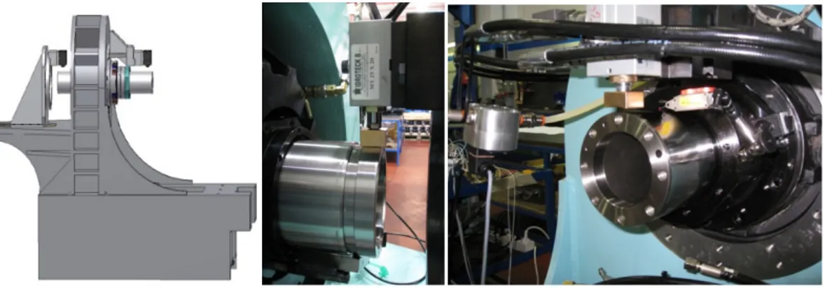
Therefore a ribbed frame model (as depicted in fig.11) was chosen to be more fit to the problem, having no “free floating” parts. This frame has a sandwich structure, very stiff even if, on the other side, it showed less accessibility on hydrostatic bushing. After some FEM iterative work done on it, its resemblance was as in fig.11.
Figure 11: Towards frame final version, right: with machining unit assembled
Among other target to be pursued, there was test bench insulation from external environment and mostly from environmental vibration (this equipment has to be placed in company’s workshop). This goal was achieved through use of air springs. Air springs are normally used in automotive field, alternatively to normal mechanical spring, and are characterized by having a high load capacity with a good damping (due to their rubber body). Operating through their air feeding pressure, it is possible to vary suspension frequency, but typically it is settled around 1hz or less, much lower than any test equipment own frequency, acting in consequence as a low-pass filter from ground to experiment. At the same time, a careful study on how to implement on the test bench appropriate devices to simulate, in realistic way, different machining conditions and static and dynamic loads on hydrostatics was conducted.
This was implemented in the bench by the means of two hydraulic cylinders, acting through copper shaped inserts, on front and aft of the hydrostatic tube; operating (statically or dynamically, through solenoid valves) on their separated oil circuit pressure, various forces combination is applicable (fig.12).
Figure 12: Static and dynamic loading system
On the other side, other extra work was done to design proper accommodation for a complete standard machining unit and raw material fixing clamp, to operate a real machining sequence (fig.13). The result is that, with small time amount, it is possible to dismantle load simulation system and assembly clamp fixture and machining unit simply using a small electric lift truck. Total time amount is estimated to be 1h, followed by unit’s alignment (that is a very delicate operation to be conducted carefully by high skilled personnel).
Figure 13: Final appearance, clamp, “chip-ready”
9. Oil circuit design
Before explaining test bench circuit design, some simple considerations must be done on hydraulics. Considering a stationary laminar flow, Hagen-Poiseuille law is applicable. Here, for a flux between two plates (with pocket insert) with a given h distance, we have ([1], [3], [5])
Q= Δp⋅
h
3L
12ηc
(2)Where Q is oil flow through pocket, L is total pocket border length, c is meatus length and η is fluid viscosity coefficient. We can specify “hydraulic resistance” through meatus as
Rp=12 ηc h3L
with
Δp=R
pQ
(3)For Hagen-Poisseuille law we have, for an l length capillary tube, too
Q= Δp⋅
d
4π
12lη
Δp=R
cQ
Rc=128 ηl
d4π (4)
Considering our hydrostatic bushing basic lay-out, it is possible to develop some calculations on each oil-feeding line (fig 14), looking at its basic scheme (fig 14, right).
Figure 14: Oil schematic circuit, single line pressure and resistances.
Each feeding line corresponds to each single hydrostatic load bearing point; following the scheme (and its electric dual equivalence) we have then:
(
p
o−
p
p)
R
c=
p
pR
pp
pp
o=
1
1+kh
3 k = 128 12 π⋅ lL d4c (5) And consequently to pilot pocket’s pressure we can act on its shape and dimensions (L, c) but also on compensation resistance (l, d; note: d has a cubic exponent). Also interesting is pressure independence from viscosity and then from temperature.For test equipment we invented a simple adjustable compensation system, based on two drilled and threaded blocks with calibrated screw inserted in them. Due to their conformation, in each single channel, oil is forced to pass through calibrated orifice between screw and threaded hole. Continuous resistance variation is feasible rotating screws.
Figure 15: Compensation resistances components and final appearance
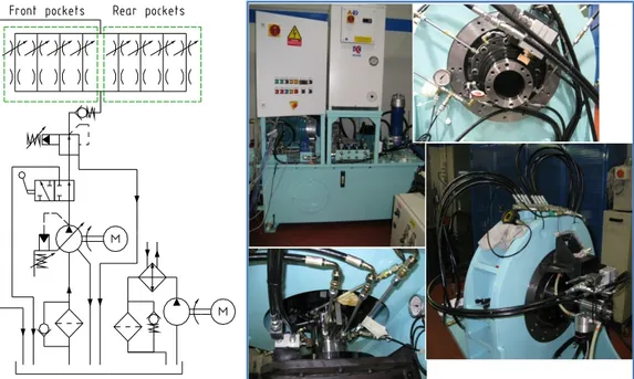
Upstream aforementioned adjustable compensation system, feeding oil system is a bit more complicated than represented in figure 14 because of filtration, oil conditioning, relief and deviation valves. Its complete scheme and appearance is depicted in fig. 16.
Figure 16: Oil system complete scheme and details Conclusions
The proposed equipment was completely studied, designed and tested and it proved to be functional to its targets; in fact it passed the first conformity check, while being fully instrumented with its own data acquisition software. Now the second phase has been launched; in this phase some different experimental campaigns will be carried out to investigate hydrostatic bushing behaviour under different parameters, while using them to calibrate and validate our mathematical model. Report will follow.
References
[1] Bernard J. Hamrock, TECHNICAL HANDBOOK LUBRICATION OF MACHINE ELEMENTS, NASA Reference publication 1126, 1984.
[2] Bassari R., Piccigallo B.; “HYDROSTATIC LUBRIFICATION”; Tribology Series 22, Elsevier, Amsterdam, 1992
[3] Francesco Cotta Ramusino; “MANUALE DELLE MACCHINE UTENSILI”; Tecniche Nuove, Milano. [4] Francesco Cotta Ramusino; “NOTE AL DISEGNO DI GUIDE IDROSTATICHE PER MACCHINE UTENSILI”; Notes.
[5] UCIMU; “LUBRIFICAZIONE IDROSTATICA CUSCINETTI ROTOIDALI”; Comitato sviluppo tecnico, EO
509/1, febbraio 1992
[6] UCIMU; “ LUBRIFICAZIONE IDROSTATICA GUIDE PIANE”; Comitato sviluppo tecnico, EO 509, maggio 1980
[7] Cambiaghi D, Gadola M, Uberti S, Vetturi D, Villa V; PHYSICAL AND VIRTUAL MODEL IN MODERN DESIGN; TMT 2003 - 7th International Research/Expert Conference “Trends in the Developement of Machinery and Associated Technology”; Loret de Mar (Barcelona); Spain; September, 15-16; 2003; ISBN 9958-617-18-8
Dr Stefano Uberti Researcher
Università di brescia, Dipartimento di ingegneria meccanica e industriale. Via branze 38, 25123 Brescia, Italy
+39 030 3715517 +39 030 3702448 [email protected]
http://www.buffoli.com/ http://archimedes.ing.unibs.it/