IOP Conference Series: Earth and Environmental Science
PAPER • OPEN ACCESS
3D-FEM Analysis on Geogrid Reinforced Flexible
Pavement Roads
To cite this article: Lidia Sarah Calvarano et al 2017 IOP Conf. Ser.: Earth Environ. Sci. 95 022024
View the article online for updates and enhancements.
Related content
Geogrid reinforced road subgrade influence on the pavement evenness
A Šiukšius, V Vorobjovas and A Vaitkus
-Design of Road Pavement Using Recycled Aggregate
Eva Remišová, Martin Decký, Milan Mikolaš et al.
-Road pavement condition mapping and assessment using remote sensing data based on MESMA
Y Pan, X Zhang, X Jin et al.
-1
Content from this work may be used under the terms of theCreative Commons Attribution 3.0 licence. Any further distribution of this work must maintain attribution to the author(s) and the title of the work, journal citation and DOI.
Published under licence by IOP Publishing Ltd
1234567890
World Multidisciplinary Earth Sciences Symposium (WMESS 2017) IOP Publishing
IOP Conf. Series: Earth and Environmental Science 95 (2017) 022024 doi :10.1088/1755-1315/95/2/022024
3D-FEM Analysis on Geogrid Reinforced Flexible Pavement
Roads
Lidia Sarah Calvarano 1, Rocco Palamara 1, Giovanni Leonardi 1, Nicola Moraci 1
1 Mediterranea University of Reggio Calabria, Italy [email protected]
Abstract. Nowadays, the need to increase pavement service life, guarantee high performance,
reduce service and maintenance costs has been turned a greater attention on the use of reinforcements. This paper presents findings of a numerical investigation on geogrid reinforced flexible pavement roads, under wheel traffic loads, using a three-dimensional Finite Element Method (FEM). The results obtained show the effectiveness of glass fibre grids as reinforcement which, with appropriate design and correct installation, by improving interface shear resistance, can be used to expand the performance of flexible pavements in different ways: by increasing the road service life providing a relevant contribution against superficial rutting or by decreasing the construction costs due to the reduction in the reinforced HMA layer thickness and thus of mineral aggregate required for its construction.
1. Introduction
Transportation infrastructure plays a vital role in the economic and social life of all countries. The quality and efficiency of road surface play a very efficient role in populations’ development, allowing the easy mobility of people and goods. In particular, this portability provides a better access to jobs, health, education, resources and markets supporting the growth of quality of life and reducing poverty. Flexible pavements can be defined as layered systems that include materials on top that have higher qualities than those towards the bottom thus allowing redistribution of traffic loads from the contact surface to the underlying layers. As pavement flexes under the load, stresses are redistributed over a greater area than that of the tire-footprint. Generally, flexible pavement roads consist of a relatively thin wearing surface layer of asphalt concrete material (Hot-Mix Asphalt, HMA) built over a base course and sub-base course, and they rest upon a compacted subgrade. The main function of the surface layer is to provide a running surface capable of carrying wheel loads without undue discomfort to drivers. It also protects the underlying layers from adverse weather conditions and provides the necessary skid resistance for ensuring road safety characteristics when braking becomes necessary. The base layer is the main load carrying structural component in a flexible pavement. It is designed to resist and distribute stresses induced by vehicles to the underlying layers. While the role of the sub-base layer is to help in distributing induced stresses into the subgrade as well as protecting the sub-base from adverse soil conditions that may prevail in the natural soil. The subgrade is the natural or improved ground on which the pavement structure is constructed.
In recent years, both old and new road infrastructures suffer high traffic volumes, which accelerate degradation and the loss of the structural and functional characteristics of pavements. Thus, in order to rehabilitate and/or improve pavement mechanical performance, geosynthetic reinforcements can be introduced between the pavement layers. The term “reinforcement” refers to the ability of an interlayer
1234567890
World Multidisciplinary Earth Sciences Symposium (WMESS 2017) IOP Publishing
IOP Conf. Series: Earth and Environmental Science 95 (2017) 022024 doi :10.1088/1755-1315/95/2/022024
to better distribute the applied load over a larger area and to compensate for the lack of tensile strength within the road pavement. As in any reinforcement application, the reinforcing material should be stiffer than the material being reinforced. Geosynthetic materials that are widely used for road applications are geogrids for their ability to increase fatigue resistance, reduce rutting and limit reflective cracking.
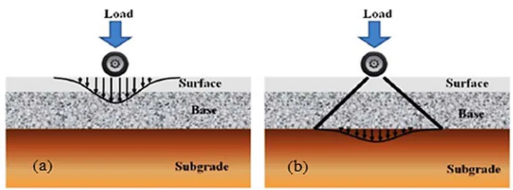
Figure 1 shows the stress redistribution under the wheel load. The design of flexible pavement pays particular attention to two critical locations within the pavement structure, where the reinforcement use may be required: (a) at the bottom of the asphalt layer where the horizontal tensile strain should be minimized in order to prevent fatigue cracking and rutting, and (b) on the top of subgrade where the vertical stress should be minimized in order to reduce permanent deformations [1]. This study focuses on the effectiveness of geogrid reinforcement in the former case.
Figure 1. Stress distributions with depth in a flexible pavement: (a) high stress area directly under wheel load; (b) reduced load at subgrade level [1]
2. Pavement distress
The quality and efficiency of road surface have to allow a comfortable, fast and cheap way to travel from one place to an another, but due to their constant usage, in the long term, the road pavement surface exhibits distress.
Pavement surface deterioration is a process by which defects develop in the pavement under the combined effects of traffic loading and environmental conditions. Traffic loads result from the repetition of wheel loads, which can cause either structural or functional failure. Environmental loads are induced by climatic conditions, such as variations in temperature or moisture in the subgrade, which can cause surface irregularities and structural distress. Anyway, deterioration of pavement greatly effects on serviceability (which requires reactive repairs, road closures and costly resurfacing), safety, and riding quality of the road.
During its life period the pavement structure is vulnerable to different kinds of distresses. The main distress mechanism types of flexible pavements are cracking and rutting.
Cracking is an important common distress that appears in asphalt pavement surfaces roads. The causes are due mainly to the fatigue of the asphaltic pavement layers but other important causes include: adverse atmospheric conditions (shrinkage due to extremely low atmospheric temperatures); bad quality in the asphaltic mixtures production; weakness in the structural pavement resistance.
Rutting (figure 2), which it is the focus of this analysis, is defined as progressive accumulation of longitudinal permanent deformation, or plastic movement, of the surface pavement. It accrues under the action of repeated tire pressures due to the channelized heavy traffic loading over the wheel-tracks of vehicles. Nowadays, it is recognized to be one of the main distress mechanism in flexible pavements as a result of increase in tire pressures and axle loads. Water collects in these depressions and cannot drain freely off the pavement surface. This could cause aquaplaning and therefore rutting is also a potential safety hazard.
Generally rutting may be caused by insufficient design thickness of the pavement, lack of compaction of the subgrade, weakness in the pavement layers due to moisture infiltration, weak
3
1234567890
World Multidisciplinary Earth Sciences Symposium (WMESS 2017) IOP Publishing
IOP Conf. Series: Earth and Environmental Science 95 (2017) 022024 doi :10.1088/1755-1315/95/2/022024
asphalt mixtures or, as mentioned above, by load induced stresses. It can occur in any of the pavement layers or in subgrade one. In particular, if rutting phenomena occur in asphalt layer can be described as a two-stage process, namely, consolidation (densification) which is concerned with volume change of asphalt layer and shape distortion. In particular, initial stage is that of densification of the bituminous concrete under moving traffic, while, the second stage is resulted due to plastic flow of bituminous concrete.
Figure 2. Rutting distress 3. The use of reinforcement in flexible pavement
In order to optimize maintenance interventions costs and increase pavement service life, innovative technical solutions have been developed. One of the most widespread techniques of road-improvement consists in the application of geogrids at the interface between different layers of pavement structures. Geogrids provide different performance depending on their characteristics, such as constituent materials, surface coating, mesh geometry and dimensions, and on their position in the pavement structure. The idea to reinforce paved roads is based on the general concept that if the asphalt layer is strong in compression and weak in tension, then reinforcement could be used to provide needed resistance to tensile stresses, in the same manner as reinforced concrete. Thus, to rehabilitate and/or improve flexible pavement mechanical performance, geosynthetic reinforcements can be introduced between the flexible pavements layers enhancing fatigue resistance, reducing rutting and limiting reflective cracking. Geosynthetic reinforcement in asphalt concrete layers adds tensile strength to the resulting composite material by increasing its capacity to absorb energy during repeated loading cycles proportionally to the geosynthetic tensile strength [2, 3]. Geogrids, also, contribute to the lateral restraining effect of pavements due to the interlocking whose degree depends on the relationship between geogrid aperture size and aggregate particle size, geogrid aperture shape; shape and stiffness of ribs [4-16], instead, the effectiveness of interlocking depends on the in-plane stiffness (more than strength) of the geogrid and the stability of the geogrid ribs and junctions.
Therefore, with appropriate design and correct installation, reinforcement role is to take over part of shear strains, thus, reducing the effect of rutting on HMA. For this purpose, the high tensile strength and the high elastic stiffness of glass fibre grids have been made them an attractive choice for reinforcing pavement systems [17]. Penman and Hook [18] described how glass-fibre based geogrids had been successfully used as interlayers to extend the design life of asphalt pavements on airport runways, taxiways and aprons. Ling and Liu [19] observed that the stiffness and bearing capacity of the asphalt concrete pavement were increased in presence of geogrid at the bottom of the asphalt concrete layer. The geogrid stiffness and its interlocking with the asphalt concrete contributed to the restraining effect. The developed strains in the geogrid around the vicinity of the loading area manifested the restraining effect of geogrid. Moreover, there was a reduction in permanent deformation over the loading area of reinforced pavement compared with that of unreinforced pavement.
A finite element analysis of pavement structures could be a powerful and extremely useful tool to simulate their response when subjected to repeated vehicular traffic loads. This study aims at
1234567890
World Multidisciplinary Earth Sciences Symposium (WMESS 2017) IOP Publishing
IOP Conf. Series: Earth and Environmental Science 95 (2017) 022024 doi :10.1088/1755-1315/95/2/022024
investigating, by means of numerical simulations, the performance of flexible pavement reinforced by geogrid under traffic load repetitions. The use of geosynthetic reinforcements improves the performance of reinforced paved roads in different ways. In fact, the focus of this analysis is to show how the use of glass fibre grids improve the performance of flexible HMA pavements providing a relevant contribution against rutting phenomena, increasing lateral restraint ability, which results in increased pavement service life. On the other hand, the benefit offered by the use of glass fibre grids leads to an HMA layer reduction base thickness, to carry the same number of load repetitions, with a consequent saving of aggregate material needed for its construction and consequently a reduction in the road construction costs.
4. Numerical modelling of geogrid reinforced flexible pavement roads
With the increased advancement in personal computer technology, during the last decades, finite element methods (FEM) offer the potential for thorough and comprehensive analyses of flexible pavement systems at an affordable cost.
Wathugala et al. [20] used the ABAQUS finite element program to explore the decrease in the rut depth of reinforced flexible paved sections. In particular, three locations of the geosynthetic reinforcement were studied: at the base–asphalt concrete interface, at the base–subgrade interface, and inside the base layer at a height of 1/3 of its thickness from the bottom. It was found that placing the geosynthetic reinforcement at the base–asphalt concrete interface leads to the highest reduction of the fatigue strain (46–48%).
The use of FEM in determining the stresses, strains and deflections is becoming widely popular thanks its ability to handle structures with non-linear materials. However, in a lot of these simulations, the traffic loading is generally considered as static one. The incorporation of traffic loading as a dynamic loading is still in its early stages of research.
In addition, a lot of previous studies are referred to bi-dimensional (2D) numerical analysis than three-dimensional (3D) one. The reason is due because this last requires considerably more computational time and powerful and expensive computers. However, the necessity of adopting the 3D analysis arises from the following advantages [21]: i) it better reflects the complex behaviour of the composite pavement system materials under different configurations traffic loads; ii) it is preferred when verifying numerical model results with laboratory or field test results; iii) it allows the simulation of the loaded wheel footprint.
For example, 3D dynamic finite element model was used in the study conducted by Zaghloul [22] to investigate the response of moving loads on pavement structures. The authors used a visco-elastic model for the asphalt concrete, an extended Drucker-Prager model for granular base course and Calm Clay model for the clay subgrade soils. On the other hand, Zaman et al. [23] successfully developed a visco-elasto-plastic creep model representing the time-dependency of asphalt mixtures to evaluate their rutting potential and to identify factors having a significant effect. Buonsanti and Leonardi [24] used a 3D FE model to investigate the behaviour of airport pavements under impulsive loads. The authors modelled the sub-base and subgrade layers using the Mohr-Coulomb material model. In recent years, researchers have been successfully applying linear-viscoelastic theory to describe the behaviour of HMA materials. Elseifi et al. [25] conducted a comparative study between the elastic FE model and the linear viscoelastic FE model and concluded that it is imperative to incorporate a viscoelastic constitutive model into pavement design methods for improved accuracy. Yin et al. [26] showed that 3D finite element modelling utilizing viscoelastic material properties provides reasonable prediction of strain response in the field. Al-Qadi et al. [27] showed the effectiveness of using a nonlinear time-hardening creep model to compute permanent deformation.
On the basis of the aforementioned considerations, this paper aims at providing a numerical investigation using a three-dimensional (3D) Finite Element Method, using ABAQUS software, to analyse the improvement, in terms of reduction of rutting and saving of mineral aggregate, of a flexible HMA pavement reinforced by a glass fibre grid, under repeated wheel traffic load conditions.
5
1234567890
World Multidisciplinary Earth Sciences Symposium (WMESS 2017) IOP Publishing
IOP Conf. Series: Earth and Environmental Science 95 (2017) 022024 doi :10.1088/1755-1315/95/2/022024
The method takes into account reinforcement stiffness, interface properties, geometrical and mechanical properties of HMA, base, sub-base and subgrade layers, and finally traffic conditions.
4.1 Model geometry
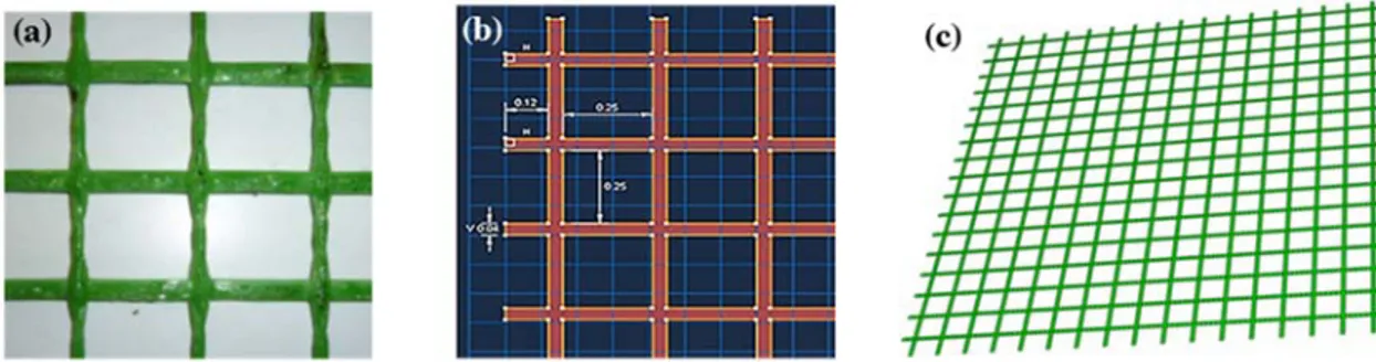
Three paved road sections were simulated. Two unreinforced sections that differ each other in HMA layer thickness (respectively equal to 0.08 m and 0.12 m). One reinforced paved section, for which the HMA layer is thick 0.08 m and where a glass fibre grid was placed at the HMA-base interface. In all the flexible paved sections simulated the thicknesses of the others layers such as the base, the sub-base and the subgrade were chosen and fixed, respectively, equal to 0.20 m, 0.27 m and 1.45 m.
Figure 3. Glass fibre grid layer: a) plane view; b) open meshes dimension; c) mesh model In particular, a three-dimensional model for a typical flexible pavement section (figure 4a), in ABAQUS software, is composed by an asphalt concrete (HMA) surface layer, a base layer, a sub-base layer and a sandy subgrade layer, which are all simulated by 3D deformable solid extrusion elements (solid homogeneous section type). In the reinforced section, the glass fibre grid placed at HMA-base interface was simulated by 3D deformable shell planar (membrane elements section type) with thickness of 0.003 m and with open meshes (figure 3a ÷ figure 3c).
4.2 Load and boundary conditions
Traffic load conditions are the main factors affecting the pavement system designing, depending on axial loads, configuration of axles, tire contact areas, number of load repetitions, vehicle speed. Certainly, the heavy vehicular traffic, as that of the trucks, definitely is a primary cause of pavement distresses and failure. For loading area, wheel load can be applied on the entire wheel path, anyway generally, the most common way of applying wheel load, in both theoretical and numerical analysis, is to apply tire pressure loads, uniformly distributed, to a circular or rectangular equivalent contact area defined in function of the wheel load and of the tire contact pressure. To simulate the wheel applied cyclic load, generally, equivalent, pulse, and moving loading are the most common methods used.
Therefore, based on the above considerations, to simulate a heavy vehicular traffic, a loading of impulse type was assumed with a number of repetitions (Ncycles) equal to 2000. Its amplitude is equal to one-half of an axle load (PAxle=80 kN, so it is equal to 40 kN), resulting in a pavement pressure (Pc) of 550 kPa acting on a circular area of 0.15 m radius. A frequency of 10 Hz was chosen since this impulsive load with a duration of 0.1 second corresponding to an average speed of around 70 km/h.
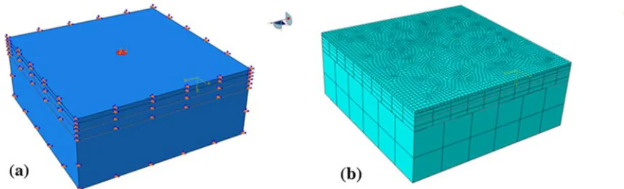
The boundary conditions (figure 4a) chosen for the model are the following: i) model constrained at the bottom; ii) displacements in x direction and rotations in y and z directions prevented on the sides parallel to y-axis; iii) displacements in y direction and rotations in x and z directions prevented on the sides parallel to x-axis. The degree of mesh refinement is important to estimate an accurate stress field in the pavement road section, so the densest mesh is required for the superficial layer, on which the load is applied, to better capture the permanent displacements (figure 4b). Eight-node linear brick elements (C3D8R) were used to mesh all pavement layers (figure 4b), whereas four-node quadrilateral membrane elements (M3D4) were used to mesh the glass fibre grid (figure 3c).
1234567890
World Multidisciplinary Earth Sciences Symposium (WMESS 2017) IOP Publishing
IOP Conf. Series: Earth and Environmental Science 95 (2017) 022024 doi :10.1088/1755-1315/95/2/022024
Figure 4. Three-dimensional view of the finite element model: a) load area and boundary conditions; b) mesh model
4.3 Material behaviour and constitutive laws
The materials data required in the FEM simulations are listed in table 1. They have been assumed to be realistic, as much as possible, as published in previous literature studies [28, 29].
Table 1. Mechanical materials data and model parameters used in the FEM analysis for each flexible pavement section layer.
Model HMA Base Sub-base Subgrade Geogrid
Modulus of elasticity [Pa] 1.9x10⁹ 300x106 41x106 10x106 28x109
Poisson’s ratio [-] 0.35 0.35 0.3 0.3 0.3
Dilatant angle [°] 10 0
Yield stress [Pa] 20000 20000
Creep parameters: A 1 x10⁻⁹
m 0.67
n -0.5
In order to evaluate creep deformations of HMA layer a nonlinear time-hardening creep model that better describes the HMA behaviour was implemented. About the geogrid and the base layer a linear elastic constitutive model was assumed. Finally, for the remaining layers (i.e., sub-base and subgrade) a modified Drucker-Prager model with hyperbolic yield criterion was used. Five interfaces between the pavement section layers were modelled. The choice of the interface mechanical characteristics has a key role because it significantly affects the response of the model depending on the type of contact that is considered. In the reinforced section, as regards the behaviour at the HMA-geogrid interface and at geogrid-base interface, the interaction is due to a tangential component and a normal one. About the normal component, a hard contact type behaviour was assumed, while, in the tangential direction a penalty type behaviour with a coefficient of friction equal to 1.5 was chosen.
With respect to the unreinforced configuration the same interface constitutive law at HMA-base interface was used. In order to simplify the model, the other contact surfaces (i.e., base-sub-base interface and sub-base-subgrade interface) were defined as tie constraint, able to ensure a perfect ad adherence to each interface, limiting both the relative displacements and the rotations.
5. FEM analysis results and discussions
To investigate the performance of a reinforced flexible pavement road, a series of 3D-finite element dynamic simulations were carried out, at equivalent traffic conditions, in order to evaluate the benefits offered by the glass fibre grid, placed at HMA-base interface, against permanent deformations (rutting) and in term of reduction in the reinforced HMA layer thickness.
7
1234567890
World Multidisciplinary Earth Sciences Symposium (WMESS 2017) IOP Publishing
IOP Conf. Series: Earth and Environmental Science 95 (2017) 022024 doi :10.1088/1755-1315/95/2/022024
Figure 5. Total permanent displacements [m] after 2000 cycles of impulsive wheel loading relating: a) unreinforced section with 0.08 m HMA thickness; b) unreinforced section with 0.12 m HMA thickness; c) reinforced section with 0.08 m HMA thickness and glass fibre grid placed at HMA-base
interface; d) deformed configuration of glass fibre grid
Figure 5a ÷ figure 5d show the results of these simulations, where the vertical permanent displacements are considered as a response of applying repeated loads and of the number of loading repetitions. In details, figure 5a and figure 5b show, respectively, the deformed configuration for the unreinforced flexible paved section with 0.08 m and 0.12 m HMA thickness. The final vertical surface displacements under the load center, after 2000 cycles of loading, are respectively about 0.0035 m and 0.0031. Therefore, this first comparison shows how an increase in HMA thickness layer of about 33%, (which means higher construction cost) with the purpose to increase the road service life, give only 10% of surface rutting reduction, thus does not lead to an evident extension of pavement performance. Figure 5c shows the deformed configuration for the flexible paved road section reinforced with the glass fibre grid placed at HMA-base interface. At the same traffic condition (i.e., Ncycles=2000), under the center-line of the wheel load, a vertical permanent surface displacement, or rutting, about of 0.0015 m was computed. This result is very interesting because the comparison with the above unreinforced paved sections emphasizes the effectiveness of reinforced flexible pavement technique respect the traditional one. In particular, comparing the unreinforced paved section, relating the configuration (a) with 0.08 m HMA layer thickness (figure 5a) with the corresponding reinforced one (i.e., configuration (c), figure 5c), it has been observed an improvement in term of reduction of rutting about of 57% that means an important increase of the service road life, in according to the serviceability criteria. On the other hand, the comparison between the unreinforced paved section with 0.12 m of HMA layer (figure 5b) with the reinforced one composed of a HMA layer less thick (i.e. 0.08m, figure 5c) shows how an effective flexible paved design solution not necessarily require larger HMA layer thicknesses, but it is enough interposing a geogrid at the bottom of the HMA layer to improve pavement mechanical performance and at the same time with saving of HMA thickness. This design solution that at the same time guarantees high performance reducing the effect of rutting on HMA (of about 53% in this case) leads to a saving of aggregate material required and, therefore, less in-place construction costs. Also, the reinforcement technique of flexible pavement implies other vantages equally important such as: faster time of construction, thus less CO2 atmosphere emissions that lead to lower environmental impact, optimization of maintenance costs due to the defer of periodic rehabilitation interventions thanks the acquired improved reinforced pavement mechanical
(a) (b)
1234567890
World Multidisciplinary Earth Sciences Symposium (WMESS 2017) IOP Publishing
IOP Conf. Series: Earth and Environmental Science 95 (2017) 022024 doi :10.1088/1755-1315/95/2/022024
performance. Finally, figure 5d shows the deformed configuration of the glass fibre grid at the end of impulsive wheel loading after 2000 Ncycles, which the highest vertical displacement is about 0.0014 m.
In detail figure 6 shows the vertical displacements across the transverse section under the center of loading for all the flexible paved road sections simulated. The comparisons, more clearly, confirm the results previously discussed. Therefore, these simulation results show that the proposed model has the capability to capture the pavement responses under repeated loads. This aspect is very important because several agencies adopted the rutting as failure criterion in pavement design.
Figure 6. Vertical permanent displacements [m] for the unreinforced and reinforced flexible pavement sections
6. Conclusions
This paper presents findings of a numerical investigation on geogrid reinforced flexible pavement roads, under wheel traffic loads, using 3D FEM by ABAQUS software.
Three paved road sections, two unreinforced that differ in HMA layer thickness (respectively equal to 0.08 m and 0.12 m) and one reinforced with a glass fibre grid placed at the HMA-base interface and characterized by 0.08 m HMA layer, all subjected to the same impulsive wheel loading, were simulated. On the basis of the 3D FEM analysis the following conclusions could be drawn.
In the traditional flexible paved road design (i.e. unreinforced pavement) is evident that an increase in HMA thickness layer, which means higher construction costs, with the purpose to increase the road service life, give negligible surface rutting reduction, thus does not lead to an evident extension of pavement performance.
Also, under the same traffic conditions (Ncycles=2000) and geometrical and mechanical proprieties of all the pavement layers, the reinforced configuration works better emphasizing the effectiveness of using glass fibre grid as reinforcement respect the traditional one. The use of geogrid, thanks interlocking phenomena, enhancing the tensile strength of asphalt layer leads to a reduction in vertical stresses acting in the underlying layers that implies a reduction of rutting due to the plastic deformations under the action of repeated traffic loads. The presence of the geogrid implies an improvement in terms of surface rutting reduction (of about 57% in this study) when the glass fibre geogrid is placed at HMA-base interface that means an important increase of the service road life, in according to the serviceability criteria.
Also, the results obtained show how an effective flexible paved design solution not necessarily require larger HMA layer thicknesses, but it is enough interposing a geogrid at the bottom of the HMA layer to improve pavement mechanical performance and at the same time with saving of HMA thickness. This design solution, that at the same time guarantees high performance reducing the effect of rutting on HMA, leads to a saving of aggregate material required too and, therefore, less in-place construction costs.
In addition, from an economics point of view, the reinforcement technique of flexible pavement implies other vantages equally important such as: faster time of construction, thus less CO2
9
1234567890
World Multidisciplinary Earth Sciences Symposium (WMESS 2017) IOP Publishing
IOP Conf. Series: Earth and Environmental Science 95 (2017) 022024 doi :10.1088/1755-1315/95/2/022024
atmosphere emissions that lead to lower environmental impact, optimization of maintenance costs due to the defer of periodic rehabilitation interventions thanks the acquired improved reinforced pavement mechanical performance.
Therefore, FEM analysis results could be important to quantify the benefit–cost ratio of geosynthetic application in pavements needed for a detailed life-cycle cost analysis (LCCA) which should include the initial construction, maintenance, and user costs. Since LCCA is a useful economic tool in considering certain transportation investment decisions, this topic could be another potential research subjects.
References
[1] J.G. Zornberg, and R. Gupta, “Geosynthetics in Pavements: North American Contributions,”
Proceedings of the 9th Inter.Conference on Geosynthetics, vol. 1, pp. 379-400, 2010.
[2] A. Mahrez, M.R. Karim, and H.Y. Katman, “Fatigue and Deformation properties of Using Glass Fiber Reinforced Bituminous Mixes,” Journal of the Eastern Asia Society for Transportation
Studies, vol. 6, pp. 997-1007, 2005.
[3] E. Pasquini, M. Bocci, G. Ferrotti, and F. Canestrari, “Laboratory characterization and field validation of geogrid-reinforced asphalt pavements,” Road Mater Pavement, vol. 14, pp. 17– 35, 2012.
[4] J. P. Giroud, C. A h-Line, and R. Bonaparte, “Design of unpaved roads and trafficked areas with geogrids, Polymer grid reinforcement,” Thomas Telford Limited, London, 1985.
[5] J. P. Giroud, and J. Han, “Design method for geogrid-reinforced unpaved roads. I. Development of design method,” J. Geotech. Geoenviron. Eng., vol. 130 (8), pp. 775-786, 2004.
[6] D. Cazzuffi, L.S. Calvarano, G. Cardile, N. Moraci, and P. Recalcati, “European experience in pullout tests: The influence of geogrid’s geometry and structure on interface behaviour,”
Geosynthetics, vol. 29 (5), pp. 42- 51, 2011.
[7] D. Cazzuffi, N. Moraci, L.S. Calvarano, G. Cardile, D. Gioffrè, and P. Recalcati, “The influence of vertical effective stress and of geogrid length on interface behaviour under pullout conditions.” Geosynthetics, vol. 32 (2), pp. 40-50, 2014.
[8] N. Moraci, D. Cazzuffi, L.S. Calvarano, G. Cardile, D. Gioffrè, and P. Recalcati, “The influence of soil type on interface behavior under pullout conditions,” Geosynthetics, vol.32(3), pp. 42-50, 2014.
[9] N. Moraci, G. Cardile, D. Gioffrè, M.C. Mandaglio, L.S. Calvarano, and L. Carbone, “Soil Geosynthetic Interaction: Design Parameters from Experimental and Theoretical Analysis,”
Transportation Infrastructure Geotechnology, vol. 1 (2), pp. 165-227, 2014.
[10] L.S. Calvarano, D. Gioffrè, G. Cardile, and N. Moraci, “A stress transfer model to predict the pullout resistance of extruded geogrids embedded in compacted granular soils,” In
proceeding of 10th ICG 2014, Berlin, Germany, 2014 .
[11] G. Cardile, L.S. Calvarano, D. Gioffrè, N. Moraci, Experimental evaluation of the pullout active length of different geogrids, In proceeding of 10th ICG 2014, Berlin, Germany, 2014 . [12] L.S. Calvarano, R. Palamara, L. Leonardi, and N. Moraci, “Unpaved road reinforced with
geosynthetics,” Procedia Engineering, Elsevier, vol. 158, pp. 296-301, 2016.
[13] L.S. Calvarano, G. Leonardi, and R. Palamara, “Finite element modelling of unpaved road reinforced with geosynthetics,” Procedia Engineering, Elsevier, vol.189, pp. 99-104, 2017. [14] L.S. Calvarano, N. Moraci, L. Leonardi, and R. Palamara, “Reinforced unpaved roads:
Parametrical analysis of design procedures,” 6th
European Geosynthetics Congress Proceedings (EUROGEO 6), Ljubljana, Slovenia, pp.1147-1155, September 25-28, 2016.
[15] G. Cardile, N. Moraci, and L.S. Calvarano, “Geogrid pullout behaviour according to the experimental evaluation of the active length,” Geosynthetics International, vol. 23 (3), pp. 194- 205, 2016.
[16] G. Cardile, D. Gioffrè, N. Moraci, L.S. Calvarano, “Modelling interference between the geogrid bearing members under pullout loading conditions,” Geotextiles and Geomembranes, vol. 45
1234567890
World Multidisciplinary Earth Sciences Symposium (WMESS 2017) IOP Publishing
IOP Conf. Series: Earth and Environmental Science 95 (2017) 022024 doi :10.1088/1755-1315/95/2/022024
(3), pp.169-177, 2017.
[17] G. Leonardi, M. Buonsanti, F. Scopelliti, “Theoretical and computational analysis of airport flexible pavements reinforced with geogrids,” Mechanisms, Modeling, Testing, Detection
and Prevention Case Histories, RILEM Bookseries, Springer
[18] J. Penman, and K. Hook, “The use of geogrids to retard reflective cracking on airport runways, taxiways and aprons,” Pavement Cracking. Mechanisms, Modeling, Detection, Testing and
Case Histories, CRC Press, 2008.
[19] H. I. Ling, and Z. Liu, “Performance of geosynthetic-reinforced asphalt pavements,” J. Geotech.
Geoenviron. Eng., vol. 127 (2), pp. 177-184, 2001.
[20] Wathugala, G. W., B. Huang, and S. Pal (1996) “Numerical simulation of geogrid reinforced flexible pavements,” Transportation Research Record 1534, Washington, D.C., pp 58–65. [21] B. Saad, H. Mitri, and H. Poorooshasb, “Threedimensional dynamic analysis of flexible
conventional pavement foundation,” J.of Transportation Engineering, vol. 131 (6), pp.460– 469, 2005.
[22] S. Zaghloul, “Non-Linear Dynamic Analysis of Flexible and Rigid Pavements,” ETD Collection
for Purdue University, West Lafayette, 1993
[23] M. Zaman, S. Pirabaroban, and R. Tarefder, “Evaluation of rutting potential in asphalt mixes using finite element modelling,” in Transportation Association of Canada, 2003.
[24] M. Buonsanti, and G. Leonardi, , “FEM Analysis of Airport Flexible Pavements Reinforced with Geogrids,” Advanced Science Letters, vol. 13 (1) , pp. 392-395, 2012.
[25] M.A. Elseifi, I.L. Al-Qadi, and P.J. Yoo, “Viscoelastic modeling and field validation of flexible pavements,” J. Engineering Mechanics, vol. 132 (172), pp. 172-178, 2006.
[26] H. Yin, S. Stoffels, and M. Solaimanian, “Optimization of asphalt pavement modeling based on the global-local 3D FEM approach,” Road Materials and Pavement Design, vol. 9, pp. 345-355, 2008.
[27] I. L. Al-Qadi, P.J. Yoo, M.A. Elseifi, and S. Nelson, “Creep behavior of hot-mix asphalt due to heavy vehicular tire loading,” J. Engineering Mechanics, vol. 135, pp. 1265–1273, 2009. [28] G. Leonardi, “Finite element analysis for airfield asphalt pavements rutting prediction,” Bulletin
of The Polish Academy of Sciences Technical Sciences, Vol. 63 (2), pp. 397-403, 2015.
[29] L. Leonardi, R. Palamara, and L.S. Calvarano, “Numerical analysis of flexible pavement reinforced with geogrids,” Internat. Conf. on highway pavements & airfield technology

![Figure 5. Total permanent displacements [m] after 2000 cycles of impulsive wheel loading relating: a) unreinforced section with 0.08 m HMA thickness; b) unreinforced section with 0.12 m HMA thickness; c) reinforced section with 0.08 m HMA thickness and g](https://thumb-eu.123doks.com/thumbv2/123dokorg/5024879.55647/8.892.111.807.169.494/permanent-displacements-impulsive-unreinforced-thickness-unreinforced-reinforced-thickness.webp)
![Figure 6. Vertical permanent displacements [m] for the unreinforced and reinforced flexible pavement sections](https://thumb-eu.123doks.com/thumbv2/123dokorg/5024879.55647/9.892.168.726.324.533/vertical-permanent-displacements-unreinforced-reinforced-flexible-pavement-sections.webp)
