UNIVERSITÀ DEGLI STUDI CATANIA
INTERNATIONAL PhD IN CHEMICAL SCIENCES
XXX CYCLE
Roberto Fiorenza
Modified TiO
2-based catalysts for energy production
and environmental protection
Laboratory of Environmental and Industrial Catalysis
Department of Chemical Sciences
Università degli studi di Catania
PhD COORDINATOR: Prof. S. Sortino
TUTOR: Prof. S. Scirè
- 1 -
INTRODUCTION ... - 3 -
- Energy in Europe: The 20-20-20 goal ... - 3 -
- New technologies for the environmental protection and the energy production ... - 5 -
References ... - 7 -
Chapter 1: Heterogeneous Photocatalysis ... - 8 -
1.1 Principles of photocatalysis ... - 8 -
1.2 Photo-oxidation of organic contaminants in air ... - 12 -
1.3 Photo-oxidation of organic contaminants in water ... - 16 -
1.4 Photocatalytic water splitting ... - 19 -
References ... - 25 -
Chapter 2: TiO2-based materials ... - 28 -
2.1 Titanium dioxide ... - 28 -
2.2 Strategy to enhance the TiO2 photoefficiency: Chemical modifications ... - 31 -
2.3 Strategy to enhance the TiO2 photoefficiency: Structural modification of TiO2 ... - 37 -
2.3.1 Reduced TiO2 ... - 37 -
2.3.2 Morphological change of TiO2 ... - 39 -
References ... - 43 -
Chapter 3: Chemical modifications of TiO2 ... - 46 -
3.1 TiO2-CeO2 based composites ... - 46 -
3.2 Au/TiO2 catalysts ... - 47 -
3.3 Au/TiO2-CeO2 catalysts: Samples preparation and experimental setup... - 49 -
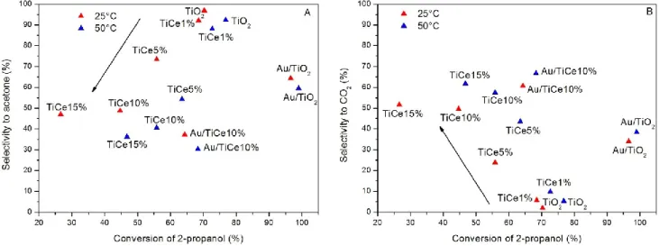
3.3.1 Results and discussion ... - 50 -
3.3.2 Conclusions and future perspectives ... - 59 -
References ... - 62 -
Chapter 4: Structural modifications of TiO2: Reduced TiO2 ... - 64 -
4.1 Laser irradiated TiO2 ... - 64 -
4.2 Samples preparation and experimental setup ... - 64 -
4.3 Results and discussion ... - 65 -
4.4 Conclusions and future perspectives ... - 76 -
References ... - 79 -
Chapter 5: Structural and chemical modifications of TiO2: Inverse Opal TiO2 ... - 80 -
5.1 Photonic crystals ... - 80 -
- 2 -
5.4 Inverse Opal TiO2 based materials: Samples preparation and experimental setup ... - 84 -
5.5 Results and discussion ... - 90 -
5.6 Conclusions and future perspectives ... - 128 -
References ... - 130 -
CONCLUSIONS ... - 133 -
Appendix A: Characterization techniques used in this work ... - 136 -
Appendix B: Gas Chromatography ... - 142 -
Appendix C: Hydrogen Economy ... - 145 -
Curriculum vitae ... - 153 -
List of publications ... - 154 -
List of Communications:... - 156 -
Courses and Schools ... - 158 -
- 3 -
INTRODUCTION
- Energy in Europe: The 20-20-20 goalAir pollution and the increase of energy demand are among the most serious problems of the present days. As a central objective of the Europe 2020 strategy, the European Union (EU) has set the goal to cut greenhouse gas (GHG) emissions by 20%, improve energy efficiency by 20% and increase the use of renewable energy to 20% by the year 2020. This is known as the 20-20-20 goal.
The EU framework on climate and energy for 2030 proposed by the European Commission in January 2014 presents targets that are more ambitious and aims at reducing greenhouse gas emissions by 40% and increasing the use of
renewable to at least 27% by 2030 [1].
The European Commission and EU governments agreed on the target of cutting greenhouse gases (GHG) by at least 20% by 2020, compared with 1990 levels (Fig.1).
In market based economies like the Europeans it is a general problem to get the cost of externalities like GHG and climate change imbedded into the market so that these cost will influence decisions about production, consumption and investment. As highlighted in various climate change assessment studies the future society costs of climate change and global warming are quite high although not evenly
geographical and sector distributed. To better reflect these costs for producers, consumers and investors and make up for part of the market imperfection a European Union Emission Trading System (EU ETS) was designed back in 2003. By putting a price on carbon and thereby giving a financial value to each tone of emissions saved, the EU ETS has placed climate change on the agenda of company boards across Europe. A sufficiently high carbon price also promotes investment in clean, low-carbon and energy efficient technologies. The EU ETS scheme covers the most GHG intensive sector in Europe including the power sector and a number of industrial sectors like cement and steel production, etc. [2]. These sectors accounts for more than 40% of the total GHG emission in Europe. The 2020 climate and energy package includes a
Fig.1 EU greenhouse gas emission in 2014.
- 4 -
comprehensive revision and strengthening of the legislation which underpins the EU ETS, the Emissions Trading Directive. Energy efficiency is the second important point of the 20-20-20 goal. Substantial steps have been taken towards the objective of increasing energy efficiency, notably in the appliances and buildings markets. The new Energy Efficiency Plan [3] aims at responding to the call of the European Council of 4 February 2011 to take determined action to tap the considerable potential for higher energy savings of buildings, transport, products and processes [4]. The energy efficiency measures will be implemented as part of the EU’s wider resource efficiency goal, encompassing
efficient use of all natural resources and ensuring high standards of environmental protection. The greatest energy saving potential lies in buildings whilst transport has the second largest potential. Energy efficiency in industry will be tackled through energy efficiency requirements for industrial equipment and measures to introduce energy audits and energy management systems. Improvements to the efficiency of power and heat generation are also proposed, ensuring that the plan includes energy efficiency measures across the whole energy supply chain. A
wide range of technologies and methods exist to improve energy efficiency, turn renewables into viable energy sources and reduce emissions.
The EU's Renewable energy directive sets a binding target of 20% final energy consumption from renewable sources by 2020. To achieve this, EU countries have committed to reaching their own national renewables targets ranging from 10% in Malta to 49% in Sweden (Fig.2).
They are also each required to have at least 10% of their transport fuels come from renewable sources by 2020.
All EU countries have adopted national renewable energy action plans showing what actions they intend to take to meet their renewables targets. These plans include: sectorial targets for electricity, heating, cooling and transport; planned policy measures and the different mix of renewables technologies that they expect to employ.
Fig.2: Renewable energy in the European Union
- 5 -
- New technologies for the environmental protection and the energy production
Gases that trap heat in the atmosphere are called greenhouse gases and the main are: CO2, CH4,
N2O and the fluorinated gases.The greenhouse effect increases the temperature of the earth by
trapping heat in our atmosphere. This keeps the temperature of the earth higher than it would be if direct heating by the sun was the only source of warming. When sunlight reaches the surface of the earth, some of it is absorbed which warms the ground and some bounces back to space as heat. Greenhouse gases that are in the atmosphere absorb and then redirect some of this heat back towards the earth.The earth’s atmosphere consists mainly of oxygen and nitrogen, neither plays a significant role in enhancing the greenhouse effect because both are essentially transparent to terrestrial radiation. The greenhouse effect is primarily a function of the concentration of water vapor, carbon dioxide (CO2), methane (CH4), nitrous oxide (N2O), and
other trace gases in the atmosphere that absorb the terrestrial radiation leaving the surface of the earth. Changes in the atmospheric concentrations of these greenhouse gases can alter the balance of energy transfers between the atmosphere, space, land, and the oceans. Human activities are continuing to affect the earth’s energy budget by changing the emissions and resulting atmospheric concentrations of radiatively important gases and aerosols and by changing land surface properties. There are also several gases that, although they do not have a commonly agreed upon direct radiative forcing effect, do influence the global radiation budget. These tropospheric gases include carbon monoxide (CO), nitrogen dioxide (NO2), sulfur dioxide (SO2),
and tropospheric (ground level) ozone (O3). Tropospheric ozone is formed by two precursor
pollutants, volatile organic compounds (VOCs) and nitrogen oxides (NOx) in the presence of
ultraviolet light (sunlight).
The term VOCs encompasses many compounds including non-methane hydrocarbons, alcohols, aldehydes and organic acids. Exposure to VOCs may trigger many serious health problems, such as eye, nose, skin, and throat irritation, coughing, headaches, and cancer, even at very low concentrations [5, 6].Therefore; it is highly desirable to efficiently and cost-effectively abate VOCs. Many practical methods, such as adsorption, thermal combustion, catalytic oxidation, and biofiltration, have been adopted to remove hazardous VOCs [7]. Amongst these technologies, catalytic oxidation is believed to be very promising as it is a highly efficient and relatively inexpensive route to reducing VOCs at low concentrations. More importantly, it decomposes VOCs to non-toxic final products, i.e., CO2 and H2O, with high performance and good durability
at lower temperatures (< 600 °C) [8].
Recently, especially applied for the wastewater treatment, the Advanced Oxidation Processes (AOPs) constitute a family of similar but not identical technologies that are based predominantly
- 6 -
(but not exclusively) on the production of very reactive hydroxyl radicals [9]. AOPs include heterogeneous and homogeneous photocatalysis, Fenton and Fenton-like processes, ozonation, the use of ultrasound, microwaves and γ-irradiation, electrochemical processes and wet oxidation processes. One of their main advantages compared to conventional technologies is that they effectively degrade recalcitrant components without generating a secondary waste stream as is the case for example of the membrane processes. Moreover, in most cases the formation of hazardous species in the effluent is limited. This is a specifically important benefit over competing technologies such as for instance chlorine oxidation of organics, during which a considerable amount of organo-chlorinated species is formed [10]. From the turn of the century till now, the number of processes has increased drastically with the development of hybrid synergistic technologies based on the combination of various AOPs.
These combinations have helped to overcome the occurrence of refractory species and also to improve significantly the performance of AOPs, to meet the practical requests in accordance with the green policy of European Union.
Among these new processes, photocatalysis is one of the most attractive advanced oxidation technologies for the decompositions of organic pollutions in water or air [11]. Furthermore in the contest of the other tasks of Europe 20-20-20 (improvement of the energy efficiency by 20% and increasing of the use of renewable energy to 20% by the year 2020) the photocatalytic process can be applied to produce hydrogen or for the CO2 reduction [12].
Hydrogen would play an important role because it is an ultimate clean energy and it can be used in fuel cells. Moreover, hydrogen is used in chemical industries. For example, a large amount of hydrogen is consumed in industrial ammonia synthesis. At present, hydrogen is mainly produced from fossil fuels such as natural gas by steam reforming. In this process, fossil fuels are consumed and CO2 is emitted. Hydrogen has to be produced from water using natural energies
such as sunlight if one thinks of energy and environmental issues. Therefore, the solar hydrogen production from water is one of the most important topics of current research.
On these bases, this work has the aim to investigate the photocatalytic performance of modified TiO2-based materials in some important reactions applied to environment protection and energy
production. In particular much effort has been focused in the photo-oxidation of VOCs in gas phase, in the photodegradation of harmful compounds in water and in the hydrogen evolution by photocatalytic water splitting.
- 7 -
References
[1] G. Liobikien, M.Butkus, Renew. Energ. 106 (2017) 298-309.
[2] Energy and Climate Policies beyond 2020 in Europe- Overall and selected countries Danish Energy Agency; https://ens.dk/sites/ens.dk/files/Globalcooperation/eu_energy_and_climate_policy_overview.pdf
[3] M. Carvalho, Energy 40 (2012) 19-22.
[4] K. Knoop, S.Lechtenböhmer, Renew. Sust. Energ. Rev. 68 (2017) 1097-1105. [5] A.P. Jones, Atmos Environ, 33 (1999) 4535-4564.
[6] P. Wolkoff, GD. Nielse, Atmos Environ 35 (2001) 4407-4417. [7] G Leson, AM. Winer, J. Air Waste Manage 41 (1991) 1045-1054. [8] JJ.Spivey, IndEngChem Res, 26 (1987) 2165-2180.
[9] C.Comninellis, A.Kapalka,S.Malato,S.A. Parsons, L.Poulios, D.Mantzavinos, J. Chem. Technol. Biotechnol. 83 (2008) 769-776.
[10] C.Pablos, J.Marugan., R. van Grieken, E. Serrano, Water Res. 47 (2013) 1237-1245. [11] X.B. Chen, S.S. Mao, Chem. Rev.107 (2007) 2891-2959.
- 8 -
Chapter 1: Heterogeneous Photocatalysis
1.1 Principles of photocatalysis
Heterogeneous photocatalysis is a discipline which includes a large variety of reactions: mild or total oxidations, dehydrogenation, hydrogen transfer, metal deposition, water detoxification, gaseous pollutant removal, bactericidal action, hydrogen production, etc. Heterogeneous photocatalysis can be carried out in various media: gas phase, pure organic liquid phases or aqueous solutions. As for classical heterogeneous catalysis, the overall process can be decomposed into five independent steps [1-3]:
a) Transfer of the reactants in the fluid phase to the surface. b) Adsorption of at least one of the reactants.
c) Reaction in the adsorbed phase. d) Desorption of the product(s).
e) Removal of the products from the interface region.
The only difference with conventional catalysis is the mode of activation of the catalyst in which the thermal activation is replaced by a photonic activation (Fig. 1.1).
Fig. 1.1 Scheme of photocatalytic processes over semiconductor particles.
When a semiconductor (SC) as TiO2, ZnO, ZrO2, CeO2 is illuminated with photons whose
- 9 -
photons and creation of electron(e-)/hole(h+) pairs (reaction I), which dissociate into free photoelectrons in the conduction band and photoholes in the valence band. Simultaneously, in the presence of a fluid phase (gas or liquid), a spontaneous adsorption occurs and according to the redox potential (or energy level) of each adsorbate, an electron transfer proceeds towards acceptor (A) molecules (reaction II), whereas a positive photohole is transferred to a donor (D) molecule (reaction III, actually the hole transfer corresponds to the cession of an electron by the donor to the solid).
I. hν + SC e-+ h+ II. A(ads)+ e-A-(ads)
III. D(ads) + h+D+(ads)
Each ion formed subsequently reacts to form the intermediates and the final products.
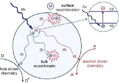
The photocatalytic activity can be reduced by the electron-hole recombination, described in
Fig.1.2, which corresponds to the conversion of the photoelectronic energy into heat.
Fig. 1.2 Processes of photoelectron-hole recombination in the semiconductor particles.
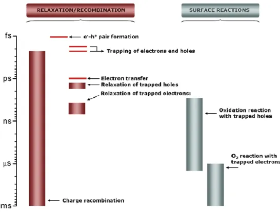
A schematic view of the time scale of the different charge carrier-related phenomena just discussed is included in Fig. 1.3.
- 10 -
Fig. 1.3 Time scales of “elemental steps” occurring in a typical photocatalytic process.
Both the above surface photoreactions can be exploited for some important environment applications as the degradation of dangerous organic compounds both in air or in water (photo-oxidation reactions) or as the hydrogen production by water splitting (photoreduction reaction). For these reasons, photocatalysis can be regarded as a new and interesting hot subject of the modern research. The increasing interest for this topic is expressed by the continuous increase of number of papers (Fig.1.4) in the last decade.
- 11 -
Fig. 1.4 Number of publications concerning photocatalysis over the years 2003- 2017( September) based on
database Scopus with keyword “photocatalysis”.
Many semiconductors have been used as photocatalysts: TiO2, ZnO, WO3, CdS and NiO can be
found among the best performing ones. Each photocatalyst is characterized by a different band gap energy and oxidizing power. The thermodynamic driving forces in photocatalytic processes are strongly dependent on the relative relationships between the conduction band (CB) and valence bande (VB) potentials of the semiconductor photocatalysts used and to the redox potentials of reversible target reactions [4, 5]. Thus, the more negative CB positions of semiconductors are beneficial for reduction reactions, while the more positive VB positions of semiconductors are favorable for oxidation reactions. The band positions (at pH=7 in aqueous solution) for some important semiconductor photocatalysts and their potential applications are listed in Fig. 1.5.
- 12 -
Fig. 1.5 Band positions and potential applications of some typical photocatalysts [4].
Titanium dioxide (TiO2) has emerged as a leading photocatalyst for environment purifications
due to its strong oxidizing power under ultraviolet irradiation, high chemical stability, low cost, and environment friendly [6-10]. However, the photo-catalytic efficiency of TiO2 nanomaterials
is still not up to the mark to meet out the practical needs under direct sunlight irradiation because the large intrinsic band gap (3.2eV) of TiO2 severely restricts its utilization of the visible light
and the fast electron-hole recombination in TiO2 often results in a low quantum yield and poor
photocatalytic activity [11-13]. To efficiently utilize abundant and green sunlight, therefore, a series of strategies, such as metal/non-metal elements doping and coupling with other functional materials have been adopted to increase the TiO2-based photocatalysts activity, by introducing an
extrinsic band gap with lower energy, suppressing electron-hole recombination rate, and increasing the surface charge carrier transfer rate of TiO2 [14-16]. A detail description of the
strategies to improve the TiO2 performances and the methodologies used in this work, will be
discussed in next chapters.
1.2 Photo-oxidation of organic contaminants in air
The photocatalytic mechanism can be successful applied in the air purification and in particular one of the most important reactions investigated is the photo-oxidation of VOCs [17-19]. Nowadays people spend most of their time (more than 90% [20]) in an indoor environment; consequently the indoor air quality (IAQ) has a significant impact on human health, comfort and productivity [21]. A long-term exposure to indoor air pollutants can be detrimental to human health and lead to sick building syndrome, building related illnesses and in extreme cases cancer [22].VOCs, nitrogen oxides (NOx), carbon monoxide (CO), and particulate matter are among the
- 13 -
main indoor air pollutants. Levels of pollutants in indoor environment can be higher than those of outdoor air due to the contribution of indoor sources such as combustion by-products, building materials, office equipment (e.g. printers and computers), and consumer products [22, 23]. Recently, photocatalyis technology has attracted great attention for removal of gaseous pollutants at low concentrations (i.e. part per billion (ppb) level), owed to its superior features compared to other methods (i.e. adsorption or ozonation) such as room temperature operation, activity towards various contaminants, and benign final products (CO2 and H2O) [21, 22, 24].
After the activation of the semiconductor particles by an opportune light radiation, the photogenerated charge carriers participate in a series of reactions with other molecules such as oxygen and water and produce highly reactive radicals (such as hydroxyl or superoxide radicals). In gas phase, mass transfer of the VOC compounds from the gas phase (i.e. air stream) to the solid phase plays an important role and greatly affects the reaction rate and removal efficiency. After the external (from bulk to exterior surface) and internal diffusions (from exterior surface to internal catalytic surface) and adsorption onto the surface, pollutant molecules come into contact with the produced reactive species and break down to lower molecular weight products and eventually to CO2, water and other by products [21,25].
The basic reaction mechanism using a photocatalyst as TiO2 can be depicted as follows [17, 18,
26]:
a) TiO2 activation ( λ ≤ 388 nm): TiO2 + hv → TiO2(e-CB- + h+VB)
b) Photo-oxidation by holes TiO2(h+VB) + H2O → TiO2 + H+OH
c) Formation of superoxide radical TiO2(e-CB) + O2 → TiO2 + O2
-d) Formation of hydrogen peroxide O2-+ H+→HO2
HO2 + HO2→H2O2+ O2
e) Formation of hydroxyl radical TiO2(e-CB) + H2O2→TiO2 + OH
+
OH-f) Photo-oxidation of VOCS VOC + O2+ OH→ H2O + CO2 + other products
Apart from their beneficial participation in oxidation and reduction reactions, electrons and holes also go, as described before, through recombination process where they neutralize one another. Moreover many parameters can influence the photoactivity as the adsorption properties of the photocatalyst, the type and the concentration of VOCs and the type and the intensity of the light source used for the irradiation.
Adsorption of pollutant onto the surface of photocatalyst is a crucial step that greatly affects the reaction rate and removal efficiency. Adsorption of challenge compounds on photocatalyst
- 14 -
brings about better contact between photocatalyst and reactant molecules, which in turn leads to higher oxidation rate. The role of adsorption step is more critical when dealing with gas streams with high humidity level (typical condition in the mechanical ventilation system of buildings) due to the competition between VOCs and water molecules for adsorption sites. Depending on the type of active site available on the surface of photocatalyst and target VOCs, different adsorption mechanisms may exist. Nimlos et al. [27] suggested that alcohols and organic acids can be adsorbed over the surface of TiO2 via both dissociative adsorption at oxygen bridging
sites and hydrogen bond to the OH groups while aldehydes can only be adsorbed via hydrogen bond to the surface OH groups. Alberici and Jardim [28] reported that the adsorption of VOCs on TiO2P25 (80% anatase, 20% rutile) follows the order: methanol > isopropanol > MEK >
acetone > toluene > i-octane, indicating higher adsorption of alcohols than aromatics over TiO2.
Consequently the type and the concentration of VOCs is a key aspect. For various classes of VOCs and broad ranges of concentration, there is general agreement that higher concentration of VOCs results in an improved reaction kinetics (until rate reaches its plateau), lower removal efficiency, and poorer mineralization of pollutants to CO2 [29-32]. The impact of higher VOCs
concentration on photo-oxidation reactions can be analyzed from different aspects: (i) the number of VOCs molecules that can be adsorbed and oxidized on photocatalyst surface increases which boosts the reaction kinetics [33]; (ii) the ratio of reactive species plus active sites to pollutant molecules decreases and consequently, more VOCs can leave the reactor without undergoing degradation [30]; (iii) high amount of by-products/intermediates generated during the reactions can reduce the mineralization and/or occupy part of the active sites, impeding the oxidation progress. The effect of pollutant concentration and type on photocatalytic degradation kinetics has been investigated by many researchers [34-37]. Jafarikojour et al. [38] observed that by increasing the inlet concentration of toluene from 20 to 100 ppm at 30% Relative Humidity (RH), the conversion decreased from 37% to ca. 27%. Similarly, Mo et al. [24] found that decomposition efficiency of toluene dropped ca. 30% by increasing toluene concentration from 1 to 4 ppm.
Palmisano et al. found that the presence of oxygen was essential for the occurrence of the
photo-oxidation of toluene while water played an important role in order to maintain the catalyst activity [36, 39]. In another study, Vildozo et al. [40] showed that increasing the inlet concentration of 2-propanol from 100 to 700 ppb significantly lowered the mineralization rate from ca. 90% to 63%. Interestingly, it was found a positive linear relationship between KOH and
photo-oxidation reaction rate constant [41, 42] that is however different towards the various organic compounds. Jeong et al. [43] obtained higher removal efficiency for toluene
(82.6-- 15 (82.6--
99.9%) compared to benzene (67.1-94.2%), and ascribed this behavior to the higher reaction rate of toluene with hydroxyl radicals in the gas phase and on TiO2P25. Considering the principles of
catalytic reactions, at low pollutant concentration (number of VOCs molecules ~ number of photocatalyst active sites), the reaction rate increases with pollutant concentration until it reaches a region (i.e. intermediate VOCs concentration) where the reaction rate becomes independent of concentration [44]. Most of the researchers believe that any further increment in the concentration of pollutant neither improves or deteriorates the reaction rate since photocatalyst is working at its maximum capacity [44-47]. On the contrary, investigations on the photo-oxidation of benzene [48] and toluene [49] showed that at higher concentration due to the deposition of refractory reaction intermediates on photocatalyst surface and loss of active sites the reaction rate dramatically drops. Similarly, Monteiro et al. [33] observed that under low light intensity, conversion and reaction rate of Perchloroethylene (PCE) firstly increases with concentration and then decreases. The noted downward trend for reaction rate was attributed to the lack of photogenerated e−-h+ and surface flooding due to an excessive PCE load.
Light is one of the main pillars of photocatalysis; therefore, light source wavelength (WL) and light intensity (I) can affect the reaction rate and removal efficiency. Theoretically, UV light with wavelength less than 380 nm can excite the electrons in the valence band of TiO2 (the most
used photocatalyst). Germicidal lamp (UVC, 254 nm) and fluorescent black-light lamp (300-400 nm) are the most utilized light sources in the photocatalytic oxidation (PCO) of indoor air pollutants. Some studies employed UV light emitting diode (wavelength usually centered at 365 nm) due to long lifetime and high efficiency. For the same photon energy distribution, i.e. light wavelength, increasing the light intensity leads to generation of a larger number of photons and consequently e−-h+ pairs. It is proposed that the impact of UV intensity on the reaction rate can be divided into two regimes: (i) a first-order regime at lowlight intensity and high VOCs concentration where e−-h+ pairs are consumed faster by chemical reactions than by recombination and (ii) a half-order regime at high light intensity and low VOCs concentration in which the rate of recombination exceeds the rate of oxidation reactions [50, 51].
In this thesis work the photo-oxidation of 2-propanol and ethanol was investigated over different TiO2-based materials under UV irradiation (UV mercury lamp, 100 W, 365 nm), the state of art
and the reaction mechanism for the degradation of these alcohols will be discussed in detail in the next chapters.
- 16 -
1.3 Photo-oxidation of organic contaminants in water
The discharge of refractory organic contaminants through wastewaters into the environment causes all over the world dangerous environmental pollution. Furthermore the gap between the clean water and its availability is expected to continue to increase with respect to growing contamination, owing to the overwhelming discharge of contaminants and pollutants into the natural water cycle. As far as the environment is concerned, the reuse and recycling of wastewater effluents is thus necessary to augment the limited fresh water supply and to offset more possible water resources in the long run [52]. During the past few decades, a variety of practical strategies have been implemented to develop viable wastewater treatment technologies [53-55]. For instance, conventionally, biological treatments were designed to effectively eliminate assorted types of contaminants from wastewater in the short term; however, these techniques also normally lead to the production of secondary pollution [56] some of which even involves the presence of health-threatening bacteria and soluble refractory organic compounds that are hard to remove [57].
Photocatalysis has been considered as one of the most appealing options for wastewater treatment, due to its great potential and high efficiency by using sunlight to remove organic pollutants and harmful bacteria with the aid of a solid photocatalyst [58, 59].
The general mechanism of photo-oxidation in water is the same described above for the photodegradation of VOCs (pag. 13, reactions a-f). The photogenerated h+ is widely considered as an oxidant for directly degrading organic contaminates, the capacity of which depends on the catalyst type and oxidation conditions [60]. To design a photocatalyst capable of utilizing safe and sustainable solar energy effectively, several critical requirements need to be satisfied. First, the semiconductor material should have a smaller band-gap to allow it to absorb solar energy across a broad range of spectrum. Simultaneously, the semiconductor should have a relatively positive enough valence band for the ample production of h+ and OH radicals [61]. Second, the catalyst should possess a particular platform/system for the efficient charge separation and transportation [62, 63]. Moreover, the semiconductor materials should have good photoelectrochemical stability in the electrochemical reactions [64].
In most cases, different types of dyes are studied as model compounds for the photocatalytic degradation of large organic molecules in water treatment. Organic dyes are often used in textile, printing, and photographic industries, but a sizable fraction of dyes is wasted in the dying process and is released into effluent water streams. In general, the presence of even low concentrations of dyes in effluent streams seriously affects the nature of water, and is difficult to be biodegraded or oxidized with the aid of chemicals.
- 17 -
Pharmaceutical and personal care products (PPCPs) have recently been considered as emerging contaminants, and are an extraordinarily diverse group of chemicals used in prescription and non-prescription drugs, human health and cosmetic care, veterinary medicine, and agricultural practice [65, 66]. Specific PPCPs may cause ecological harm, such as endocrine disruption and antimicrobial resistance, thus some of PPCPs have been classified as “priority pollutants” by both the US Environmental Protection Agency and the European Union Water Framework Directive. PPCPs have frequently been studied with respect to environmental protection because of their toxicity and non-biodegradability.
Phenolic compounds can cause various diseases, including cancer, angiocardiopathy, gastroenterology etc., even at very low concentrations, and represent a typical family of organic pollutants widely present in wastewater from petrol, coal, and other chemical industries [67-70]. Most phenolic compounds are usually difficult to be mineralized by a biodegradation method, due to the stable benzene ring and its recalcitrant nature. However, such compounds have been reported to be effectively degraded by TiO2 and other visible light-responsive photocatalysts [
71-74].
Other organic pollutants, such as benzylalcohol, methanol, benzyl amine, hydroxytyrosol, and benzene, in aqueous solutions have also been reported to be efficiently degraded by visible light induced photocatalytic processes [75-77].
The presence of inorganic impurities, such as residual ions and acids, in the water matrix has distinctive effects toward a water system’s ecological environment. Some of them are highly toxic to most of living organisms when their concentration levels are higher than a certain value. For instance, hexavalent chromium (Cr(VI)) is a carcinogenic and mutagenic pollutant, which is frequently found in wastewater, possibly stemming from pigment production, metal plating, leather tanning, etc. The visible light induced photocatalytic reduction of aqueous Cr(VI) has received much attention recently, due to its low cost and high efficiency without secondary pollution [78, 79].
The different types of microbes (bacteria, viruses, fungi, algae, plankton, etc.) present in wastewater are harmful to health and can cause various diseases [80]. Also for this type of pollutants over the past few decades, the visible light activated photocatalytic disinfection of water was intensively studied, with research focus moving from laboratory analysis to potential applications [81, 82]. For example, a dye-sensitized TiO2 thin film was used in the photocatalytic
disinfection of phytopathogenic bacteria under visible light irradiation. The inhibition rates of
Erwiniacarotovora subsp. carotovora 3, Enterobacter cloacae SM1, and E. carotovora subsp.carotovora 7 that could induce severe soft/basal rot disease in vegetable crops were higher
- 18 -
than 90%. These results indicated that the visible light-responsive dye-sensitized TiO2 thin film
had the potential for direct application to plant protection in water systems [81]. A visible light-activated palladium-modified nitrogen-doped titanium oxide (TiON/PdO) photocatalyst has been demonstrated with good visible light adsorption and a superior efficient photocatalytic disinfection effect on Fungi Fusarium graminearum macroconidia.
Fig.1.6 Photocatalytic disinfection mechanism of TiON/PdO photocatalyst on Fusarium graminearum macroconidia
under visible light irradiation [82].
The disinfection effect benefitted from the strong adsorption of the TiON/PdO photocatalyst onto the Fusarium graminearum macroconidia surface due to their opposite surface charges. The photocatalytic disinfection mechanism of the TiON/PdO photocatalyst on the Fusarium
graminearum macroconidia is displayed in Fig. 1.6, and it is attributed to their cell wall/membrane damage caused by the attack from the reactive oxygen species (ROSs), while a breakage of their cell structure was not necessary for their loss of viability [82].
In this thesis the degradation in water of some dyes, as the Methylene Blue and the Rhodamine B under visible light irradiation was investigated over TiO2-based photocatalysts, the results and
- 19 -
1.4 Photocatalytic water splitting
Hydrogen is considered as an ideal fuel for the future. It can be produced from clean and renewable energy sources and, thus, its life cycle is clean and renewable. Solar and wind are the two major sources of renewable energy and they are also the promising sources for renewable hydrogen production. However, presently, renewable energy contributes only about 5% of the commercial hydrogen production primarily via water electrolysis, while other 95% hydrogen is mainly derived from fossil fuels [83]. Renewable hydrogen production is not popular yet because the cost is still high. Photovoltaic water electrolysis may become more competitive as the cost continues to decrease with the technology advancement; however, the considerable use of small band-gap semiconducting materials may cause serious life cycle environmental impacts. Alternatively, photocatalytic water splitting using TiO2 for hydrogen production offers promising
way for clean, low-cost and environmental friendly production of hydrogen by solar energy. Concerning the thermodynamics of the reaction: 2H2O ↔ 2H2+ O2 is an extremely difficult
reaction since it is endergonic by ~ 240 kJ mol-1 [84, 85] and the dissociation of water can be obtained with reasonable equilibrium yields but with very high thermal input at high temperature. The alternative is to provide the thermodynamic energy with light, in which case we need light of ~ 500 nm wavelength. Such light is abundant on earth, but the kinetic barrier to split off the first hydrogen atom from water is much more energy demanding, needing ~ 500 kJ mol-1, or light at maximum wavelength of 250 nm. Hence water is stable at the earth’s surface such wavelengths are cut out in the stratosphere before reaching ground level. Hence it is necessary a strategy to get round the kinetic problem, thus involves the use of photocatalysis to lower that barrier [86]. In a typical process the photon energy is converted to chemical energy accompanied with a largely positive change in the Gibbs free energy through water splitting as shown in Fig. 1.7. This reaction is similar to photosynthesis by green plants because these are uphill reactions.
- 20 -
Fig. 1.7 Photosynthesis by green plants and photocatalytic water splitting as an artificial photosynthesis [88].
Therefore, photocatalytic water splitting is regarded as an artificial photosynthesis and is an attractive and challenging theme in chemistry. From the viewpoint of the Gibbs free energy change, photocatalytic water splitting is distinguished from photocatalytic degradation reactions such as photo-oxidation of organic compounds using oxygen molecules that are generally downhill reactions. The Honda-Fujishima effect of water splitting using a TiO2 electrode is
illustrated in Fig. 1.8:
Fig. 1.8 Honda-Fujishima effect-water splitting using a TiO2 photoelectrode [88].
When TiO2 is irradiated with UV light electrons and holes are generated and the photogenerated
electrons reduce water to form H2 on a Pt counter electrode while holes oxidize water to form O2
on the TiO2 electrode with some external bias by power supply or pH difference between a
catholyte and an anolyte.
The characteristic feature of water splitting using a powdered photocatalyst is the simplicity; the opportune light radiation shines the photocatalyst powders dispersed in water, and then hydrogen
- 21 -
is readily obtained. Moreover, powdered photocatalyst systems will be advantageous for large-scale application of solar water splitting because of the simplicity.
The Photocatalytic reactions proceed on semiconductor materials as schematically shown in Fig. 1.9.
Fig. 1.9 Principle of water splitting using semiconductor photocatalysts.
i). H2O + h+vb 2H+ + ½ O2
ii). 2H+ + 2 e- H2
Water molecules are reduced by the electrons to form H2 and are oxidized by the holes to form
O2 for overall water splitting. Important points in the semiconductor photocatalyst materials are
the width of the band gap and levels of the conduction and valence bands. The bottom level of the conduction band has to be more negative than the redox potential of H+/H2 (0 V vs. Normal
Hydrogen Electrode NHE), while the top level of the valence band be more positive than the redox potential of O2/H2O (1.23 V) [87, 88]. Therefore, the theoretical minimum band gap for
water splitting is 1.23 eV that corresponds to light of about 1100 nm.
Presently, the energy conversion efficiency from solar to hydrogen by TiO2 (the main
semiconductor used) is still low. The main reasons are: (1) Recombination of photo-generated electron/hole pairs: CB electrons can recombine with VB holes very quickly and release energy in the form of unproductive heat or photons; (2) Fast backward reaction: Decomposition of water into hydrogen and oxygen is an energy increasing process, thus backward reaction (recombination of hydrogen and oxygen into water) easily proceeds;
(3) Inability to utilize visible light: The band gap of TiO2 is about 3.2 eV and only UV light can
be utilized for hydrogen production. Since the UV light only accounts for about 5% of the solar radiation energy while the visible light contributes about 50%, the inability to utilize visible light limits the efficiency of solar photocatalytic hydrogen production.
- 22 -
In order to resolve the above listed problems and make solar photocatalytic hydrogen production feasible, continuous efforts have been made to promote the photocatalytic activity and enhance the visible light response.
Co-catalysts such as Pt, NiO and RuO2 are usually loaded to introduce active sites for H2
evolution because the conduction band levels of many oxide photocatalysts are not high enough to reduce water to produce H2 without co-catalytic assistance. Active sites for electron oxidation
of water are required for O2 evolution. Co-catalysts are usually unnecessary for oxide
photocatalysts because the valence band is deep enough to oxidize water to form O2. This is the
characteristic point of heterogeneous photocatalysts being different from homogeneous photocatalysts for which O2 evolution with electron oxidation of H2O is a challenging reaction.
Another approach is to apply a two-step excitation mechanism using two different photocatalysts [89] (Fig. 1.10).
Fig. 1.10 Z-Scheme for the photocatalytic water splitting [89].
This was inspired by natural photosynthesis in green plants and is called the Z-scheme. The advantages of a Z-scheme water splitting system are that a wider range of visible light is available because a change in Gibbs free energy required to drive each photocatalyst can be reduced as compared to the one-step water splitting system and that the separation of evolved H2
and O2 is possible. It is also possible to use a semiconductor that has either a water reduction or
oxidation potential for one side of the system. For example, some metal oxides (e.g., WO3 and
BiVO4) function as a good O2 evolution photocatalyst in a two-step water splitting system using
a proper redox mediator, although they are unable to reduce water [90, 91].
Sacrificial reagents are often employed to evaluate the photocatalytic activity for water splitting because overall water splitting is a tough reaction. When the photocatalytic reaction is carried out in an aqueous solution including a reducing reagent, in other words, electron donors or hole scavengers, such as alcohol and a sulfide ion, photogenerated holes irreversibly oxidize the
- 23 -
reducing reagent instead of water. It enriches electrons in a photocatalyst and an H2 evolution
reaction is enhanced. This reaction will be meaningful for realistic hydrogen production if biomass and abundant compounds in nature and industries are used as the reducing reagents [92,
93].
Organic compounds (hydrocarbons) are widely used as electron donors for photocatalytic hydrogen production as they can be oxidized by VB holes. EDTA, methanol, ethanol, lactic acid and formaldehyde have been tested and proved to be effective to enhance hydrogen production [94-96]. Nada et al. [94] carried out a qualitative investigation to study the effects of different electron donors on hydrogen production. The rankings in terms of the degree of hydrogen production enhancement capability were found to be: EDTA > methanol > ethanol > lactic acid. It should be noted that the decomposition of these hydrocarbons could also contribute to a higher hydrogen yield since hydrogen is one of their decomposed products.
In accordance, Puangpetch et al. [97] found that over mesoporous-assembled SrTiO3
photocatalyst the enhancement of the activity by adding different hole scavengers was found in the following order: MeOH > EtOH > d-glucose > 2-PrOH > Na2SO3. The use of MeOH
provided the highest photocatalytic enhancement ability (the ability to increase the photocatalytic hydrogen production activity), as compared to the other studied hole scavengers, possibly because it has the highest ability to donate electrons, to scavenge the valence band holes to preventing photo-generated charge recombination [98, 99]. In a comparison among alcohols, the photocatalytic activity tended to increase with increasing alcohol concentration. For MeOH as the hole scavenger, the hydrogen production rate significantly increased in the MeOH concentration range of 0-20 vol.%; beyond this range, it only slightly increased.
Other inorganic ions, such as S2-/SO23-, Ce4+/Ce3+ and IO-3/I- were used as sacrificial reagents
for hydrogen production [100-102].
Sayama et al. [103] reported that addition of carbonate salts could significantly enhance hydrogen and oxygen production stoichiometrically. Addition of Na2CO3 was found to be
effective for enhancement of hydrogen and oxygen production using Pt loaded TiO2 (Pt-TiO2).
Later, various semiconductor photocatalysts including TiO2, Ta2O5 and ZrO2 were tested and it
was found that the presence of Na2CO3 was very beneficial for hydrogen and oxygen production
for all the photocatalysts tested [104]. The Infrared (IR) study revealed that the surface of Pt-TiO2 catalyst was covered by many types of carbonates species, such as HCO3-, CO3•- HCO3•
and C2O62-.Therefore, photo-generated holes were consumed by reacting with carbonate species
- 24 -
In this work thesis the H2 production by photocatalytic water splitting was tested over modified
TiO2-based materials both under UV and solar light irradiation. The effect of a sacrificial agent
- 25 -
References
[1] J.M. Herrmann, Top. Catal. 34 (2005) 49-65.
[2] G. Palmisano, E. García-López, G. Marcì, V. Loddo, S. Yurdakal, V. Augugliaro,L. Palmisano, Chem. Commun. 46 (2010) 7074–7089.
[3] Y.Quab, X.DuanChem. Soc. Rev. 42 (2013) 2568-2580. [4] X. Li, J. Yu, M. Jaroniec Chem. Soc. Rev. 45(2016) 2603-2636.
[5] A. Di Paola, E. García-López, G. Marcì, L. PalmisanoJ. Hazard. Mater. 211-212 (2012) 3-69. [6] J. Chen, F. Qiu, W. Xu, S. Cao, H. Zhu, Appl. Catal. A: Gen: 495 (2015) 131-140.
[7] P. Yap, T. Lim, Appl. Catal. B: Environ. 101 (2011) 709-717.
[8] S. Oros-Ruiz, R. Zanella, B. Prado, J. Hazard. Mater. 263 (2013) 28-35. [9] C. Lin, Y. Song, L. Cao, S. Chen, J. Chin. Adv. Mater. Soc. 1 (2013) 188-199.
[10] M. Addamo, V. Augugliaro, A. Di Paola , E. García-López , V. Loddo, G. Marcì , R. Molinari , L. Palmisano , M.Schiavello, J. Phys. Chem. B108 (10) (2004) 3303–3310.
[11] L. Liu, H. Bai, J. Liu, D.D. SunJ. Hazard. Mater. 261 (2013) 214-223.
[12] J. Fang, L. Xu, Z. Zhang, Y. Yuan, S. Cao, Z. Wang, L. Yin, Y. Liao, C. Xue, ACS Appl. Mater. Interfaces, 5 (2013), 8088-8092
[13] R. Asahi, T. Morikawa, T. Ohwaki, K. Aoki, Y. Taga, Science, 293 (2001), 269-271.
[14] T. Kamegawa, S. Matsuura, H. Seto, H. Yamashita, Angew.Chem. Int. Ed. 52 (2013) 916-919.
[15] S. Hoang, S.P. Berglund, N.T. Hahn, A.J. Bard, C.B. Mullins, J. Am. Chem. Soc., 134 (2012), 3659-3662. [16] Z. Wang, C. Yang, T. Lin, H. Yin, P. Chen, D. Wan, F. Xu, F. Huang, J. Lin, X. Xie, M. Jiang, Adv. Funct.
Mater., 23 (2013), 5444-5450.
[17] A. H. Mamaghani, F.Haghighat, C.-S. Lee, Appl. Catal. B: Environ: 203 (2017) 247-269. [18] Y. Boyjoo, H. Sun , J. Liu , V. K. Pareek, S. Wang, Chem. Eng. J. 310 (2017) 537-559.
[19] M.A. Aramendıa, J.C. Colmenares, S. Lopez-Fernandez, A. Marinas , J.M. Marinas, F.J. Urbano, Catal. Today 129 (2007) 102-109.
[20] N.E. Klepeis, W.C. Nelson, W.R. Ott, J.P. Robinson, A.M. Tsang, P. Switzer, J.V.Behar, S.C. Hern, W.H. Engelmann,. Anal. Environ. Epidemiol. 11 (2001) 231–252.
[21] L. Zhong, F. Haghighat, Build. Environ. 91 (2015) 191–203. [22] S. Wang, H.M. Ang, M.O. Tade, Environ. Int. 33 (2007) 694-705.
[23] S.W. Verbruggen, J.Photochem. Photobiol. C: Photochem. Rev. 24 (2015) 64-82.
[24] J.H. Mo, Y.P. Zhang, Q.J. Xu, J.J. Lamson, R.Y. Zhao, Atmos. Environ. 43 (2009) 2229-2246. [25] K. Nakata, A. Fujishima, J. Photochem. Photobiol. C: Photochem. Rev. 13 (2012) 169-189.
[26] V. Augugliaro, M. Bellardita, V. Loddo, G. Palmisano, L. Palmisano, S.Yurdakal, J.Photochem. Photobiol. C: Photochem. Rev. 13 (2012) 224-245.
[27] M.R. Nimlos, E.J. Wolfrum, M.L. Brewer, J.A. Fennell, G. Bintner, Environ. Sci. Technol. 30 (1996) 3102-3110.
[28] R.M. Alberici, W.F. Jardim, Appl. Catal. B: Environ. 14 (1997) 55–68. [29] J. Mo, Y. Zhang, Q. Xu, R. Yang, J. Hazard. Mater. 168(2009) 276–281.
[30] F.V.S. Lopes, R.A.R. Monteiro, A.M.T. Silva, G.V. Silva, J.L. Faria, A.M. Mendes,V.J.P. Vilar, R.A.R. Boaventura, Chem. Eng. J. 204-206 (2012) 244-257.
[31] P.-A. Deveau, F. Arsac, P.-X. Thivel, C. Ferronato, F. Delpech, J.-M. Chovelon,P. Kaluzny, C. Monnet, J. Hazard. Mater.144 (2007) 692–697.
[32] A. Bouzaza, C. Vallet, A. Laplanche, J. Photochem. Photobiol. A: Chem. 177 (2006)212–217.
[33] R.A.R. Monteiro, S.M. Miranda, C. Rodrigues-Silva, J.L. Faria, A.M.T. Silva,R.A.R. Boaventura, V.J.P. Vilar, Appl. Catal. B: Environ. 165 (2015)306–315.
[34] L. Zhong, F. Haghighat, C.-S. Lee, Build. Environ. 62 (2013) 155-166. [35] D. Farhanian, F. Haghighat, Build. Environ. 72 (2014)34-43.
[36] V. Augugliaro, S. Colucci, V. Loddo, L. Marchese, G. Martra, L. Palmisano, M. Schiavello, Appl. Catal. B: Environ: 20 (1999) 15-27.
[37] A.K. Boulamanti, C.J. Philippopoulos, Atmos. Environ. 43 (2009) 3168-3174.
- 26 -
[39] G. Marcı, M. Addamo, V. Augugliaro, S. Coluccia, E. Garcıa-López , V. Loddo, G. Martra, L. Palmisano , M. Schiavello J.PhotochPhotobio A 160 (2003) 105-114.
[40] D. Vildozo, C. Ferronato, M. Sleiman, J.-M. Chovelon, Appl. Catal. B: Environ. 94 (2010) 303-310. [41] A.K. Boulamanti, C.A. Korologos, C.J. Philippopoulos, Atmos. Environ. 42 (2008) 7844–7850. [42] K.-P. Yu, G.W.M. Lee, W.-M. Huang, C. Wu, S. Yang, , Atmos. Environ. 40 (2006) 375–385. [43] J. Jeong, K. Sekiguchi, W. Lee, K. Sakamoto, J. Photochem.Photobiol. A: Chem. 169 (2005) 279-287. [44] W. Wang, Y. Ku, J. Photochem. Photobiol. A:Chem. 159 (2003) 47–59.
[45] M. Sleiman, P. Conchon, C. Ferronato, J.-M. Chovelon,Appl. Catal. B:Environ. 86 (2009) 159-165. [46] L. Cao, F.-J. Spiess, A. Huang, S.L. Suib, T.N. Obee, S.O. Hay, J.D. Freihaut, J. Phys. Chem. B 103 (1999)
2912–2917.
[47] T.N. Obee, S.O. Hay, Environ. Sci. Technol. 31 (1997) 2034-2038.
[48] H. Einaga, T. Ibusuki, S. Futamura, J. Solar Energy Eng. 126 (2004) 789-793. [49] F. Tang, X. Yang, Build. Environ. 56 (2012) 329–334.
[50] D.H. Chen, X. Ye, K. Li, Chem. Eng. Technol. 28 (2005) 95-97. [51] J.-M. Herrmann, Catal.Today 53 (1999) 115-129.
[52] J. Qu, M. Fan, Crit. Rev. Environ. Sci. Technol., 40 (2010) 519-560. [53] X. Zhou, Y. Li, Y. Zhao, RSC Adv. 30 (2014) 15620-15629.
[54] V. K. Gupta, I. Ali, T. A. Saleh, A. Nayak, S. Agarwal, RSC Adv. 2 (2012)6380-6388. [55] S. Sun, C. Li, J. Sun, S. Shi, M. Fan, Q. Zhou, J. Hazard. Mater. 161 (2009) 1052–1057.
[56] O. Ganzenko, D. Huguenot, E. D. van Hullebusch, G. Esposito and M. A. Oturan, Environ. Sci. Pollut. Res., 21 (2014) 8493-8524.
[57] S. Ray, M. Takafuj, H. Ihara, RSC Adv., 3 (2013) 23664-23672.
[58] S. Dong, J. Feng, M. Fan, Y. Pi, L. Hu, X. Han, M. Liu, J. Sun, J. SunRSC Adv. 5 (2015) 14610-14630. [59] P.A.K. Reddy, P.V.L. Reddy, E.Kwonc, K.H.Kimd, T. Akter, S.Kalagara Environ. Int. 91(2016) 94-103. [60] M. N. Chong, B. Jin, C. W. K. Chow, C. Saint, Water Res. 44 (2010) 2997-3027.
[61] E. Casbeer, V. K. Sharma, X. Z. Li, Sep. Purif. Technol.,87 (2012) 1-14. [62] Y. Qu, X. Duan, Chem. Soc. Rev., 42 (2013) 2568-2580.
[63] C. Chen, W. Ma, J. Zhao, Chem. Soc. Rev., 39 (2010)4206-4219. [64] R. Abe, J. Photochem. Photobiol., C 11 (2010) 179-209.
[65] S. T. Gadge, B. M. Bhanage, RSC Adv.(4) 2014 10367–10389.
[66] R. Molinari, F. Pirillo, V. Loddo, L .Palmisano, Catal. Today 118 (2006) 205-2113.
[67] G. Li, Y. Zhang, L. Wu, F. Wu, R. Wang, D. Zhang, J. Zhuand, H. Li, RSC Adv. 2 (2012) 4822–4828. [68] G. Mele, R. Del Sole, G. Vasapollo, E.G.-López, L. Palmisano, M.Schiavello, J. Catal 217 (2003) 334-342. [69] G. Palmisano, M. Addamo, V. Augugliaro, T. Caronna, E G.Lopez, V. Loddo, L. Palmisano, Chem.
Commun., 9 (2006) 1012–1014.
[70] M. Bellardita,H.A. ElNazer, V. Loddo, F. Parrino, A.M. Venezia, L. Palmisano, Catal. Today 284 (2017) 92-99.
[71] A. Di Paola, G. Marcı`, L. Palmisano, M. Schiavello, K. Uosaki, S. Ikeda, B. Ohtani, J. Phys. Chem. B 106 (2002) 637-645.
[72] A. Di Paola, E.G. López , S. Ikeda, G. Marcì, B. Ohtani, L. Palmisano, Catal. Today 75 (2002) 87-93. [73] J. Sheng, X. Li ,Y. Xu, ACS Catal. 4 (2014) 732–737.
[74] Y. Chen, S. Liang, L. Wen, W. Wu, R. Yuan, X. Wang andL. Wu, Phys. Chem. Chem. Phys., 15 (2013) 12742-12747,
[75] S. Higashimoto, R. Shirai, Y. Osano, M. Azuma, H. Ohue, Y. Sakata, H. Kobayashi, J. Catal.311 (2014) 137–143.
[76] R. M. Mohamed, E. Aazam, Desalin. Water Treat., 51 (2013) 6082-6090.
[77] A. A. Ismail, L. Robben, D. W. Bahnemann, ChemPhysChem, 12 (2011) 982-991.
[78] L. Wang, X. Li, W. Teng, Q. Zhao, Y. Shi, R. Yue, Y. Chen, J. Hazard. Mater. 244–245 (2013) 681-688. [79] J. Yang, J. Dai, J. Li, Environ. Sci. Pollut. Res. 20 (2012) 2435-2447.
[80] H. Chen, X. Zheng, Y. Chen, H. Mu, RSC Adv., 3 (2013)9835-9842.
[81] K. S. Yao, D. Y. Wang, C. Y. Chang, K. W. Weng, L. Y. Yang, S. J. Lee, T. C. Cheng, C. C. Hwang, Surf. Coat. Technol.,202 (2007) 1329-1332.
[82] J. Zhang, Y. Liu, Q. Li, X. Zhang, J. K. Shang, ACS Appl. Mater. Interfaces5 (2013) 10953-10959. [83] M. Ni, M.K.H. Leung, D.Y.C. Leung, K. Sumathy, Renew. Sust. Energ. Rev. 11 (2007) 401-425.
- 27 -
[84] M. Bowker, Catal. Lett. 142 (2012) 923-929. [85] M Bowker, Green Chem. 13 (2011) 2235-2246.
[86] M. Bowker, H. Bahruji, J. Kennedy, W. Jones, G. Hartley, C. Morton, Catal Lett 145 (2015) 214–219. [87] T.Hisatomi, K.Takanabe, K. Domen, Catal. Lett. (2015) 145, 95-108.
[88] A. Kudo, Y.Miseki, Chem. Soc. Rev. 38 (2009), 253-278. [89] K. Maeda, K.Domen, J. Phys. Chem. Lett. 1 (2010) 2655–2661.
[90] K. Sayama, K. Mukasa, R. Abe, Y. Abe, H.Arakawa, Chem. Commun (2001) 2416-2417. [91] H.Kato,M.Hori, R.Konta, Y.Shimodaira,A.Kudo, Chem. Lett. 33 (2004), 1348-1349. [92] T. Kawai, T. Sakata, Nature (1980) 286, 474-476.
[93] GR. Bamwenda, S. Tsubota, T.Nakamura, M. Haruta, J Photochem.Photobiol. A: Chem 89(2) (1995) 177– 89.
[94] AA. Nada, MH. Barakat, HA. Hamed, NR. Mohamed, TN.Veziroglu, Int J Hydrogen Energy 30(7) (2005) 687-691.
[95] SQ Peng, YX Li, FY Jiang, GX Lu, SB Li,ChemPhys Lett 398 (2004), 1–3, 235-239.
[96] T Kida, GQ Guan, N Yamada, T Ma, K Kimura, A.Yoshida,Int J Hydrogen Energy 29(3) (2004)269-274. [97] T. Puangpetch, T. Sreethawong, S. Yoshikawa, S. Chavadej, J. Mol. Catal. A: Chem. 312 (2009) 97-106. [98] T. Sreethawong, T. Puangpetch, S. Chavadej, S. Yoshikawa, J. Power Sources 165 (2007) 861-869. [99] A. Hameed, M.A. Gondal, J. Mol. Catal. A: Chem. 233 (2005) 35-41.
[100] A.Koca, M.Sahin Int J of Hydrogen Energy 27 (2002) 363–367. [101] GR Bamwenda, H.Arakawa, Sol Energy Mater Sol Cells 70 (2001) 1-14. [102] R. Abe, K.Sayama, K.Domen, H.Arakawa. Chem Phys Lett 344 (2001) 339–44.
[103] K Sayama, K Yase, H Arakawa, K Asakura, A Tanaka, K Domen, et al. J PhotochemPhotobiol A: Chem114 (1998) 125-135.
- 28 -
Chapter 2: TiO
2-based materials
2.1 Titanium dioxide
Titanium dioxide (TiO2) has attracted considerable attention for various applications such as
pigments, photocatalysis, dye-sensitized solar cells, sensor devices, cosmetics and protective coatings. In particular, TiO2 is the most studied photocatalyst because of its high efficiency,
non-toxicity, chemical and biological stability, and low cost.
There are four common crystalline phases of TiO2: anatase, rutile, brookite, and TiO2(B) [1].
Fig. 2.1 Crystalline structures of TiO2 in different phases: (a) anatase, (b) rutile, (c) brookite, and (d) TiO2(B) [1].
As shown in Fig. 2.1, all of these phases consist of TiO6 octahedra, but differ in both the
distortion of their octahedra units and the manner in which they share edges and corners [2]. For anatase, four of the eight neighbors of each octahedral share edges; the subsequent others share corners. The corner-sharing octahedron forms the (0 0 1) planes and their edges connect with the plane of the octahedron below [3]. In rutile, the octahedral structure shares two edges and eight corners. The corner-sharing is along the [1 1 0] direction and stacks with their long axis alternation by 90° [3].The Ti–O bond lengths are 1.937 and 1.966 Ǻ for anatase and 1.946 and
- 29 -
1.983 Ǻ for rutile in the equatorial and axial directions, respectively [3]. The different structural arrangements result in different space groups. For brookite, both corners and edges are connected [4, 5]. TiO2(B) is mainly derived from the layered titanates. The structure of TiO2(B) is
composed of corrugated sheets consisting of both edges and corners shared by the TiO6
octahedra [6].
Rutile is the stable phase at high temperatures, but anatase and brookite are common in fine grained (nanoscale) natural and synthetic samples. On heating concomitant with coarsening, the following transformations are all seen: anatase to brookite to rutile, brookite to anatase to rutile, anatase to rutile, and brookite to rutile. These transformation sequences are very closely balanced in energetic as a function of particle size. The surface enthalpies of the three polymorphs are sufficiently different that crossover in thermodynamic stability can occur under conditions that preclude coarsening, with anatase and/or brookite stable at small particle size [7]. The electronic structure of TiO2 has been extensively studied using ab initio methodology [8]. Considering
rutile and anatase phases, their differences in lattice structures cause different densities and electronic band structures, leading to different band gaps. For bulk materials, the band gap for anatase TiO2 is approximately 3.20 eV (corresponding to 384 nm) and the band gap of rutile is
3.02 eV (corresponding to 410 nm). The electronic structure of both phases of TiO2 can be
understood with molecular band theory [8]. At the top of the valence band maximum (VBM) is the nonbonding O p orbital (out of the Ti3O cluster plane), where at the bottom of the conduction
band maximum (CBM) are the nonbonding Ti dxy states. For rutile, the Ti dxy orbitals at CBM
are relatively isolated, while the t2g orbitals of the CBM provide the metal-metal interaction with
a smaller distance of 2.96 Å. The conductive band width of anatase is thus smaller than that of rutile, resulting in a slightly wider band gap of 3.2 eV as compared to 3.0 eV for rutile [9, 10]. Theoretical and experimental works report band gap values for brookite both smaller and larger than that of anatase. Experimental band gap energies ranging from 3.1 to 3.4 eV have been reported for brookite, but there is disagreement on whether the optical response is attributable to direct or indirect transitions [4]. The band gap was usually determined by diffuse reflectance measurements, from the tangent lines to the plots of the modified Kubelka-Munk function, [F(R’∞)hν]1/2, versus the energy of the exciting light [11] considering brookite as an indirect
semiconductor. Direct band gap values have been also obtained [12-14].
The precise value of Eg is currently unknown since the experimental results often refer to
samples not well crystallized.
The flat band potential, (EFB), of a semiconductor is a fundamental property for the
- 30 -
can be assumed that the positions of the flat band potential and the quasi-Fermi level (*Ef) are
the same and very close to the lower edge of the conduction band [15]. Di Paola et al. [16] determined the flat band potentials of anatase, brookite, and rutile by a slurry method [17], measuring the photovoltage of the corresponding suspensions in the presence of methyl viologen dichloride as a function of pH. As shown in Fig. 2.2, the values obtained at pH 7 were -0.45 V for anatase, -0.46 V for brookite, and -0.37 V for rutile.
Fig. 2.2 Electrochemical potentials of the band edges of anatase, brookite, and rutile at pH = 7 [16].
The few experimental values of flat band potential of brookite reported in literature and the uncertainty on its band gap do not allow to exactly locate the position of the conduction and valence band edges of the three oxides of titanium. Anyway, the most probable hypothesis is that the flat band of brookite is shifted negatively with respect to that of anatase.
The electronic band structure influences the photon absorption process and redox reaction ability for photocatalysis. As explained in the chapter one, only photons with energy pertaining to that of the TiO2 band gap can be absorbed. Upon exposure to the required photon energy, electrons in
the valence band will be excited to the conduction band while leaving positively charged holes in the valence band. An electron-hole pair will therefore be generated, as expressed in followed equation typical for the TiO2-based materials:
TiO2 + hν → e−+ h+ (1)
h+ +TiIII O−H → TiIV O−H+ (2) e−+ TiIVO−H → TiIV O−H− (3) O2− + TiIV O−H+→ TiIV O−H + O2 (4)
These charge carriers have three possible fates: (i) be captured and trapped by defect sites within or on the surface of the material, (ii) recombine and release energy in the form of heat or light, or (iii) migrate to the surface and generate radical species in equations (2)-(4) [18]. Electron paramagnetic resonance studies have found that electrons are trapped by Ti atoms, forming two
- 31 -
TiIII centers, while holes are trapped as O centered radicals covalently linked to surface Ti atoms and localized differently at defect sites in TiO2 nanoparticles [19]. Consequently, the reactions
(1) and (2) are known as ‘deactivation processes’ since these electron-hole pairs do not play any part in photocatalysis. Therefore, the photocatalytic efficiency is determined by inhibiting process (1) and (2), while enhancing process (3) at optimized conditions.
As described before, the photocatalytic efficiency of TiO2 photocatalystis is still low [20].
A variety of effective strategies have been adopted to enhance the photocatalytic efficiency of TiO2 materials. In general, they can be summarized as either morphological change, such as
tailoring the surface complexity, crystalline phase, pore and size of these materials, or as chemical modification by incorporation of additional components in the TiO2 structure.
2.2 Strategy to enhance the TiO2 photoefficiency: Chemical modifications
It is possible increase the photocatalytic activity of TiO2 photocatalyst towards the develop of
supported TiO2 materials to decrease their aggregation, designing the TiO2 photocatalytic
performance in the visible light range by doping with metallic or non-metallic elements or synthesizing TiO2-based composites.
Because of relatively small size (5-50 nm), TiO2 is subjected to rapidly aggregation in a
suspension, considerably decreasing its effective surface area and catalytic efficiency. Another main limitation of pure TiO2 is very poor adsorptive power, especially for non-polar dyes and
organic pollutants due to its intrinsic surface characteristics, which restrict the photocatalytic oxidation reaction [21]. Therefore, photocatalysts in the form of nanoparticles, single atoms, molecules, and clusters should be anchored on various bulky support materials such as activated carbon [22], clay [23] and silica [24, 25] due to the small size of powder, leaking problems in aqueous media, and difficult handling in practical engineering applications [26]. Clearly, the support materials affect not only the adsorption of organic substrates, due to their nature, but also the crystallinity of TiO2 photocatalyst [26].
In order to fully utilize the solar energy, considerable endeavor has been devoted to enhancing the TiO2 photocatalytic performance in the visible light range [27, 28]. Doping with metallic or
non-metallic elements has been widely used to improve photoactivity under visible light irradiation, in which non-metal or metal ions are either incorporated into the bulk of TiO2 (Figs 2.3, 2.4) [29, 30].
- 32 -
Fig. 2.3 Scheme of modified TiO2:(A) with transition metal oxide clusters, (B) with surface non-metal dopants and
(C) bulk metal/non-metal dopants [30].
Fig. 2.4 Schematic representation of the possible point defects present at the TiO2 lattice [31]
Non-metal doping is far more successful than metal decorating because it can create a mid-gap state acting as an electron donoror acceptor in the band gap of TiO2, which introduces lower
band gap and shifts the optical absorption of TiO2 into the visible-light region [31, 32]. In
particular, carbon doping exhibits greatly potential advantages over other types of non-metal doping because of the several outstanding properties [33, 34]. For instance, carbon presents
- 33 -
metallic conductivity as one of the many possible electronic materials [35]. It has a large electron-storage capacity and can accept the photon-excited electrons to improve the separation of photo-generated carries [36]. Moreover, carbon absorbs a wide range of visible light absorption and show a high adsorption of organic pollutants, facilitating the interface reaction of photocatalysis [33, 34]. In the process of carbon doping, the C elements implied permeating to the lattice of TiO2 substituting a lattice O atom and form O-Ti-C bond, which produces a hybrid
orbital just above the valence band of TiO2 resulting in an enhanced visible light absorbance
[37].
N-doped TiO2 seems to be promising dopant because of its comparable atomic size with oxygen,
small ionization energy and high stability [38-40]. In the process of nitrogen doping, the N element is suggested permeating to the lattice of TiO2 substituting a lattice oxygen atom and
form nitride (Ti-N) or oxynitride (O-Ti-N) arrangements, introducing energy states above the valence band of titania due to N 2p, mixing of the N 2p with O 2p states, or introducing a new mid-gap state created by N incorporation [38-40].
Electron-hole charge separation is a key factor in achieving high quantum photocatalytic efficiency [41]. Noble metal particles such as Ag, Au, Pd and Pt have been introduced in TiO2
materials to increase the lifetime of e−/h+ pairs due to their plasmon resonance produced by the collective oscillations of surface electrons (Fig. 2.5) [42].
Fig. 2.5 Surface Plasmon Resonance effect on noble metal particles/TiO2 system.
Here, the metal nanoparticle acts as a mediator in storing and shuttling photo-generated electrons from TiO2 surface to an acceptor [43]. Decorating noble metal on TiO2 photocatalyst has some
![Fig. 1.7 Photosynthesis by green plants and photocatalytic water splitting as an artificial photosynthesis [ 88 ]](https://thumb-eu.123doks.com/thumbv2/123dokorg/4533238.35409/21.892.253.667.109.418/photosynthesis-green-plants-photocatalytic-water-splitting-artificial-photosynthesis.webp)
![Fig. 2.4 Schematic representation of the possible point defects present at the TiO 2 lattice [ 31 ]](https://thumb-eu.123doks.com/thumbv2/123dokorg/4533238.35409/33.892.238.676.454.916/fig-schematic-representation-possible-point-defects-present-lattice.webp)