Scuola di Ingegneria Industriale e dell’Informazione
Corso di Laurea Magistrale in Ingegneria Biomedica
3D-Printed Microfluidic Oxygen Sensor System
Relatore: Prof. Marco Carminati
Co-relatore: Prof. Michael Johannes Vellekoop
Tesi di Laurea Magistrale di
Ali Kasiri Habibabadi
Matricola: 897432
Anno Accademico 2019-2020
Milan, Italy
Systems
Laboratory of physical Chemosensors and Microfluidics
Supervisor: Prof. Michael Johannes Vellekoop
Assistant: Camilla Konermann
Guest researcher: Ali Kasiri Habibabadi
Oct 2019- Jul 2020
Bremen, Germany
i Acknowledgement
I would like to thank the following people for helping with this Master thesis: Prof. Michael Johannes Vellekoop, representatives from Institution for Microsensor, Actuator and System(IMSAS), Bremen, Germany , for his enthusiasm for this master thesis and his practical suggestions.
My supervisor, Prof. Marco Carminati from Politecnico di Milano, for his support in corona virus situation and his encouragements to continue my work.
Camilla Konermann who took the time to complete my questionnaire and who is responsible for training me and guide me in this duration effectively.
Also, I would like thank my parents and my siblings for their supports and encouragements so far from me.
Finally, I would particularly like to thank my girlfriend for her patience, unlimited love and her unconditional supports in hard and critical times.
ii Abstract
This master thesis was carried out in the Institute for Microsensor, Actuator and System (IMSAS), Bremen, Germany. The entire designing and manufacturing processes have been done in the laboratory of physical chemosensors and microfluidics in IMSAS.
We present the 3D printed microfluidic channel oxygen sensor for monitoring and measuring the oxygen concentration in liquids and special cells. This mentioned thesis is a part of a project that its main aim is skin wound healing as the oxygen is playing a key role in changing the metabolism of cells. So by measuring the oxygen concentration in cells that are responsible for the regeneration of injured skin, we can speed up the procedure of skin healing as short as we can. However, in this master thesis, we have used normal water as a sample to measure oxygen concentration.
It is the first time that all parts of this sensor have been manufactured through 3D printed technology. Before that majority of them had been fabricating by traditional techniques such as; deposition, lithography, etc. so not only we can save our time, but also we can promote the precision rate and efficiency. By the way, there are some disadvantages and challenges to this technique such as; limitation of material selecting and probably of samples leakage after fabrication that we have mentioned in details in further chapters.
This sensor is an optic one that works based on photo-luminance phenomenon. For this, we place four sensing spots (fluorescent film) that are glued under the glass where is placed on top of two microfluidic channels. The sensing films are made with fluorescence material (the Platinum (II)-tetrakis-pentafluorphenyl-porphyrin (PtTFPP)).
This sensor is an integrated system that has several parts. The optical part that it is included the LEDs and sensing film, the readout part where the Raspberry Pi camera evaluates the intensity of emitted light from sensing spots by taking pictures, the controlling part where the temperature sensor and the heater are patterned on top of the glass to control the heater and the sample temperature and flowing current in LEDs. The whole fabrication process of glass and metallization of temperature sensors and heater on top of the glass is done in a cleanroom.
The whole work mechanism of this sensor is, the sensing spots will be excited by LEDs excitation that cause release photons. The photons while losing energy, they are emitting light. By increasing the oxygen concentration; the intensity emitted light from sensing spots will be decreased.
iii Sommario
Questo lavoro di tesi è stato svolto presso l’Institute for Microsensor, Actuator and System (IMSAS) di Bremen, Germania. L'intero processo di progettazione e produzione è stato fatto nel laboratorio di sensori chemo-fisici e microfluidici presso IMSAS.
Presentiamo il sensore di ossigeno a canale microfluidico stampato in 3D per il monitoraggio e la misurazione della concentrazione di ossigeno nei liquidi e nelle celle speciali. La tesi di cui sopra fa parte di un progetto che ha come obiettivo principale la guarigione delle ferite cutanee, poiché l'ossigeno gioca un ruolo chiave nel modificare il metabolismo delle cellule. Così, misurando la concentrazione di ossigeno nelle cellule che sono responsabili della rigenerazione della pelle ferita, possiamo accelerare la procedura di guarigione della pelle il più breve possibile. Tuttavia, in questa tesi di laurea, abbiamo usato l'acqua normale come campione per misurare la concentrazione di ossigeno.
È la prima volta che tutte le parti di questo sensore sono state prodotte con la tecnologia stampata in 3D. In precedenza, la maggior parte di esse era stata fabbricata con tecniche tradizionali come la deposizione, la litografia, ecc. così non solo possiamo risparmiare il nostro tempo, ma possiamo anche promuovere il tasso di precisione e l'efficienza. In particolare ci sono alcuni svantaggi e sfide a questa tecnica come; limitazione della selezione del materiale e probabilmente della perdita di campioni dopo la fabbricazione che abbiamo menzionato in dettaglio in ulteriori capitoli.
Questo sensore è un sensore ottico che funziona sulla base del fenomeno della fotoluminescenza. Per questo, mettiamo quattro punti di rilevamento (pellicola fluorescente) che vengono incollati sotto il vetro dove viene posto sopra due canali microfluidici. Le pellicole di rilevamento sono realizzate con materiale fluorescente (il Platinum (II)-tetrakis-pentafluorphenyl-porfyrin (PtTFPP)). Questo sensore è un sistema integrato che ha diverse parti. La parte ottica che comprende i LED e la pellicola di rilevamento, la parte di lettura dove la telecamera Raspberry Pi valuta l'intensità della luce emessa dai punti di rilevamento scattando foto, la parte di controllo dove il sensore di temperatura e il riscaldatore sono modellati sulla parte superiore del vetro per controllare il riscaldatore e la temperatura del campione e la corrente fluente nei LED. L'intero processo di fabbricazione del vetro e la metallizzazione dei sensori di temperatura e del riscaldatore sopra il vetro è fatto in una camera pulita.
Il principio di funzionamento è il seguente: i punti di rilevamento saranno eccitati dall'eccitazione dei LED che causano il rilascio di fotoni. I fotoni, mentre perdono energia, emettono luce. Aumentando la concentrazione di ossigeno, l'intensità della luce emessa dai punti di rilevamento sarà ridotta.
iv
CONTENTS
1 INTRODUCTION ... 1
1.1 The anatomy and physiology of the skin ... 2
1.1.1 The population of cells in skin ... 3
1.1.2 Repair ... 4
1.1.3 The relation between oxygen’s role and skin wound healing ... 6
1.2 Microfluidic devices ... 6
1.3 Review of some microfluidic sensor’s structures ... 9
1.3.1 Microfluidic Oxygen Imaging using Integrated Optical Sensor Layers and a Color Camera ... 9
1.3.2 Microfluidic oxygen sensor system as a tool to monitor the metabolism of mammalian cells ...10
1.3.3 Microfluidic oxygen sensor based on silica gels for long-term experiment ...11
1.3.4 PDMS-free microfluidic cell culture with integrated gas supply through a porous membrane of anodized aluminum oxide ...13
1.3.5 Spatially monitoring oxygen level in 3D micro-fabricated cell culture systems using optical oxygen sensing beads 14 1.4 Review of chip fabrication and film fabrication ...15
1.4.1 Film Fabrication ...16
2 THE 3D PRINTED MICROFLUIDIC DEVICES ... 18
2.1 Materials for 3D-printed microfluidics ...19
2.1.1 Fabrication of molds for PDMS-based microfluidics ...21
2.2 3D printing technologies...21
2.2.1 Stereolithography ...21
2.2.2 Photomelting ...23
2.2.3 Inkjet-based 3D Printing ...24
2.3 The advantages and disadvantages of 3D printed Microfluidic devices ...25
2.3.1 Benefits of 3D printed Microfluidic devices...25
2.3.2 Limitation of 3D Printed Microfluidics ...26
3 3D-PRINTED MICROFLUIDIC OXYGEN CONCENTRATION RATE SENSOR ... 28
3.1 Sensor Layout and chip design...28
3.1.1 The chip ...29
v
3.1.3 Challenges of design ...30
3.2 The mechanism of oxygen fluorescent sensor ...31
4 THE ASSEMBLY OF THE SETUP AND ITS READING OUT MECHANISM ... 38
4.1 The reading out mechanism and sensing concept...38
5 READ-OUT AND TEMPERATURE CONTROL ELECTRONIC CIRCUITS ... 40
5.1 Excitation LED and electronic circuit ...40
6 TEMPERATURE SENSOR AND HEATER DESIGN ... 42
6.1 Resistive temperature detectors (RTD) ...42
6.2 Thermistors ...42
6.3 Wheatstone bridge circuits ...43
6.3.1 Wheatstone bridges output stages ...45
6.3.2 Resistance-to-voltage conversion: Wheatstone bridge and INA ...45
6.3.3 Resistance-to-voltage conversion: Floating Current Source ...46
6.4 Design of temperature sensor and heater in thesis ...47
7 ELECTRONICS FOR THE READOUT AND FILTERING OF SIGNALS FROM RADIATION DETECTORS... 51
7.1 Pre-amplifier ...51
7.2 Amplification/filtering ...52
7.3 The timing circuit ...52
7.4 Electronic circuit of Temperature control ...53
7.4.1 The electronic circuit of temperature control (2) ...54
7.5 Read-out of the phase shift ...55
7.6 I-to-V amplifiers ...57
8 RESULTS ... 60
8.1 Calibration ...60
8.1.1 Characterization of temperature sensor ...60
8.1.2 Calibration of intensity ...63
vi
9.1 Create picture ...66
10 CONCLUSIONS ... 71
10.1 Gaol and main tasks ...71
10.2 Design and manufacturing procedure ...71
10.3 Outlook ...72
vii
FIGURES
FIGURE 1-1) THE STRUCTURE OF SKIN (RAIMONDI) ... 2
FIGURE 1-2) THE KEY FACTORS OF SKIN ... 3
FIGURE1-3) THE CELLS POPULATION (RAIMONDI) ... 4
FIGURE
1-4) THE PROCEDURE OF EPIDERMAL CROSS-WALK (RAIMONDI) ... 4FIGURE
1-5) SEQUENTIAL PRESENTATION OF THE STEPS INVOLVED IN TISSUE REPAIR (ANA CRISTINA DE OLIVEIRA GONZALEZ) ... 5FIGURE
1-6) SCHEMATIC OF MICROFLUIDIC STRUCTURE FOR ANALYSIS OF SINGLE CELL INTRACELLULAR MODEL (VE´ RONIQUE LECAULT, 2012) ... 7FIGURE
1-7) SCHEMATICS OF THE DROPLET CONTROL SYSTEM (MEASUREMENT CIRCUIT AND CIRCUIT OF DMF DEVICE) (SHIH, 2010) ... 8FIGURE
1-8) MICROFLUIDIC OXYGEN SENSOR CHIP; A) PHOTO OF STRUCTURE IN CROSS SECTION OF THE CHIP B) PHOTO OF THE ACTUAL CELL-CHIP DEVICE WITH TWO DIVIDED MICROFLUIDIC CHANNELS AND THREE O2-SENSITIVE CELL CULTIVATION CHAMBERS WHERE ARE POSITIONED ON EACH CHANNEL (BIRGIT UNGERBÖCK). ... 9FIGURE
1-9) THE STRUCTURE OF THE MICROFLUIDIC CHIP TO MONITOR THE OXYGEN CONSUMPTION RATE OF CULTIVATED CELLS THROUGH MEASURING THE CONCENTRATION OF DISSOLVED OXYGEN (FRANK BUNGEA, 2019). ... 10FIGURE
1-10) SCHEMATIC STRUCTURE OF THE MICROFLUIDIC CHIP FOR MEASURING THE CONCENTRATION OF DISSOLVED OXYGEN IN THE MEASUREMENT CHANNEL (HEIGHT: 200ΜM) WITH AN INTEGRATED TEMPERATURE SENSOR AND HEATER THAT MADE OUT OF PLATINUM (FRANK BUNGE, MICROFLUIDIC OXYGEN SENSOR BASED ON SILICA GELS FOR LONHTERM EXPERIMENTS, 2018). ... 12FIGURE
1-11) PHOTO OF THE MICROFLUIDIC CHANNEL CHIP LEFT: BOTTOM VIEW WITH INLETS AND THE ELECTRICAL HEATING AND TEMPERATURE SENSING ELEMENT BASED ON THE CHANGE OF THE RESISTIVITY. RIGHT: TOP VIEW WITH THE MICROFLUIDIC CHANNELS AND THE PHOSPHORESCENT SPOTS. ... 12FIGURE
1-12) STRUCTURE OF THE MICROFLUIDIC CHIP TO CULTIVATE MAMMALIAN CELLS (VELLEKOOP, 2018) ... 13FIGURE
1-13) GAP BETWEEN AIR AND LIQUID THAT HAS BEEN PRESSED OUT OF A PORE OF AAO (VELLEKOOP, 2018) ... 14FIGURE
1-14) SCHEMATIC DRAWING OF THE COMPOSITION AND STRUCTURE OF OXYGEN SENSING BEADS AND APPLICATION OF OXYGEN SENSING BEADS TO PDMS AND COLLAGEN BASED 3D INTESTINAL EPITHELIAL CACO-2 CULTURE SYSTEM FOR REAL TIME MAPPING OF OXYGEN LEVEL DISTRIBUTION ON THE CULTURE SURFACE (LIN WANG M. A., 2013). ... 15viii
FIGURE
1-15) SCHEMATIC OF FABRICATION OF THE MICROFLUIDIC CHIP (FRANK BUNGE, µRESPIROMETER TO DETERMINE THE OXYGEN CONSUMPTION RATE OF MAMMALIAN CELLS IN MICROFLUIDIC CULTURE,2017) ... 16
FIGURE
1-16) FABRICATION OF THE OXYGEN SENSITIVE FILM BASED ON TETRAETHYL ORTHOSILICATE (TEOS) (FRANK BUNGE, MICROFLUIDIC OXYGEN SENSOR BASED ON SILICA GELS FOR LONHTERM EXPERIMENTS, 2018) ... 17FIGURE
2-1) 3D PRINTING PROCESS (YONG HE Y. W.-Z.-J., 2016) ... 19FIGURE
2-2) THE FUNDAMENTAL OF (A) SLA AND (B) DLP (TAO HAN, APRIL 2019) ... 22FIGURE
2-3) THE FUNDAMENTAL OF SLS/SLM (YONG HE Y. W.-Z.-J., 2016) ... 24FIGURE
2-4) THE FUNDAMENTAL OF INKJET-BASED 3DP. (A) 3DP-P; (B) 3DP-LR (YONG HE Y. W.-Z.-J., 2016)... 25FIGURE
3-1) THE 3D PRINTED CHIP AND ITS DIFFERENT SECTIONS ... 29FIGURE
3-2) THE 3D-PRINTED CHIP WITHOUT GLASS ... 30FIGURE
3-3) THE 3D-PRINTED CHIP-PROTOTYPE ... 30FIGURE
3-4) ELECTROMAGNETIC RADIATION AND ITS MATTER (ALIVERTI, TECHNOLOGIES FOR SENSORS AND CLINICAL INTRUMENTATION, 2019) ... 32FIGURE
3-5) FAMILY OF LUMINESCENCE ... 33FIGURE
3-6) LUMINESCENCE = EMISSION OF PHOTONS FROM ELECTRONICALLY EXCITED STATES (ALIVERTI, TECHNOLOGIES FOR SENSORS AND CLINICAL INTRUMENTATION, 2019) ... 34FIGURE
3-7) SINGLET EXCITED STATE FIGURE
3-8) TRIPLET EXCITED STATE ... 35FIGURE
3-9) JABLONSKI ENERGY DIAGRAM (ALIVERTI, TECHNOLOGIES FOR SENSORS AND CLINICAL INTRUMENTATION, 2019) ... 35FIGURE
3-10) THE DIAGRAMS OF INTENSITY AND ENERGY IN THREE TYPES OF ELECTROMAGNETIC RADIATION PHENOMENON (ALIVERTI, TECHNOLOGIES FOR SENSORS AND CLINICAL INTRUMENTATION, 2019) ... 36FIGURE
4-1) THE ENTIRE PHOTO OF ASSEMBLY OF THE OXYGEN SENSOR SYSTEM (FRANK BUNGEA, 2019) ... 38FIGURE
4-2) THE AUTODESK INVERTOR IMAGE OF WHOLE PART OF 3D PRINTED MICROFLUIDIC CHANNEL OXYGEN SENSOR SYSTEM. ... 39ix
FIGURE
5-1) SCHEMATIC OF INTENSITY READ-OUT CIRCUIT (JÄGER, 2019) ... 40FIGURE
5-2) SCHEMATIC OF INTENSITY READ-OUT CIRCUIT (BUNGE M. F., 2018) ... 41FIGURE
6-1) COMPARISON NTC-PTC THERMISTORS / RTD (ALIVERTI, LECTURE 7, CONDITIONING OF RESISTIVE SENSORS) ... 43FIGURE
6-2) WHEATSTONE BRIDGE CIRCUITS “DEFLECTION” MODE (ALIVERTI, LECTURE 7, CONDITIONING OF RESISTIVE SENSORS) ... 44FIGURE
6-3) WHEATSTONE BRIDGES OUTPUT STAGES (ALIVERTI, LECTURE 7, CONDITIONING OF RESISTIVE SENSORS) ... 45FIGURE
6-4) RESISTANCE-TO-VOLTAGE CONVERSIONS: WHEATSTONE BRIDGE AND INA (ALIVERTI, LECTURE 7, CONDITIONING OF RESISTIVE SENSORS) ... 46FIGURE
6-5) RESISTANCE-TO-VOLTAGE CONVERSION: FLOATING CURRENT SOURCE (ALIVERTI, LECTURE 7, CONDITIONING OF RESISTIVE SENSORS) ... 47FIGURE
6-6) MASK TEMPLATE, RED: HEATER TRAIL, YELLOW: TEMPERATURE SENSOR, BLUE: SENSITIVE SPOTS ... 48FIGURE
7-1) MEASUREMENT OF THE CHARGE AND/OR OF THE TIME OF OCCURRENCE, MEASUREMENT OF THE ENERGY RELEASED BY THE RADIATION, MEASUREMENT OF THE ARRIVAL TIME OF THE EVENT (FIORINI, 2019). ... 51FIGURE
7-2) THE SCHEMATIC OF INTERNAL PRE-AMPLIFIER CIRCUIT (FIORINI, 2019)... 52FIGURE
7-3) TIMING TECHNIQUES (FIORINI, 2019) ... 52FIGURE
7-4) CROSSOVER TIMING (FIORINI, 2019) ... 53FIGURE
7-5) TEMPERATURE READ-OUT CIRCUIT (JÄGER, 2019). ... 54FIGURE
7-6) TEMPERATURE READ-OUT CIRCUIT (BUNGE M. F., 2018) ... 55FIGURE
7-7) ELECTRICAL SYSTEM FOR THE READ-OUT OF THE PHASE SHIFT (BUNGE, 2018)... 56FIGURE
7-8) ELECTRICAL SIGNALS OF THE EXCITATION LED, OF THE PHOTODIODE AND OF THE SCHMITT-TRIGGER AND THE RESULTING (BUNGE, 2018) ... 57FIGURE
7-9) LOGARETMIC AMPLIFIER ... 58x
FIGURE
7-11) TRANSIMPEDANCE AMPLIFIER (TIA)... 59 FIGURE
7-12) LOGARITHMIC AMPLIFIER ... 59 FIGURE
8-1) OBTAINED RESISTANCE OF TEMPERATURE SENSOR AT DIFFERENT TEMPERATURES (JÄGER,2019) ... 62
FIGURE
8-2) CHARACTERIZATION OF VOLTAGE AS A FUNCTION OF THE RESISTANCE (JÄGER, 2019) ... 63 FIGURE
8-3) COMPARISON OF OXYGEN CONCENTRATION OVER TIME, SAMPLES WITH CELLS AND WITHOUT CELLS ARE MEASURED (C. KONERMANN). ... 64FIGURE
8-4) MEASUREMENT OF THE OXYGEN CONCENTRATION IN A SAMPLE WITH SYNECHOCOCCUS. THE YELLOW MARKED INTERVALS SHOWS THE DURATION OF THE ILLUMINATION OF THE SAMPLE (C.xi
TABLES
TABLE
6-1) THE COMPARISON FEATURES OF CIRCUIT WITH WHEATSTONE BRIDGE WITH INA STRUCTURE ... 46 TABLE
6-2) THE COMPARISON FEATURES OF CIRCUIT WITH WHEATSTONE BRIDGE WITH INA STRUCTURE ... 47 TABLE
6-3) DESIGN OF THE HEATING AND SENSING ELEMENT, WHERE RPT AND RTI ARE THE RESISTANCE OF THE PLATINUM AND TITANIUM LAYER AND RTOTAL IS THE TOTAL RESISTANCE. ... 49TABLE
8-1) THE DEPENDENCY OF RESISTANCE OF SENSOR TO TEMPERATURE (JÄGER, 2019)... 61 TABLE
8-2) RESULTS OF OBTAINED VOLTAGE AT DIFFERENT TEMPERATURES (JÄGER, 2019)... 62Page 1
1 Introduction
By increasing population, not only some problems have been appeared such as; lack of food and health, but also a lot of diseases have been figured out. For this reason, scientists and researchers have been studying from recent past decades to discover an innovative and practical method of treatment and disease diagnosis. In this method, some features should be considered such as; the handling and analyzing of fluids at the micrometer scale level and the ability to combine several laboratory functions onto a single chip (Chee Meng Benjamin Hoa). So by considering the mentioned feature the biomedical assay concept had figured out that the main goal is to test evaluate the impact of different reactants, pollutants, or different concentrations concerning a control. However, to reach time-efficient, all these experiments are required to be done in parallel procedures that have the capacity with several repetitions to provide the standard deviation. So it is needed to has channel per chamber, i.e. for each experiment, should be small as enough as to manage the high number of parallel. As a result of the experimental procedure, the time and the price will be optimized. Microfluidic devices can be considered as one of the important and practical tools in biomedical and biological applications that have almost all the above mentioned features. Also by using microfluidic devices the rate consumption of reagents and biological samples will be reduced that be so cost-effective.
Nowadays one of the most useful applications of microfluidic devices is to investigate the influence of drugs and environmental pollutants on the metabolic of cells. The response of cells in much more complex and it is difficult to determine their viability especially in the identical case. However, the metabolic in cells can be different compared to each other. The monitoring of oxygen consumption rate can be taken into account as a great method to monitor the vitality of metabolism in cells (Frank Bungea, 2019). So Microfluidic devices have been mentioning as a powerful approach to observe cells individually. Microfluidic devices not only are being used to monitor cell metabolic but also they are executing as powerful tool to evaluate the mechanical properties of S. pombe cells” to apply rapid changes in growth temperature and to observe synchronized cohorts of cells” (Eric C Spivey, 2014).
In the following sections we have investigated the relation between the aim of this master thesis and medical aim to speed up the skin heel. First of all we have introduced the structure of skin, and then we have mentioned the key factors and important cell that play key roles to heel the injured skin. Then we review some articles where the related studies have been done in recent years.
Page 2
1.1 The anatomy and physiology of the skin
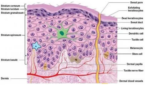
The (figure 1-1) shows the structure of skin. The skin is protecting our body against the external environment damages. The vital and important functions that are executing by the skin have been classified in (figure 1-2)
Page 3
Figure 1-2) the key factors of skin 1.1.1 The population of cells in skin
As (figure 1-3) shown, we can see there are several types of cells in different layers of skin where each type has own responsibilities. As before said each of cells group have certain function that are classified as below: Keratinocytes those are located in the epidermis, have highly immunogenic. Fibroblasts in the dermis layer, have moderately immunogenic compared with keratinocytes. Dendritic cells (DCs) can be considered as antigen-presenting cells of the immune system. Their main application is to execute antigen material and illustrate it on the cell surface to the T cells of the immune system. They have been mentioning as messengers between the innate and the adaptive immune system.
The skin can be
considered as a
Barrier to
chemical and biological pathogens
physical mechanical radiation
Metabolic converts precursor molecules to vitamin D within the metabolism of Calcium
Sensory-touch including position, pain and pleasure sensitivity
Homeostatic it prevents dehidration and regulates body temperature
Secretory -
Page 4
Figure1-3) the cells population (Raimondi) 1.1.2 Repair
Here we have introduced the procedure of skin’s repair. The process will be started right after the skin is injured. This procedure has been called epidermal cross-talk. The process is summarized in four steps as below:
Figure 1-4) the procedure of epidermal cross-walk (Raimondi)
1. The platelets adhere to the collagen of the ECM; the fibrinogen secreted by the liver cells binds to the thrombin present on the platelets to form fibrin which aggregates the blood clot; the clot serves as a scaffold for infiltration of other cells in the area (macrophages, neutrophils, T lymphocytes and platelets).
2. Peri-lesional keratinocytes release inteleukine-1 (IK-1) and tumor necrosis factor α (TNF-α) that recall cells of the immune system and fibroblasts that form the granulation tissue
Page 5 3. Macrophages, neutrophils, T lymphocytes and platelets produce endothelial growth factor (EGF), transforming growth factor β (TGF-β), platelet-derived growth factor (PDGF) and various inflammatory cytokines that induce remodelling of the granulation tissue 4. The fibroblasts that progressively migrate and repopulate the area secrete keratinocyte
Growth Factor (KGF) that in turn stimulate keratinocyte proliferation and re-epithelialisation.
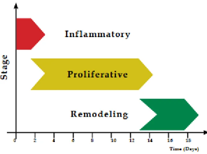
In the following we have shown that skin would healing has three main steps (figure 1-5).
Inflammatory (From Inflammation to Proliferation): it is first stage right after tissue lesion.
In this stage the lesioned blood vessels will be contracted. As the result, the leaked blood coagulates is happened, contributing to the maintenance of its integrity.
Inflammatory cells can be considered as an important in wound healing that play main role contribute to the release of lysosomal enzymes and reactive oxygen species, as well as speed up the clean-up of various cell debris. The T-cells can be considered as important inflammatory cells.” Activated regulatory T cells are part of the adaptive immune system. Aside from leukocytes, regulatory T cells are able to regulate tissue inflammation via the attenuation of the interferon-γ production and the accumulation of pro-inflammatory macrophages” (Heiko Sorga Daniel, 2016).
Proliferative: it is the second stage. The main function the proliferative stage is to remove
the lesioned tissue area through contraction and fibroplasia, establishing a viable epithelial barrier to activate keratinocytes. The responsibility of this stage is, to make smaller and even the closure of the lesion area that executes angiogenesis, fibroplasia, and re-epithelialisation.
Page 6
Remodelling: it is the third and last stage of healing that will be started two to three weeks
after the birth of the lesion and it is possible to continue for one year or more. The main gaol of this stage is to reach the maximum tensile strength through reorganization, degradation, and resynthesize of the extracellular matrix. In this last stage, an attempt to recover the normal tissue structure occurs, and the granulation tissue is gradually remodelled, shaping scar tissue that is less cellular and vascular and that represents a promoted increase in its concentration of collagen fibres.
1.1.3 The relation between oxygen’s role and skin wound healing
In recent years some researchers around monitoring of oxygen concentration in mammalian cells have been done. One of them is done by Bremen University where a collaboration between is institution of micro-sensor and actuator system (IMSAS) and faculty of biology and chemistry (Frank Bungea, 2019) (Heiko Sorga Daniel, 2016).
In this article the HaCaT-cells have been used. The cell experiments are done with HaCaT-cells which are human keratinocyte cell line. They are widely being using in research area. As before said the T-cells are playing key role in first step of skin wound healing. They have been considered as a part of the adaptive immune system where they can regulate tissue inflammation. As before said the HaCaT-cells are so practical in research area, especially for modeling of characterization of human keratinocyte.
“Currently the most exciting insight from zebrafish studies of wound inflammation has been that reactive oxygen species like hydrogen peroxide can serve as immediate damage attractants to draw immune cells to wounds” (Nunan, 2015).
1.2 Microfluidic devices
In recent past decades among most of scientific researchers and industrial issues, the microfluidic devices has being considering as one most popular tools and integrated system that have a lot advantages. Scientists have gotten result that microfluidics devices provide new way in medical area. Recently microfluidics are being mostly using in many fields of biology and chemistry, such as lab on a chip(LOC) and micro total analysis systems(mTAS).
Nowadays by the development of technology, scientists and experts in every field have been searching to figure out novel methods to speed up healing procedures in the medical area. These methods should be effective in two topics, cost and time. The microfluidic devices can be mentioned as one of the most practical devices that are efficient in time and cost that they increase efficiency in both cases. In the following, we explained them sufficiently.
Microfluidics can be defined as practical tools to handling, monitoring and analysis of different samples and liquids at the scales in micrometer level. Also microfluidics devices give us benefits to
Page 7 combine several functions of laboratory onto a single chip. So this credit is over traditional one (assays) that is used in cell biology. These mentioned devices currently are called as miniaturized total analysis systems (µTASs) or lab-on-chip (LoC) technologies that have capability of (a) providing scalability and batch screening of multiple samples, (b) accurately manipulating the cell microenvironment to acquire maximum information, and (c) streamlining complicated assay protocols, (d) reducing substantial cost and sample volume (Chee Meng Benjamin Hoa).
In recent academic and scientific works, the microfluidic device is one of the most popular tools in medical diagnoses. By using microfluidic devices several fields have been gotten benefits such as reaction ware, genetic analysis, cell analysis, drug discovery, point-of-care (POC) diagnostics, and organs on chips (Yong He Y. W.-z.-j., 2016).
As before said the advantage of this device is reducing wildly time and cost. By using a little amount of samples, the speed of the analysis procedure has been increased. In this way the consumption rate of samples and reagents is decreased substantially and you can save your time and cost. Also the other credits of microfluidic devices are the scalability and small volume that have been wildly noticed in measurements. Especially it is considered in the measurement of intracellular and secreted proteins from single cells. For this reason single molecule imaging is placed in a parallel microfluidic structure to measure intracellular protein expression, the library is over 1018 fluorescent protein fusion strains(figure 1-6) (Ve´ ronique Lecault, 2012).
Figure 1-6) schematic of Microfluidic structure for analysis of single cell intracellular model (Ve´ ronique Lecault, 2012)
Microfluidic can be taken to account as a powerful tool in separation samples as process of electrophoresis. Electrophoresis process and microfluidics structure represent great compatibility with each other. With short channel networks and the ability to apply high field strengths, electrophoresis can be performed within a short time, which is of great value for near real-time detection on small volume samples (Chengpeng Chen, 2016) (S. Attiya, 2001).
Page 8 One most popular microfluidic devices are digital microfluidic devices (DMF).The principle is like as microfluidic channels. Nowadays most digital microfluidic devices work based on this structure. It can be used analytically to study the properties of a single charged species or combination of several molecules. It uses as a preoperative method in separating technique. (Shih, 2010).
In Digital microfluidics (DMF) technique the droplets are being manipulating in microfluidic channel by applying electrical fields to an array of electrodes. Also there is an advantage with this technique in which all procedures and reactions can be executed without cross-talk among samples. Because droplets remind as a discrete micro-vessels (figure 1-7) (Shih, 2010). In contrast to the more conventional geometry of enclosed and integrated microchannels like as chamber, each sample on a DMF device can be addressed individually, and reagents can be dispensed from reservoirs, moved, merged, and split.
There are a lot of interesting applications of DMF technique such as: analysis of DNA sample, cell culture, protein sample analysis, enzyme assays, immunoassays, and clinical sample processing. Despite this abovementioned interesting applications, the technology is not still adopted, and there are big challenges that influence its widespread adoption in the lab-on-a-chip community (Shih, 2010).
Figure 1-7) Schematics of the droplet control system (measurement circuit and circuit of DMF device) (Shih, 2010)
One of the most practical useable microfluidic structure in medical and industrial areas, it is the monitoring of oxygen concentration in liquid and cells especially. On the other hand, the
Page 9 cultivation of cells on-chip can be considered as another useable aspect of microfluidic devices. In the following, we are going to represent the structure of microfluidic sensors on different topics.
1.3 Review of some microfluidic sensor’s structures
In this section we present microfluidic sensors for biology and biomedical application from several articles that are published in last years. All of following structures are made through deposition method.
1.3.1 Microfluidic Oxygen Imaging using Integrated Optical Sensor Layers and a Color Camera
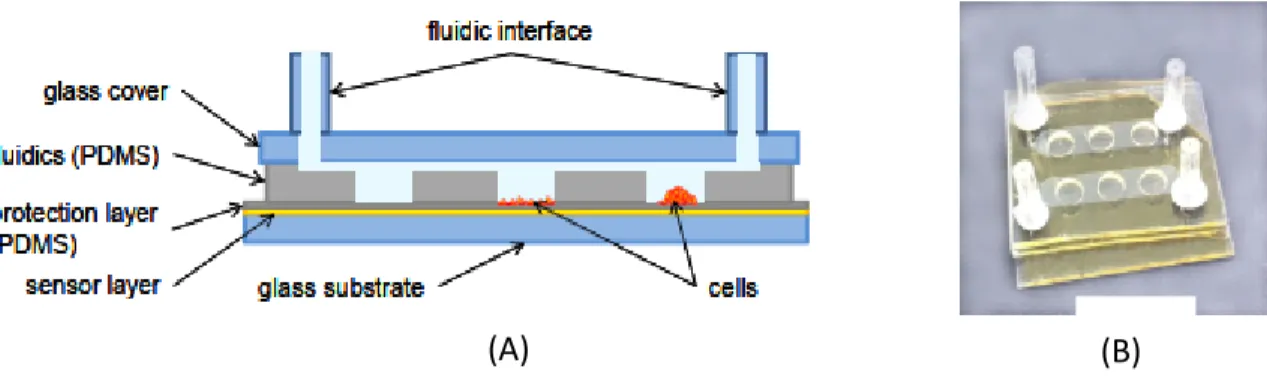
This work is used to shows a high-resolution oxygen imaging. The study has been used to analysis 2D oxygen distribution in microfluidic structure. For this reason a color CCD-camera has been used to compare the intensity of imaging in different wave length. (Figure 1-8) shows present a schematic cross-section and an image of entire structure of the microfluidic chip with an integrated oxygen sensor layer.
Figure 1-8) Microfluidic oxygen sensor chip; A) photo of structure in cross section of the chip B) Photo of the actual cell-chip device with two divided microfluidic channels and three O2-sensitive cell cultivation chambers
where are positioned on each channel (Birgit Ungerböck).
The microfluidic oxygen sensor a chip is included a glass layer; the channels part where made of PDMS, a sensor layer with a protection film and a glass cover as represented in (figure 1-3). Here the advantage of chip is used protection to promote mechanical stability. Because after while in liquid environments the adhesion between dry sensor layer and glass will be decreased. For this reason the PDMS spin coated on sensor layer. PDMS has high gas permeability that is enough for majority of biological applications.
Page 10 Furthermore by this structure we are ensured to measure oxygen concentration and the cells are place in the minimal distance, the cells are really surrounded by instead of less relevant information on oxygen in the bulk medium (Birgit Ungerböck).
1.3.2 Microfluidic oxygen sensor system as a tool to monitor the metabolism of mammalian cells
(Figure 1-9) shows a sensor system for monitoring the consumption rate of oxygen by mammalian, by this the oxygen consumption rate is used as a direct indicator tool that has a direct relation to cell metabolism. All of these requirements have been provided for Biolab usage. These considerations are included a simple setup to sense oxygen where it should be fabricated as small and reliable as possible, biocompatible materials in which they have the proper features for a high degree of automation and integration.
These above-mentioned requirements are satisfied by a setup that consists of heater and temperature sensor conductors that are placed backside the chip, a chip with microfluidic channel where on top it an integrated oxygen-sensitive phosphorescent film is glued to glass, for read-out control temperature there are external optical read-out and electronic feedback circuit respectively, and 3D-printed holders and housing.
Figure 1-9) the structure of the microfluidic chip to monitor the oxygen consumption rate of cultivated cells through measuring the concentration of dissolved oxygen (Frank Bungea, 2019).
The sensor a system is based on three main sections; consist of an external excitation LEDs, a microfluidic chip with phosphorescent spots where the chip contains a closed microfluidic channel
Page 11 out of silicon and glass and a camera for the read-out. All sections are mounted together with 3D-printed parts (Figure 1-9).
This channel can be filled and emptied with the sample liquid and the mammalian cells through its inlet and outlet where are located in the backside of the chip. Besides, an oxygen-sensitive film is deposited on the backside of the glass that near to the microfluidic channel. The sensing of the dissolved oxygen is based on the photoluminescence phenomenon. The phosphorescence spot is excited by LED then the sensing spot starts to emit light. By the observation the intensity of emitted light decreases as much as the oxygen concentration is increasing. Finally, the intensity of phosphorescent light is measured with a detector (Frank Bungea, 2019).
1.3.3 Microfluidic oxygen sensor based on silica gels for long-term experiment
Long-term measurements have been always considering as one of the important factors in experimental works. Especially in microfluidic systems where filled by samples like dissolved oxygen. For this consideration, there are two main reasons, (i) the photo-oxidation of the sensing film that consumes oxygen, (ii) the increasing of uncertain fluctuation of the temperature. In this work (figure 1-10), a microfluidic chip is presented in which fabricated by glass and silicon. The integrated phosphorescent spots are patterned on the backside of glass near to chamber. The great difference between these sensors compared to a conventional one is the reduction of oxygen consumption (around 36 times).
Because in this study the sensing spots are made of elements that are composed of a matrix of silica gel and an oxygen-sensitive dye (PtTFPP) that can be taken into account as an organic matrix structure. Also, for removing out the effect of the temperature, an integrated temperature sensor, and heating elements is designed on the chip. (Frank Bunge, MICROFLUIDIC OXYGEN SENSOR BASED ON SILICA GELS FOR LONHTERM EXPERIMENTS, 2018).
Page 12
Figure 1-10) schematic structure of the microfluidic chip for measuring the concentration of dissolved oxygen in the measurement channel (height: 200μm) with an integrated temperature sensor and heater that made out of
platinum (Frank Bunge, MICROFLUIDIC OXYGEN SENSOR BASED ON SILICA GELS FOR LONHTERM EXPERIMENTS, 2018).
As shown in (Figure 1-11) the chip is made out of silicon and of a glass layer. The silicon is included one 200 μm deep microfluidic channel with a width of 2.5 mm and a length of 12.3 mm. besides, the channel is connected via inlets with a diameter of 0.7 mm to the outer world.
Figure 1-11) photo of the microfluidic channel chip Left: bottom view with inlets and the electrical heating and temperature sensing element based on the change of the resistivity. Right: top view with the microfluidic
channels and the phosphorescent spots.
According to (figure 1-11) there are two traces conductors that are made out of platinum which are isolated against the silicon via 100 nm thick silicon oxide, have a resistance of 1.7 kΩ and 100 Ω sequentially. These have been designed as a heater and a temperature sensor.
The glass layer closes the chamber hermetically. In sum, five circular sensing elements with a diameter of 1.3 mm are patterned on the glass. (Frank Bunge, MICROFLUIDIC OXYGEN SENSOR BASED ON SILICA GELS FOR LONHTERM EXPERIMENTS, 2018).
Page 13
1.3.4 PDMS-free microfluidic cell culture with integrated gas supply through a porous membrane of anodized aluminum oxide
In this structure a microfluidic device has two separated chamber, one or cell cultivation and the other one for the gas supply. Both chambers have been separated through a membrane that is gas permeable due to avoid liquids leakage.
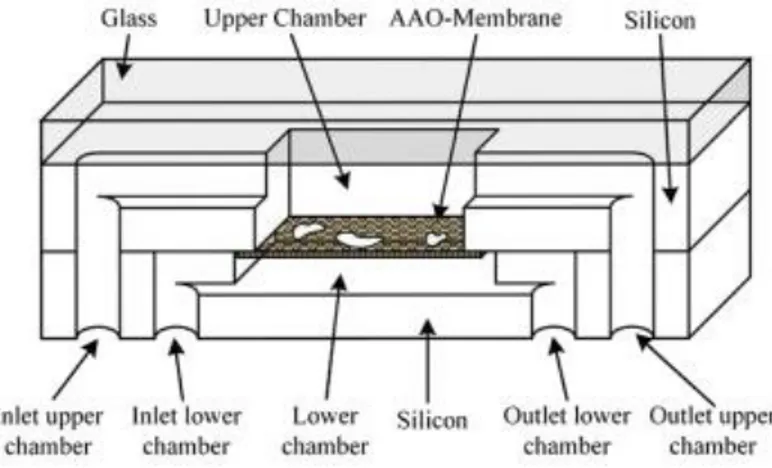
As shown in (figure 1-12) the microfluidic chip structure is included a vertical membrane that is made out of AAO where a lower from an upper chamber have been separated by AAO membrane. The two chambers have been etched in one silicon layer. Both the upper silicon layer and lower one have their own chamber where each one also has separated inlet and outlet. The membrane has uniformly been fixed on the bottom side of the upper layer. By this design it is placed close the device, an unstructured borosilicate wafer is restricted on top. As the result, optical control of both chambers would be better as AAO is also transparent. The cells have been cultured in the upper chamber on top of the membrane. Consequently, the lower chamber will be filled with air that diffuses through the membrane towards the culture chamber.
Figure 1-12) structure of the microfluidic chip to cultivate mammalian cells (Vellekoop, 2018)
In mentioned study, the membrane has been made out of anodized aluminum oxide (AAO) (Bunge C. H., 2018). In the anodization procedure, the aluminum will be transformed to AAO. As the results, unidirectional pores from the top to the bottom of the membrane will be generated. The inner pore distances can be varied approximately between 20 and 500 nm. It is completely depend on the applied voltage during the anodization and the electrolyte (Vellekoop, 2018).
Page 14
Figure 1-13) gap between air and liquid that has been pressed out of a pore of AAO (Vellekoop, 2018)
After the anodization process, it is possible the pores will be broadening through wet-etching technique with phosphoric acid. In addition, AAO is hydrophilic. As a consequently the pores are being filling as immediate as once they will in contact with water. By applying more pressure, the liquid will be pressed out of the pore and form a small arc shape on the outer side (figure 1-13).
1.3.5 Spatially monitoring oxygen level in 3D micro-fabricated cell culture systems using optical oxygen sensing beads
In this structure there are oxygen sensing beads to monitoring and tracking of oxygen concentration in 3D micro-patterned cell culture system. For this reason the used cells are Human intestinal epithelial Caco-2 cells. The principle of sensing bead is based on the reversible luminescence quenching of Ru(Ph2phen3)Cl2 by oxygen. The size of beads are tens of microns and contain a core of silica filled with both the sensitive Ru(Ph2phen3)Cl2 dye and an oxygen-insensitive Nile Blue dye. The beads are covered by biocompatible shell and oxygen permeable polydimethylsiloxane (PDMS) (figure 1-14).
The oxygen sensing beads were cultivated on two different structures, series of PDMS and type I collagen with micro-well arrays for three or seven days, and then brought into contact with oxygen sensing beads. Chemical composition of cell culture substrates also appeared to affect oxygen level, with type-I collagen based cell culture systems having lower oxygen concentration compared to PDMS based cell culture systems.
Page 15
Figure 1-14) Schematic drawing of the composition and structure of oxygen sensing beads and application of oxygen sensing beads to PDMS and collagen based 3D intestinal epithelial Caco-2 culture system for real time
mapping of oxygen level distribution on the culture surface (Lin Wang M. A., 2013).
Results generally demonstrated lower oxygen level inside wells compared to on top of wells, also local oxygen level is dependent on structural features of cell culture surfaces. In general speaking, results suggest that oxygen sensing beads can be utilized to achieve real-time and local monitoring of micro-environment oxygen level in 3D micro fabricated cell culture systems (Lin Wang M. A., 2013).
1.4 Review of chip fabrication and film fabrication
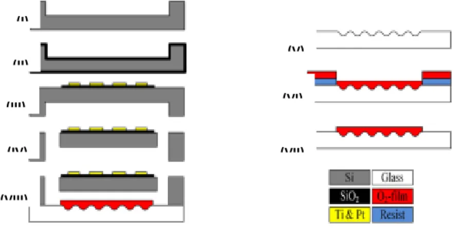
In the recent decades around Fifty-two devices are made once out of a glass and a silicon wafer. The silicon layer contains the 200 µm deep microfluidic channels which are fabricated by a dry-etching technique. Furthermore, from the backside of the wafer, the inlet and outlet are etched as well with a DRIE-process. As shown in (Figure 1-15), the fabrication process has eight main steps. (I), the chamber and the channels are etched into the 380 μm thick silicon wafer through a DRIE-process with 200 μm deep. (II), to isolate the wafer a 100 nm thick silicon oxide layer that is used as an isolation layer is oxidized on the silicon layer. (III), the oxide is patterned with wet-etching and 5 nm titanium and 100 nm platinum have been deposited. (IV), to develop the adhesion for platinum, titanium can be mentioned as a proper substrate for the platinum out of that the electrical heater and temperature sensor are shaped through a lift-off process. The inlet and outlet are etched into the silicon by dry-etching technique (Frank Bungea, 2019).
Page 16
Figure 1-15) schematic of Fabrication of the microfluidic chip (Frank Bunge, µRESPIROMETER TO DETERMINE THE OXYGEN CONSUMPTION RATE OF MAMMALIAN CELLS IN MICROFLUIDIC CULTURE, 2017)
(V), in this step to increase the adhesion between position of oxygen sensitive film and the glass wafer, the glass wafer has been roughened by powder blasting. (VI), the dry film resist Etertec E8015 is deposited and positioned on the wafer. Subsequently, a cocktail of 10 ml toluol, 500 mg PS, and 10 mg PtTFPP has been combined and placed in a vacuum to form the PSPtTFPP-film by evaporation of the toluol. (VII) After 1-hour vacuum treatment, the extra parts of film is removed out by a lift-off-process of the dry-film-resist during two hours in a CaCO3-solution. (VIII) Finally, the glass-wafer and silicon wafer are bonded anodically to each other. The entire process is summarized in (figure 1-15) (Frank Bunge, µRESPIROMETER TO DETERMINE THE OXYGEN CONSUMPTION RATE OF MAMMALIAN CELLS IN MICROFLUIDIC CULTURE, 2017).
1.4.1 Film Fabrication
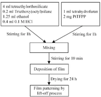
The sensing dye is quenched by oxygen but also by water. Consequently, the matrix has to be porous but hydrophobic so that the pores are not filled with the sample liquid, but with gases that interact with the dye. To obtain a hydrophobic matrix, a small amount of triethoxy (octyl) silane is added. The entire fabrication recipe is summarized in (figure 1-16).
(V) (IV) (III) (II) (I) (VIII) (VII) (VI)
Page 17
Figure 1-16) Fabrication of the oxygen sensitive film based on tetraethyl orthosilicate (TEOS) (Frank Bunge, MICROFLUIDIC OXYGEN SENSOR BASED ON SILICA GELS FOR LONHTERM EXPERIMENTS, 2018)
The film containing the Ormosil-matrix is compared with a conventional film with a polystyrene-matrix as described earlier. Here, 10 mg PtTFPP and 500 mg polystyrene are dissolved in 10 mL toluol. After 10 mins of mixing, the film is deposited on the wafer and the solvent is removed by evaporate.
Page 18
2 The 3D printed Microfluidic devices
In past decade a lot of researchers have been done around the 3D printed microfluidic devices (Chee Meng Benjamin Hoa) (Chengpeng Chen, 2016) (Comina G, 2013) (al G. B., 2015). As before said the microfluidic devices are being as one of the powerful tools in medical, chemistry, biomedical and biological areas such as; micro-physiological system engineering, cancer monitoring, high-throughput drug testing, and point-of care diagnostics (Reza Amin, 2016). Some of the key functions of a microfluidic device are sample preparation, separations of liquids, detection and fluid manipulation.
However conventional technique of microfluidic devices fabrication is complicated takes a lot of time and requires expensive properties, equipment and advance cleanroom facilities. The 3D printed technique can be more reliable than conventional procedures like as PDMS- glass bonding and lithography, because the 3D printing technique not only provide irritation of complicated designs, easy accessibility and quick fabrication but also reduced cost in all areas such as; maintenance, installation and physical space.
Once our design has already been finished, the immediate way to prototype the microfluidic device is the PDMS casting based 3D molding (soft lithography). To make the microfluidic device, firstly, our design should be designed by computer-aided design (Autodesk Invertor, CAD) or other engineering drawing software. Afterwards the channels would be molded on a SU-8 master or a piece of metal using laser cutting technique. By using the Autodesk invertor a benefit will be given to user to design channel and other integrated parts that know their dimensions as well at the same time. After the fabrication of the mold, polydimethylsiloxane (PDMS) polymer will be filled into the master mold and cure for over 2 hours. The PDMS will have been peeled from the master then cut into the shape of the desired device just after the curing procedure. Besides 3D printing is not depending on masks pattern to create the micro pattern one, instead, it takes part from the input CAD software. Hence, it is able to produce defined structures in a full completed 3D space arbitrary, without great increase in fabrication complexity and time (Chee Meng Benjamin Hoa). Once the masks have been fabricated, it will take a few hours to possibly one or two days of production, depending on the number of chips required. However, the process of getting the final microfluidics design is a tedious one. Initial microfluidic testing may reveal design flaws and performance deficiencies require the user to modify the design, therefore incurring significant delay and stretch the development time with an increase in cost. Besides making molds, the ability of 3D printing offers the opportunity to fabricate the whole microfluidics device in a single step with no need for and assembly as with PDMS. Recently, a 3D printed microfluidic device with integrated membrane-based valves was fabricated (C. I. Rogers, 2015).
3D printing can be imaged just like an inverse process of potato cutting in some slices in the kitchen. A potato is cut into many pieces by a certain thickness size and a certain direction as what
Page 19 we want or are desired for design. Inversely, it is possible that all potato chips can be glued together again to form an entire potato, in which just likes the layer-by-layer fabrication of the 3D printing procedure. Firstly, it should be acquired 3D digital models from the computer (Autodesk Invertor) software or the 3D scanners. After that, slicer software is used to provide a series of layers by Z-direction discrete from the 3D models. Finally, a 3D unity is fabricated through layer by layer printing, placed over each other through layer by layer superposition. The specific 3D printing process is shown in (figure 2-1). (Yong He Y. W.-z.-j., 2016).
Figure 2-1) 3D printing process (Yong He Y. W.-z.-j., 2016)
2.1 Materials for 3D-printed microfluidics
The 3D printing material properties can be considered as one of important factor in the fabrication processes. Because the manufacturing process, post-processing and the usage of 3D printed microfluidic devices are completely depended on material properties. The other reasons regard to material considerations are mainly due to the leading trend of 3D printing technologies and the convenient new materials that are yet to be investigated for standardization in which we have not honestly reached to this desired standardization yet.
Some important relevant factors of these properties are such as; transparency, printability, biocompatibility, viscosity, and elastic modulus which Elastic modulus is the mechanical feature represents relationship between stress and strain that is great practical in designing pieces such as valves and channels that have to tolerate high fluid pressure. In elastic modulus case, the microfluidics not only faces with such small quantities of fluid, but also it deals with an elastic
Page 20 deformation in the valve and channel. So the pressure pumping through these devices should be enough to deals mentioned obstacles. All mentioned properties provide scientific area for researcher to figure out proper material to reach desired device applications.
In the microfluidic fabrication process, transparency of materials is also should be noted as a useful property. In microfluidics, in order to take a test and experiment, it is necessary to have great visual observations to ensure the samples are interacting properly and flowing suitability. In addition, in biological applications of microfluidics, cells can be imaged based on optical phenomena such as using either transmitted light or epifluorescence. Nowadays PDMS is currently used for fabricating microfluidic devices because of its excellent transparency. Although PDMS is widely well known for its perfect optical transparency. However, it should be noted that because of the light-polymerization method used in Stereolithography (SLA)3D printing, especially, in the case of transparent resins, there may be a situation with unintentionally curing layers above the layer where is being printed. UV blockers are often added to the resins to face with this problem, but these blockers can be appeared as a noise with high level of light reflection that causes to restrict the observation of image fluorescent molecules in low wavelengths.
In general speaking, SLA resins are designed to polymerize under a certain wavelength (often in the UV range), making cross-compatibility between resins and 3D printers limited. Moreover, resin viscosity is an important parameter to select a proper method for the removal of uncured resin from 3D-printed channels. The printing resolution is also dependent on materials.
Due to differences in material properties, a single device may have slightly different dimensions when printed on different types of 3D printers. On the other hand, in the case of Fused Deposition Modeling (FDM) materials, it is important to mention the level of bonding strength between the layers. As most of the Microfluidic applications are often being involving with biomaterials or chemical reagents. So the chemical composition of the resin is critical to make the 3D-printed devices a reliable option.
As before said, device applications can be considered as practical tools in the biomedical area, so they should be made of resins that will not have any reaction like absorption with protein and nucleic acid reagents. Similarly, resins should be biocompatible, as living cells may come into contact or be cultured in close proximity with the resin. The transparency and biocompatibility of both SLA and multi-jet resins have been considered as a sufficient factor for biological experiments. In light of highly interesting properties of existing resins as well as active innovation in this area, use of 3D printing materials to create microfluidic devices has gained popularity. (Reza Amin, 2016).
Page 21
2.1.1 Fabrication of molds for PDMS-based microfluidics
PDMS is one of the most useable materials in 3D printed fabrication. Manufacturing PDMS-based microfluidics by using 3Dprinted master molds provides many of the benefits of 3D printing fabrication and keeps the favourable PDMS material properties such as oxygen permeability and biocompatibility properly. This approach also faces the disadvantage of unknown surface properties of commercial resins (al G. B., 2015).
The master is produced through immediate prototyping methods, reduction of total required time and cost for fabrication, followed by traditional PDMS molding. We can understand that the fabricated devices based on PDMS are convenient due to the missing of the cleanroom step in the fabrication process. Using this approach, microfluidic devices with structures of 10 μm have been generated at a low average cost (reported by one study to be approximately 0.48$US per chip) (Comina G, 2013) (Reza Amin, 2016).
The PDMS films are able to incorporate with integrated substrates that may be produced separately from this process. This method has several advantages including the printed chip’s compatibility to various detection methods for example; the lab-on-a-chip device functionality was illustrated through its ability to detectH2O2 concentration in blood. In addition, to the low cost per device (Reza Amin, 2016).
Use of 3D-printed molds for PDMS devices is particularly promising for cell culture applications. The use of a 3D-printed-soft lithography mold to test concentration gradients is usable for biomedical applications (al K. K., 2015). Besides the design and fabrication of 3D-printed microfluidic electrical cell lysis devices that are coated with PDMS or polystyrene to promote the cellular adherence for cell lysis (al G. B., 2015).
In addition, the thin PDMS coating served as the glue for the fluidic layer. This is an available way of assembly for PDMS oxygen-sensitive probes are located in the medium surrounding the cells. In the presented device distance of the sensing layer to the cells is well defined and reproducible.
2.2 3D printing technologies
In this section we are going to introduce three common 3D printing techniques out of a lot of methods. The topics are included the principles of methods, comparison between techniques in all aspects. Also the used materials have been discussed.
2.2.1 Stereolithography
Stereolithography is known as one of the first commercialized 3D printing technique, in which a prototype or a model is manufactured through curing the 2D layers of the polymer. SLA was first introduced by Chuck Hull. In the first step of the procedure, an STL file will be sliced to acquire the
Page 22 information of each of the 2D layers that have to print by a focused ultraviolet (UV) laser light. This UV light supplies there is an external power source in which is being supplied by the UV light to initiate the chain reaction of photopolymerization. By scanning each layer, the entire fabricated platform is needed to be lowered to the resin can fill a layer thickness above the deposited structure, then further laser-scanned will be repeated. These mentioned steps are repeated again and again until the whole structure will be shaped. The photopolymers are transformed into chains of polymer to have got attached to the next layer through radicalization. Also, there is an unreacted resin that helps to hold the structure is removed after completion of the process. The resolution of the process is as precise as 10 μm and hence, a high-quality accurate sensor can print by this SLA technique. One of the main notable advantages of this technique lies in the possible fabrication of large volume structures by this process (Tao Han, April 2019).
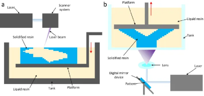
Figure 2-2) the fundamental of (a) SLA and (b) DLP (Tao Han, April 2019)
SLA is a 3D printing technique that is based on optical modeling that uses liquid photosensitive resin as a material. (Figure 2-2(a)) represents the fundamentals of SLA. The tank is filled with a liquid photosensitive resin that changes from liquid to solid because light-polymerization happened immediately with the explosion of ultraviolet light with determined wavelength and strength. The laser tracks the layered cross-section by the control of the computer and exposure to the liquid resin in the tank, leaving the layer cured. Then, the lift decreases the height of a layer, and the formed layer is covered with a layer of liquid resin. Then a new layer will be scanned, after that the newly cured layer toughly glues on the front layer. Repeat the above-mentioned steps until the whole part is fabricated and a three-dimensional solid model are acquired.
Page 23 But in the DLP technique, the process is different compared to SLA. It uses a UV lamp or a laser with a mask as a light source. At the first, the photosensitive resin has been exposed to the light by special patterns or models on a digital mirror device. Secondly, the exposed sections will be cured and one layer is completed. Then, the platform raises a gap of a layer and further exposure begins. According to (figures 2-2(a) and (b)) the main difference between SLA and DLP techniques is the usage of a mask. SLA is mask less which uses a moving laser directly while DLP has been executed through a digital mirror device as a dynamic mask. Due to the resolution of the digital mirror, the DLP 3D printers are being usually used in printing structures less than 200 mm, which is the proper method for printing microfluidics. Also, the good news is the price of DLP 3D printer is being reduced rapidly; the majority of them can be bought for less than $ 7000 (Yong He Y. W.-z.-j., 2016).
2.2.2 Photomelting
Photomelting is another 3D printing technique, which uses powdery materials mainly are included ceramic, metal, wax, plastic, etc. so the feature illustrates that photomelting is a physical process. SLM (Selective Laser Melting) or SLS (Selective Laser Sintering) (figure 2-3), is using the material in powdery shapes, such as plastic, metal, ceramic. A layer of powder has been tiled on the workbench.
A high-strength laser is monitoring by computer is being used to scan the profile and the scanned part has been sintered that to be a section. After that, a new layer of powder is tiled on the upper surface of the molded part again. The laser scans again so that the powder can be sintered and bonds with the under part which is molded. Repeat the entire steps until the solid model is fabricated. Finally, remove the excess powder and a sintered part appears (Yong He Y. W.-z.-j., 2016).
Page 24
Figure 2-3) the fundamental of SLS/SLM (Yong He Y. W.-z.-j., 2016)
2.2.3 Inkjet-based 3D Printing
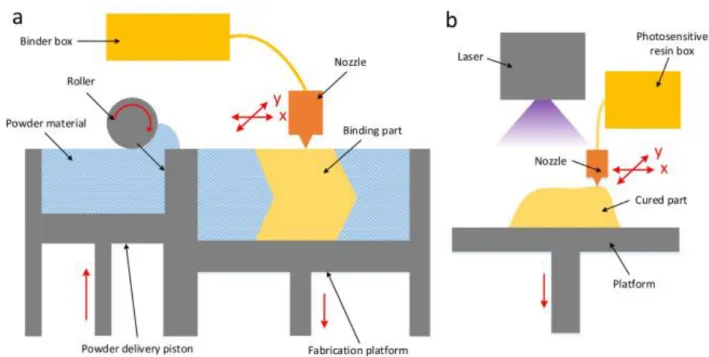
The inkjet-based 3D printing technique has two different types of methods, the 3DP-Powder (3DP-P) and the 3DPLiquidResin (3DP-LR). The 3DP-P is more common compared to 3DP-LR. The printer is using special adhesives to bond the layers of powder material, and a new layer has been deposited on the past one (Figure 2-4(a)).
It can be considered different powder materials that are using in the 3DP-P technique, such as sugar, plaster, and ceramics. One of the biggest benefits of 3DP-P is that it is being used to fabricate promise color products that require rich color and strong ability of expression, like architectural models. The products printed by 3DP-P do not require extra supporting material, because the powders can support as much as themselves, and the remaining materials are able to reuse. As the powder is more glued together, the leaking liquid is a great barrier that has been limited its use in directly printed microfluidics.
Page 25
Figure 2-4) the fundamental of inkjet-based 3DP. (a) 3DP-P; (b) 3DP-LR (Yong He Y. W.-z.-j., 2016)
But in the second type, 3DP-LR, the photosensitive resin is usually using as the printing material. The photosensitive resin is throwing out from an inkjet nozzle them has been cured through the light to form a layer of product. A 3D product can be received after the curing layer by layer (figure 2-4(b)). This mentioned technique can manufacture products with high factor in accuracy and is widely applied to the fabrication of microfluidics. Although the cost of 3DP-LR is expensive (Yong He Y. W.-z.-j., 2016).
2.3 The advantages and disadvantages of 3D printed Microfluidic devices 2.3.1 Benefits of 3D printed Microfluidic devices
The usage of 3D printing for the manufacturing of microfluidics devices is providing big advantage for biological and medical applications. The 3D printing can be called as a “skill-less” fabrication method that has the ability to replace soft lithography as the well-known technique for the fabrication of microfluidic devices that do not need extensive, high-density automation. Also the opportunely has been given to biomedical scientists to have direct access to the “immediate manufacturing” of microfluidic devices (A. K. Au, 2014).
This technology has the ability to change approach of researchers in both collaboration and experimental designs aspects. Because we have restricted knowledge in this area, particularly in biological studies, in which spatial control and monitoring of samples or cells is vital into 3D printed microfluidic devices.
Page 26 By using 3D printing, some search about the destructive application for microfluidics can be figured out as soon as possible. It is meant; 3D printed microfluidic devices can be mentioned as powerful tools that dramatically decrease the barrier for the fabrication of advance microfluidic devices. Also, it offers a promise rapid-foot printing ability with its attendant advantages to positively interrupt microfluidic development cycles. Besides, the 3D-printed tendency can be illustrated as an intermediate level between 3D printed microfluidic devices and PDMS-glass microfluidic devices, which has the potential to take advantage of the rapid prototyping capabilities of 3D printing as well as the benefits of traditional and conventional PDMS-glass microfluidic devices. Also in last decades, 3D-printable material have been presenting as great consideration unique to the 3D printing orientation as well as a direction for future innovation (Reza Amin, 2016).
Another benefit of 3D printed devices that makes them so practical is that they can be printed on demand. So we can print models as much as we required. The 3D printed devices are easy-use and convenient. It is meant; the design files can easily be shared through online or as part of the publication process. For this reason technology is sharing between laboratories in a reproducible way (Kari B. Anderson).
3D-printing can be considered as an effective technique to manufacture structurally robust integrated microfluidic devices. In addition, 3D-printing are able to create the unique fabrication but in beneficial features integrated ways on a microfluidic device. Although integrated components have been created with PDMS devices, but this process has a lot of time consuming and costly to integrate multiple functional units on one device (J. M. K. Ng, 2002).Because 3D-printing can produce any shape based on users' demand, complex and functional 3D-printed microfluidic features have been reported (Chengpeng Chen, 2016).
The microfluidic structures have also influenced the cell culture application in a positive manner. The great benefit of microfluidic cell cultures compared to a traditional one is in well-plates where is providing a higher degree of freedom that allows building co-cultures with other cell types at the same time that can be mentioned as 3D-cell cultures integrated sensors or to culture cells with different adapted supply scenarios. However, the supply of the cells with gases, nutrients or sample reactants such as drugs or toxic components is an essential feature of all systems (Vellekoop, 2018).
2.3.2 Limitation of 3D Printed Microfluidics
Although nowadays 3D printed microfluidics is being developing immediately, some challenges deflects are still remained. The restrictions of 3D printed microfluidics have been classified into two groups, material and accuracy. There is a clear deflection and gap between 3D printing and
Page 27 the traditional MEMS technology in accuracy, which means majority of 3D printing techniques, are not proper for the fabrication of Nano fluidics.
While D3DPs directly are being using to print microfluidics, leakage maybe a big problem. Furthermore, although 3D printer is an efficient and an available tool for microfluidic fabrication, it doesn’t mean that 3D printer can print everything. In the opposite, the materials which are being aiming for 3D printing are rather limited. Some materials such as glass and silicon cannot be directly printed for microfluidics because they are hydrophilic. Also, some polymers that are appropriate for printing such as PLA and ABS need the pre-process to develop the hydrophilic properties when used in the fabrication of microfluidics.
By developing of 3D printing rapidly, more powerful and suitable materials are expected for microfluidics. Due to the restrictions of accuracy and material, 3D printing has generally been combined to other processes, such as casting, plating and deposition, by which the power and efficiency of 3D printing can be reached to maximum level as soon as possible.
The product that has been printed by D3DP usually has contour and partition like structures and the surface of the product turns to be very rough and may be tough (He Y, 2014). But it can be solved through polishing to obtain a smooth surface after the printing process. After polishing, the product can be used as a mold for pouring to acquire microfluidics. This can be taken to account as a fast and low-cost technique to fabricate microfluidics. Detailed information about how to polish the mold can be found in our previous work (Yong He Y. W.-z.-j.)