UNIVERSITY
OF TRENTO
DIPARTIMENTO DI INGEGNERIA E SCIENZA DELL’INFORMAZIONE 38123 Povo – Trento (Italy), Via Sommarive 14
http://www.disi.unitn.it
HYBRID DESIGN OF A FRACTAL-SHAPED GSM/UMTS
ANTENNA
L. Lizzi and G. Oliveri
January 2011
Hybrid Design of a Fractal-Shaped GSM/UMTS Antenna
L. Lizzi and G. Oliveri
ELEDIA Research Group
Department of Information Engineering and Computer Science
University of Trento, Via Sommarive 14, 38050 Trento - Italy
Tel. +39 0461 882057, Fax +39 0461 882093
E-mail: {leonardo.lizzi, giacomo.oliveri}@disi.unitn.it
Hybrid Design of a Fractal-Shaped GSM/UMTS Antenna
L. Lizzi and G. Oliveri
Abstract
In this paper, the synthesis of a three-band planar antenna working in the GSM (900 and
1800 MHz) and UMTS frequency bands is presented. As reference geometry, a hybrid
pre-fractal shape has been adopted by integrating a Sierpinski-like and a Meander-like structure.
The synthesis of the antenna has been performed by optimizing the descriptive geometrical
parameters of the reference shape by means of a customized Particle Swarm strategy to
comply with the electrical and geometrical requirements.
Key words: Antenna synthesis, fractal geometry, multiband antennas, particle swarm optimizer,
1
Introduction
Nowadays, a large number of electronic devices exploits multiple wireless standards. Moreover, the dimensions of such products (e.g., mobile handsets) are becoming smaller and smaller fol-lowing the users’ needs and thanks to the progress of the modern integrating circuit technology. In this framework, it is usually necessary to integrate the RF-part (i.e., the whole set of wireless interfaces) in only one antenna. Such a requirement becomes even more challenging when also a high degree of miniaturization is required. It has been demonstrated that fractal shapes [1]-[4] are suitable solutions for both miniaturization [5]-[10] and multi-band issues [11]-[14]. These results are enabled by two important properties of fractal geometries: the space-filling capa-bility and the self-similarity. The former refers to the acapa-bility of fractal curves to be very long occupying a compact physical space and it can be profitably exploited to build small antennas. The other indicates that small regions of the geometry are copies of the whole structure, but on a reduced scale, with an expected similar electromagnetic behavior at different frequencies. Moreover, it has been found that by perturbing a reference fractal shape (i.e., introducing some additional degrees of freedom), it is possible to tune the locations of non-harmonic resonance frequencies [15]-[20].
According to these guidelines, this paper deals with the synthesis of a planar antenna working at three different and separated frequency bands (i.e., GSM 900 MHz, GSM 1800 MHz, and UMTS) under heavy dimensional constraints for its integration in a mobile handset. A solution based on the printing circuit board (PCB) technology has been adopted for its attractive and advantages for commercialization purposes (i.e., cheap costs, light weight, robustness, and suit-ability for mass production). To comply with the project requirements, the reference geometry is obtained by combining two different fractal shapes into a hybrid structure. A Sierpinski-like geometry [1][2] is used to tune the highest resonances and a Meander-like shape [1][2] is de-voted to set the lowest frequency resonance still keeping small dimensions. It is worthwhile to point out that, unlike the synthesis process dealt with in [21], the project at hand also re-quires suitable rejection regions between the three bands to obtain a “true” multiband behavior instead of a wideband one. Because of the complexity of the design procedure, the synthe-sis is reformulated as an optimization problem defining a suitable multi-term cost function to
be minimized by means of a customized implementation of an effective cooperative stochastic algorithm [22]-[28].
The outline of the paper is as follows. In Sect. 2, the synthesis process is described by focusing
on the parametrization of the antenna geometry and the definition of a suitable cost function
taking into account the project requirements. Section 3 is aimed at presenting a set of numerical
results concerned with the impedance matching and the radiation characteristics of the antenna.
A comparison with experimental data, obtained from measurements on a prototype, is also
reported. Finally, some conclusions are drawn (Sect. 4).
2
Antenna Design
The three-band antenna has been required to fit the following constraints: (a) VSWR val-ues lower than 2.0 at the frequency bands centered at fGSM900 = 890 MHz, fGSM1800 =
1850 MHz (GSM standard), and at fU M T S = 2045 MHz (UMTS band); (b) radiation pattern
suitable for mobile applications (i.e., main lobe width θ−3dB ≥ 60
o); (c) planar dimensions
smaller than7 × 4 cm2 on an Arlon substrate (thickness h= 0.8 mm, dielectric characteristics
ǫr = 3.38 and tgδ = 0.0025 at f = 10 GHz).
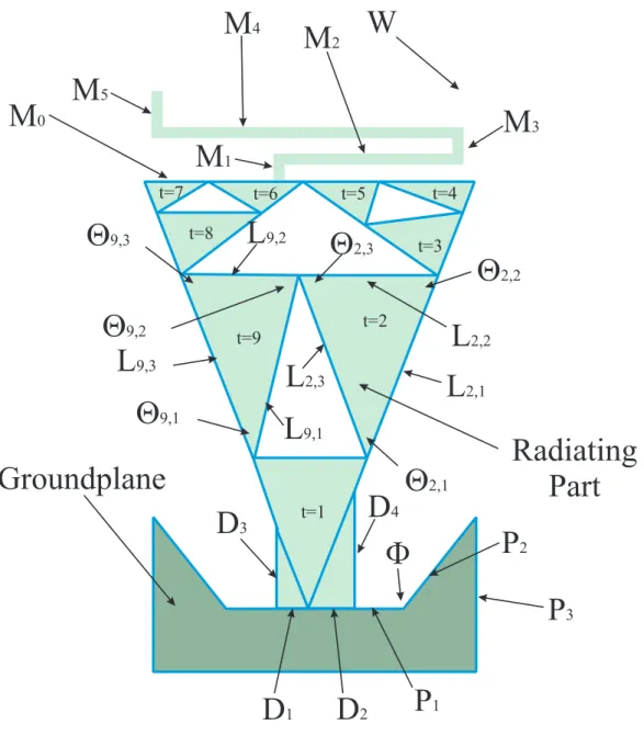
The reference geometry of the antenna is shown in Fig. 1. It consists of a Meander-like shape
connected to the top of a Sierpinski-like structure, a rectangular feedline, and the groundplane.
The Meander curve is identified by a set of NM = 7 real parameters {M0, ..., M5; W }, where
M0 is the distance between the upper-left corner of the Sierpinski-like structure and the con-nection point, Mi, i = 0, ..., 5 indicates the length of the i-th segment, while W is the curve
width. As regards the Sierpinski-like shape, Ls1,s2 andΘs1,s2 are the s2-th side and angle, re-spectively, of the s1-th triangle of the radiating part (Fig. 1) being s1 = 1, ..., 9 and s2 = 1, 2, 3. Moreover, the remaining descriptors of the “radiating part” are{D1, ..., D4}, while the ground-plane parameters are {P1, ..., P3; Φ}. Then, each antenna design is univocally identified by the following vector
ξ = {M0, ..., M5; W ; Ls1,s2; Θs1,s2; s1 = 1, ..., 9, s2 = 1, ..., 3; D1, ..., D4; P1, ..., P3; Φ} . (1)
Starting from the reference geometry, the three-band antenna has been synthesized by means of a PSO-based strategy aimed at varying the descriptive geometrical parameters in (1) to fit the design requirements. More in detail,a swarm of Q= 6 particles has been randomly initialized
and the position of each particle within the solution space corresponds to a trial antenna
mod-eled with a hybrid pre-fractal generator. The electric performances of each trial solution are estimated using a method of moment (MoM) electromagnetic simulator [29] and its matching with the project constraints is evaluated by computing an index of “goodness of the solution” (orcost functionΩ) proportional to the differences between simulated electric/radiation features (i.e., VSWR and gain values) and requirements
Ω (ξ) = ΩBand(ξ) + ΩRej(ξ) + Ωθ(ξ) (2)
where ΩBand(ξ) is the term related to the working frequencies, ΩRej(ξ) refers to the regions where a stopband behavior is required, and Ωθ(ξ) is concerned with the radiation pattern re-quirement. More specifically, the first term in (2) is given by
ΩBand(ξ) = X i max ( 0,V SW R(fi) − V SW RBand V SW RBand ) (3)
where i ∈ {GSM900, GSM1800, UMT S} and V SW RBand = 2.0. Moreover, a minimum value of V SW RRej = 5.0 is required at the two intermediate frequencies fR1 = 1350 MHz and fR2 = 2000 MHz in order to force the three-band behavior. This is taken into account by the second term of (2)
ΩRej(ξ) = X j max ( 0,V SW RRej− V SW R (fj) V SW RRej ) (4)
where j ∈ {R1, R2}. The last term
Ωθ(ξ) = X i max ( 0,θ−3dB − MLW (fi) θ−3dB ) (5)
ensures the synthesized radiation patterns having a main lobe width M LW greater than θ−3dB
As far as the behavior of the optimization process is concerned, the PSO logic [23] iteratively
updates the position of each particle (i.e., a trial solution) of the swarm on the basis of the
compliance with the project constraints “measured” in terms of values of the cost function (2).
The PSO iterative loop ends when the maximum number of K = 200 iterations is reached or
when the value of the fitness function Ω decreases below the convergence threshold ηconv =
10−3. As regards the PSO setup, the control parameters have been set to C
1 = C2 = 2.0 and
w= 0.4 [24].
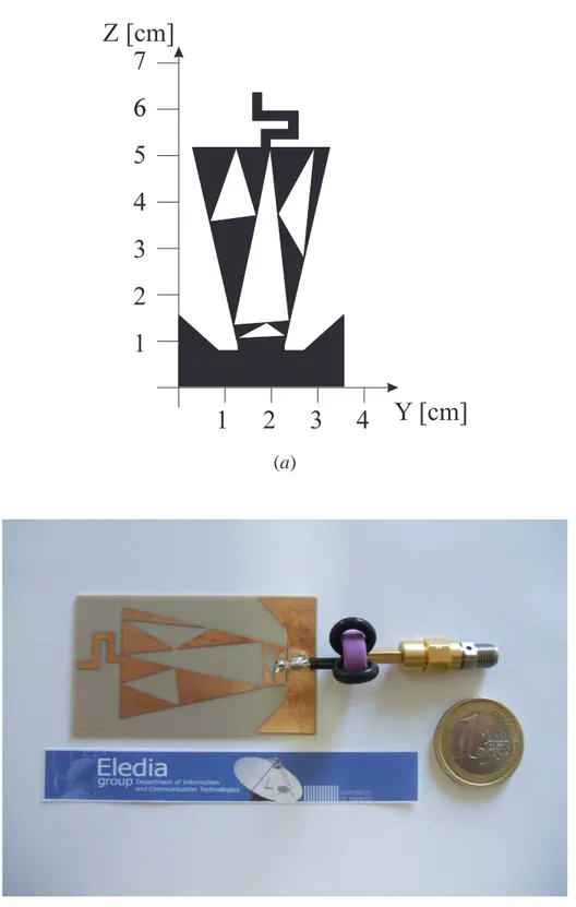
At the convergence (k = 101), the result of the optimization is the antenna structure shown in Fig. 2(a). As it can be noticed, it matches the dimension constraints occupying an area of
67.2 × 36.5 mm2. Moreover, it is worth to point out that the synthesized antenna turns out to be about 20% shorter than a standard quarter-wave monopole resonating atfGSM900= 890 MHz.
3
Numerical and Experimental Validation
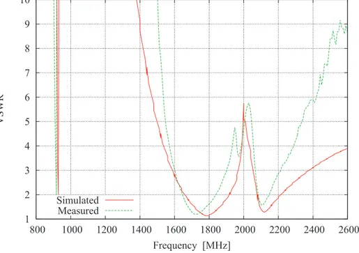
On the basis of the synthesized geometry, the antenna prototype in Fig. 2(b) has been built and fed by means of a coaxial cable through a SMA connector. The prototype has been experimentally tested in a semianechoic chamber, where the VSWR values at the input port and the radiation patterns have been measured. In order to prevent undesired radiations from the feeding coaxial cable, the antenna prototype has been equipped with a RF impedance to minimize the current flow along the external surface of the coaxial shield. Concerning the impedance matching and with reference to Fig. 3, a good agreement between simulations and measurements holds true as well as a suitable matching with the user-defined constraints. More in detail, the minimum VSWR values at the resonances are: V SW R(sim)GSM900 = 2.0 vs. V SW R(mis)GSM900 = 1.9; V SW R(sim)GSM1800 = 1.1 vs. V SW RGSM1800(mis) = 1.2; V SW R(sim)U M T S = 1.2
vs. V SW R(mis)U M T S = 1.5. On the other hand, the VSWR values at both fR1 and fR2 are greater
thanV SW RRej = 5.0assessing the three-band behavior of the synthesized antenna.
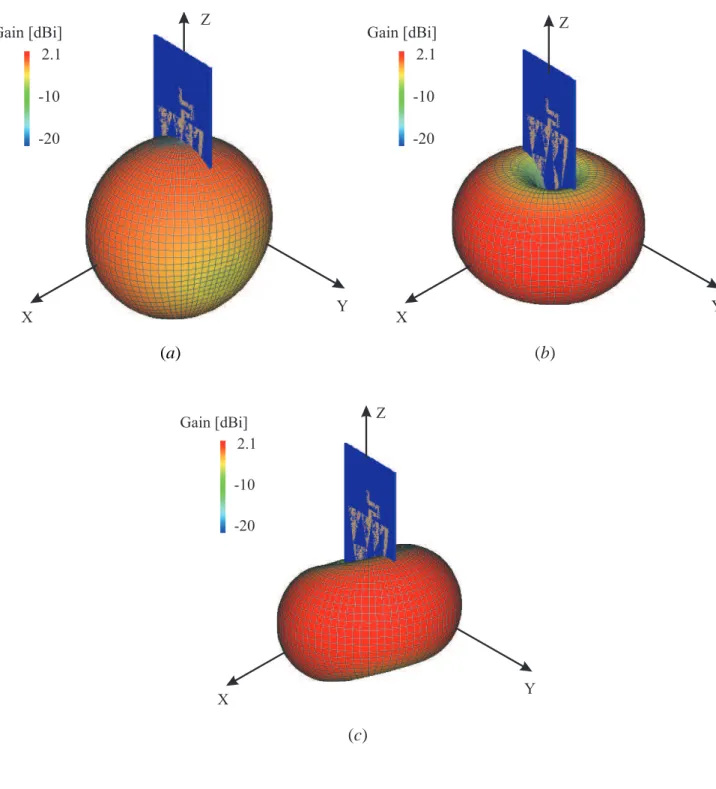
As regards the radiation properties, Figure 4 shows the simulated three-dimensional gain pat-terns at the three working frequencies. As expected, the antenna radiates like a classical monopole at the lowest frequency [Fig. 4(a)], while it behaves like a dipole radiator at fGSM1800 and
Meander-like shape used to tune the lowest resonance. Moreover, no additional lobes appear further assessing the multiband operation mode of the antenna. As a matter of fact, the presence of side lobes, as for wire monopoles or dipole antennas, usually indicates that the currents at the higher frequencies are overtones of the fundamental mode at the lowest one.
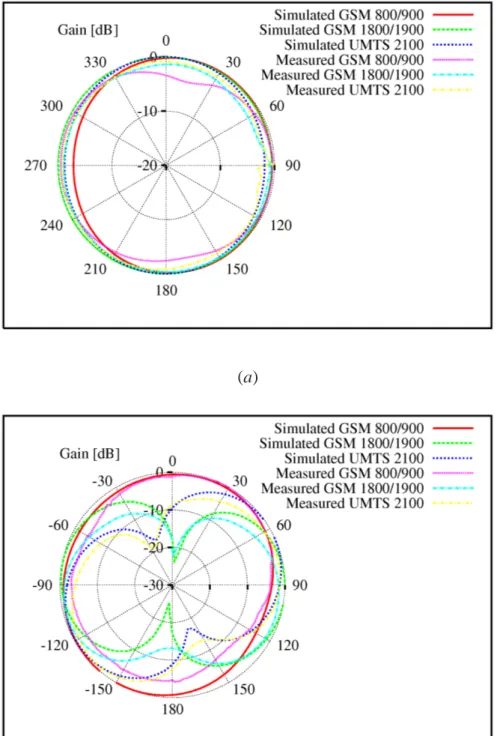
The pattern behavior of the antenna has been also experimentally validated through a set of
measurements probing the synthesized prototype along the horizontal (θ = 90o) and vertical
(φ = 90o) planes. The results of the comparison between simulated and measured gains are
shown in Fig. 5. Once again, there is a good agreement between simulations and measure-ments. The antenna presents an omnidirectional behavior along the horizontal plane, with a maximum variation over φ less than4 dB. As regards the vertical plane, the antenna shows an almost omnidirectional behavior at the lowest resonance, while it works almost like a dipole at fGSM1800and fU M T S. The main lobe widths along the vertical plane fit the project requirements
since M LWGSM900(sim) = 65o, M LW(sim)
GSM1800 = 75o, and M LW (sim)
U M T S = 69o.
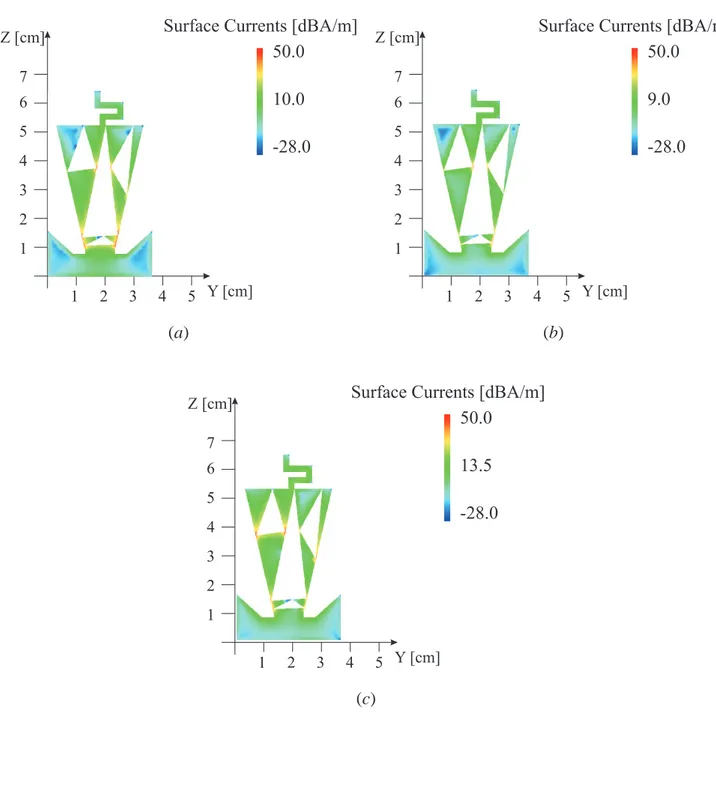
For completeness, the simulated surface current distributions are pictorially represented in Fig.
6 where both the “radiating part” and the “groundplane” of the antenna at the resonance
fre-quencies are reported. As expected, the currents concentrate in different regions of the structure
at the three different operating frequencies because of the multiband behavior unlike what it
happens for a wideband radiator. As an example, a greater amplitude of the surface current
density can be observed at fGSM900 in the bottom region of the “radiating” part of the antenna,
whereas the current distribution becomes more concentrated along the vertexes of the upper
triangles of the Sierpinski structure in the upper band (fU M T S).
4
Conclusions
In this paper, the synthesis of a three-band antenna with limited dimensions and suitable for the integration in a mobile device has been described. The reference geometry was a hybrid structure obtained by combining two different fractal shapes. The synthesis problem has been reformulated as an optimization one to determine the values of the descriptive parameters of the antenna geometry that comply with both electrical and geometrical requirements. The electrical performances of the synthesized antenna have been numerically and experimentally assessed to
assess the reliability and efficiency of the proposed implementation.
References
[1] Gianvittorio, J. P., and J. Rahmat-Samii, “Fractals antennas: a novel antenna miniaturiza-tion technique, and applicaminiaturiza-tions,” IEEE Antennas Propagat. Mag., Vol. 44, 20-36, 2002.
[2] Werner, D. H., and R. Mittra, Frontiers in electromagnetics. IEEE Press, Piscataway, 2000.
[3] Arrighetti, W., P. De Cupis, and G. Gerosa, “Electromagnetic radiation from moving frac-tal sources: a plane wave spectral approach,” Progress In Electromagnetics Research, Vol. PIER 58, 1-19, 2006.
[4] Hattori, H. T., “Fractal-like square lattices of air holes,” Progress In Electromagnetics Research Letters, Vol. 4, 9-16, 2008.
[5] Best, S. R., “A comparison of the resonant properties of small space-filling fractal anten-nas,” IEEE Antennas Wireless Propag. Lett., Vol. 2, 197-200, 2003.
[6] Baliarda, C. P., J. Romeu, and A. Cardama, “The Koch monopole: a small fractal antenna,” IEEE Trans. Antennas Propagat., Vol. 48, No. 11, 1773-1781, 2000.
[7] Sayem, A. T. M. and M. Ali, “Characteristics of a microstrip-fed miniature printed Hilbert slot antenna,” Progress In Electromagnetics Research, Vol. PIER 56, 1-18, 2006.
[8] R. Azaro, G. Boato, M. Donelli, D. Franceschini, A. Martini, and A. Massa, “Design of a miniaturized ISM-band fractal antenna,” Electron. Lett., Vol. 41, No.14, 9-10, 2005.
[9] R. Azaro, G. Boato, M. Donelli, and A. Massa, “Design of a prefractal monopolar antenna for 3.4-3.6 GHz Wi-Max band portable devices,” IEEE Antennas Wireless Propag. Lett., Vol. 5, 116-119, 2006.
[10] R. Azaro, M. Donelli, D. Franceschini, E. Zeni, and A. Massa, “Optimized synthesis of a miniaturized SARSAT band pre-fractal antenna,” IEEE Antennas Wireless Propag. Lett., Vol. 5, 116-119, 2006.
[11] Puente, C., J. Romeu, R. Pous, X. Garcia, and F. Benitez, “Fractal multiband antenna based on the Sierpinski gasket,” Electron. Lett., Vol. 32, No. 1, 1-2, 1996.
[12] Zhao, G., F.-S. Zhang, Y. Song, Z.-B. Weng, and Y.-C. Jiao, “Compact ring monopole antenna with double meander lines for 2.4/5 GHz dual-band operation,” Progress In Elec-tromagnetics Research, Vol. PIER 72, 187-194, 2007.
[13] Song, Y., Y.-C. Jiao, G. Zhao, and F.-S. Zhang, “Multiband CPW-FED triangle-shaped monopole antenna for wireless applications,” Progress In Electromagnetics Research, Vol. PIER 70, 329-336, 2007.
[14] Khan, S. N., J. Hu, J. Xiong, and S. He, “Circular fractal monopole antenna for low VSWR UWB applications,” Progress In Electromagnetics Research Letters, Vol. 1, 19-25, 2008.
[15] Puente, C., J. Romeu, R. Bartoleme, and R. Pous, “Perturbation of the Sierpinski antenna to allocate operating bands,” Electron. Lett., Vol. 32, No. 24, 2186-2188, 1996.
[16] Azaro, R., F. De Natale, M. Donelli, E. Zeni, and A. Massa, “Synthesis of a prefractal dual-band monopolar antenna for GPS applications,” IEEE Antennas Wireless Propag. Lett., Vol. 5, 361-364, 2006.
[17] Azaro, R., E. Zeni, T. Gazzini, R. Dallapiccola, and A. Massa, “Synthesis of a three-dimensional tri-band (L1-L2 GPS and Wi-Fi) pre-fractal tree antenna,” Microwave Optical Technol. Lett., Vol. 49, No. 9, 2114-2118, 2007.
[18] Zeni, E., R. Azaro, P. Rocca, and A. Massa, “Quad-band patch antenna for Galileo and Wi-Max services,” Electronic Lett., Vol. 43, No. 18, 960- 962, 2007.
[19] Lizzi, L., E. Viani, E. Zeni, and A. Massa, ”A DVBH/GSM/UMTS planar antenna for mul-timode wireless devices,” IEEE Antennas Wireless Propag. Lett., Vol. 8, 568-571, 2009.
[20] Azaro, R., F. Viani, L. Lizzi, E. Zeni, and A. Massa, “A monopolar quad-band antenna based on a Hilbert self-affine pre-fractal geometry,” IEEE Antennas Wireless Propag. Lett., Vol. 8, 177-180, 2009.
[21] Azaro, R., L. Debiasi, E. Zeni, M. Benedetti, P. Rocca, and A. Massa, “A hybrid prefrac-tal three-band antenna for multi-standard mobile wireless applications,” IEEE Antennas Wireless Propag. Lett., Vol. 8, 905-908, 2009.
[22] Mikki, S. M. and A. A. Kishk, “Physical theory for particle swarm optimization,” Progress In Electromagnetics Research, Vol. PIER 75, 171-207, 2007.
[23] Robinson, J., and Y. Rahmat-Samii, “Particle swarm optimization in electromagnetics,” IEEE Trans. Antennas Propagat., Vol. 52, No. 2, 397-407, 2004.
[24] M Donelli and A. Massa, ”A computational approach based on a particle swarm optimizer
for microwave imaging of two-dimensional dielectric scatterers,” IEEE Trans. Microwave
Theory Techn., vol. 53, pp. 1761-1776, 2005.
[25] Li, W. T. and X. W. Shi, “An improved particle swarm optimization algorithm for pattern synthesis of phased arrays,” Progress In Electromagnetics Research, Vol. PIER 82, 319-332, 2008.
[26] Lu, Z. B., A. Zhang, and X. Y. Hou, “Pattern synthesis of cylindrical conformal array by the modified particle swarm optimization,” Progress In Electromagnetics Research, Vol. PIER 79, 415-426, 2008.
[27] M. Donelli, R. Azaro, F. De Natale, and A. Massa, “An innovative computational approach
based on a particle swarm strategy for adaptive phased-arrays control,” IEEE Trans.
An-tennas Propagat., vol. 54, pp. 888-898, 2006.
[28] Azaro, R., F. De Natale, M. Donelli, E. Zeni, and A. Massa, “Optimized design of a multifunction/multi-band antenna for automotive rescue systems,” IEEE Trans. Antennas Propagat., Vol. 54, No. 2, 392-400, 2006.
[29] Harrington, R. F., Field Computation by Moment Methods, Robert E. Krieger Publishing Co., Malabar, 1987.
FIGURE CAPTIONS
• Figure 1. PSO-Based Antenna Synthesis Process - Reference antenna shape and un-knowns.
• Figure 2. Three-band hybrid prefractal antenna (Antenna configuration): (a) geometry and (b) prototype.
• Figure 3. Three-band hybrid prefractal antenna (Electrical parameters): VSWR values: _______ simulated, - - - measured.
• Figure 4. Three-band hybrid prefractal antenna (Radiation parameters). Simulated 3D radiation patterns - Gain at (a) fGSM900 = 890 MHz, (b) fGSM1800 = 1850 MHz, and
(c) fU M T S = 2045 MHz.
• Figure 5. Three-band hybrid prefractal antenna (Radiation parameters). Simulated vs. measured radiation patterns: (a) horizontal plane (θ = 90o) and (b) vertical plane (φ =
90o).
• Figure 6. Three-band hybrid prefractal antenna (Electrical parameters). Simulated surface currents at (a) fGSM900 = 890 MHz, (b) fGSM1800 = 1850 MHz, and (c)
L
2,1Q
2,1L
2,2Q
2,2L
2,3Q
2,3Q
9,1L
9,2Q
9,2L
9,3Q
9,3 t=2 t=3 t=5 t=4 t=6 t=7 t=8 t=9D
4D
3D
2M
0M
1M
2M
3M
4M
5W
L
9,1 t=1D
1P
1P
2P
3F
Groundplane
Radiating
Part
2
1
3
1
2
3
4
Y [cm]
Z [cm]
5
6
4
6
7
(a) (b)1 2 3 4 5 6 7 8 9 10 800 1000 1200 1400 1600 1800 2000 2200 2400 2600 VSWR Frequency [MHz] Simulated Measured
X Y Z Gain [dBi] 2.1 -20 -10 X Z Gain [dBi] 2.1 -20 -10 Y (a) (b) X Z Gain [dBi] 2.1 -20 -10 Y (c)
(a)
(b)
2 1 3 1 2 3 4 Y [cm] Z [cm] 5 6 4 5 7
Surface Currents [dBA/m] 50.0 -28.0 10.0 2 1 3 1 2 3 4 Y [cm] Z [cm] 5 6 4 5 7
Surface Currents [dBA/m] 50.0 -28.0 9.0 (a) (b) 2 1 3 1 2 3 4 Y [cm] Z [cm] 5 6 4 5 7
Surface Currents [dBA/m] 50.0
-28.0 13.5
(c)