European Standards for Structural
Fire Design of Masonry Elements
2.1 Introduction
The parts of structural Eurocodes related to fire (in general parts 1-2) consider specific aspects of passive fire protection in terms of the design of structural elements or entire structures in the presence of loads concurrent with the fire, and the limitation of the spread of the fire itself, where relevant. Essentially, the event "fire" represents one of the possible "loads" for the building, with the difference that it can change the resistance and the mechanical properties of materials, introducing also further deformations.
The performance levels may be specified in relation to classify nominal fire resistance (standard fire resistance), generally provided in the national fire
regulations, or, if allowed by them, referring to the engineering of fire safety for the evaluation of active and/or passive protection devices.
Requirements for the possible installation and maintenance of sprinkler systems, the conditions for the use of compartmentalized buildings and areas, or the use of approved insulating materials and coating, including their maintenance, are not provided in the Eurocodes because subjected to specifications by the competent national authority.
Numerical values for partial factors and other reliability elements are provided in the form of recommended values that ensure an acceptable level of safety. They have been selected assuming that an appropriate level of quality of works and quality management has been made.
The complete analytical design process for fire-resistant structures proposed in the Eurocodes consider the behavior of the structural system at elevated temperatures, the potential flow of heat to which the structure is exposed, and the positive effect of active and passive safety systems; the uncertainties associated with these aspects and the importance of the structure, in terms of the consequences of the collapse, are also considered.
Currently, a calculation procedure can be performed to determine an adequate performance, which includes several of the required parameters, and to demonstrate that the structure or its components provide a satisfactory performance in a real fire situation.
However, where the procedure is based on the nominal fire (normalized), the classification system, which draws particular periods of fire resistance, consider (although not explicitly) performance and the uncertainties described above. The application of the Part 1-2 of Eurocodes provides two alternative design processes which are illustrated in Figure 2.1. The prescriptive rules and the performance-based approach are identified. In the former the nominal fire is used to generate the thermal actions, while the latter refers to thermal actions based on physical and chemical parameters.
2.2 Performance requirement
2.2.1 General rules
When mechanical resistance R is required, structures must be designed and constructed in order to maintain their load-bearing functions during the exposure to fire.
If partitioning is required, the elements constituting the borders of each fire compartment, including the joints, shall be designed and constructed so that they maintain their functions during exposure to fire; in other terms:
the crisis for the loss of integrity E should be avoided in order to prevent the passage of flames and hot gases through the element bordering the compartment, and to prevent the occurrence of flames on the unexposed side;
the crisis to loss of insulation I should be avoided in order to limit the temperature increases on the unexposed face, without preset limits;
the resistance to mechanical impacts M must be guaranteed, when required;
the limitation of the temperature increase due to radiation must be ensured on the unexposed face, when required.
The effect of the deformations produced by the variation of temperature must be considered if the design criteria for the compartment elements or protection devices require it for the analysis and assessment of the load-bearing walls. Such deformations can be, however, neglected when the compartment elements must satisfy the performance requirements related to nominal fire.
2.2.2 Exposure to nominal fire
For the nominal fire exposure, the elements must be in accordance with the criteria R, E, I and M in relation to their function, as follows:
- Load-bearing only criterion R
- Separating only criteria EI
- Separating and load-bearing criteria REI
- Load-bearing, separating and mechanical impact criteria REI-M
- Separating and mechanical impact criteria EI-M
The criterion R is satisfied when the load-bearing function of a structural element is maintained throughout the required exposure time to nominal fire. The criterion
I, instead, is considered satisfied when the average temperature and the maximum
one at any point of the unexposed face do not rise by more than respectively 140°C and 180°C. As regards to the criterion E, it is verified when the passage of flame and hot gases is prevented.
When an element of vertical separation, with or without load-bearing function, require mechanical impact resistance (criterion M), it must be verified to the application of a horizontal concentrated load specified in EN 1363-2 [22].
As regards to the exposure to nominal external fire, the same criteria mentioned above are valid.
2.2.3 Exposure to parametric fire
The assessment of the load-bearing capacity function, in case of parametric fire, is satisfied when the collapse is not reached for the prescribed period of time considering the complete duration of the fire, including the cooling phase.
Instead, the assessment of the separation function, in reference to the criterion of isolation I, is satisfied if the following conditions are detected: the average temperature of the unexposed face does not exceed 140°C and the maximum one at any point 180°C, in the instant corresponding to the maximum of the temperature-time parametric curve; the average temperature and the maximum one of the unexposed face do not rise by more than respectively 180°C and 220°C, for the required period of time, considering also the cooling phase of the temperature-time curve.
2.3 Design value of material properties
The design values of the mechanical properties (strength and deformation) of materials, Xd,fi, are defined as follows:
, , k d fi M fi k X X , (2.1)
where Xk is the characteristic value of the generic mechanical property at room temperature given in EN 1996-1-1 [23], kθ is the reduction factor of the mechanical property value in function of the material temperature, and it can be expressed as:
, k k X k X , (2.2)
γM,fi is the partial safety factor for material properties, in the fire situation, the value of which must be specified in the national annex, but recommended by EN 1996-1-2 [1] to be equal to 1.0 for the mechanical and thermal properties. Xk,θ is the characteristic value of the material property at the temperature θ.
If an increase of mechanical properties is to the disadvantage of the safety, the expression (2.1) can be defined as:
, , ,
d fi M fi k
X X . (2.3)
The part 1-2 of Eurocode 6 [1] is applied to the materials belonging to groups 1, 2, 3 and 4 as defined in section 3.1.1 of part 1-1, which are summarized in Table 2.1. In addition, it’s possible to use the units belonging to the group 1S which includes those blocks that have a volume percentage of voids of less than 5% and which can be provided with recesses or grooves filled in the finished wall configuration. With regard to the mortar, the requirements are the same as those of EN 1996-1-1 [23].
Group 1 (all materials)
Group 2 Group 3 Group 4 Units Vertical holes Horizontal
holes Volume of all holes (% of the gross volume) ≤ 25 Clay > 25; ≤ 55 ≥ 25; ≤ 70 ≥ 25; ≤ 70 Calcium
Silicate > 25; ≤ 55 Not used Not used Concrete > 25; ≤ 60 > 25; ≤ 70 > 25; ≤ 70 Volume of any hole (% of the gross volume) ≤ 25 Clay each of multiple holes ≤ 2 gripholes up to a total of 12.5 each of multiple holes ≤ 2 gripholes up to a total of 12.5 each of multiple holes ≤ 30 Calcium Silicate each of multiple holes ≤ 15 gripholes up to a total of 30
Not used Not used
Concrete each of multiple holes ≤ 30 gripholes up to a total of 30 each of multiple holes ≤ 30 gripholes up to a total of 30 each of ultiple holes ≤ 25 Declared values of thickness of webs and shells (mm) No requirement
web shell web shell web shell
Clay ≥ 5 ≥ 8 ≥ 3 ≥ 6 ≥ 5 ≥ 6
Calcium
Silicate ≥ 5 ≥ 10 Not used Not used Concrete ≥ 15 ≥ 18 ≥ 15 ≥ 15 ≥ 20 ≥ 20 Declared value of combined thickness a of webs and shells (% of the overall width) No requirement Clay ≥ 16 ≥ 12 ≥ 12 Calcium
Silicate ≥ 20 Not used Not used
Concrete ≥ 18 ≥ 15 ≥ 45
2.4 Analysis and assessment methods
2.4.1 General rules
The model of the structural system adopted for the assessments to fire exposure should reflect the behavior and performance required for the constructions subjected to design fire action.
The analysis can be carried out using one of the following methodologies:
Experimental tests on structure or elements,
Tabular data,
Analysis of elements,
Analysis of parts of the structure,
Analysis of entire structure,
in compliance with the criteria summarized in Fig 2.1. The assessment must be on the time domain:
, , fi d fi requ t t , (2.4) or strength domain: , , , , fi d t fi d t R E , (2.5) or temperature domain: , d cr d , (2.6)
where tfi,d is the design value of the resistance to fire, tfi,requ is the required exposure time , Rfi,d,t is the design value of the element strength in case of fire at
the time t, Efi,d,t is the design value of the relevant effects of the actions in case of fire at the time t, Θd is the design value of the material temperature and Θcr,d is the design value of the critical temperature of the material.
The structural analysis must be carried out according to the general criteria indicated in EN 1990 [24]; when requesting a nominal exposure assessment, it is enough to carry out an analysis based on the structural elements, considering that the data tabulated in the Appendix B of EN 1996-1-2 [1] are relative to the nominal temperature-time curve defined in accordance to EN 1363-1 [25] as:
10
20 345 log (8 1)
g t C
, (2.7)
where Θg is the gas temperature inside the fire compartment [°C] and t is the time of exposure [min].
The alternative method of design based on experimental tests of fire resistance may be supported by data obtained from computational analysis.
2.4.2 Analysis of the structural elements
In order to obtain the effects of actions Efi,d,t during exposure to fire, the mechanical actions must be combined according to EN 1990 [24], which offers the following combination formula for exceptional design situations:
, ; ; ; 1,1 2,1 ,1;2, ,
1; 1
d k j d k i k i
E E G P A or Q Q j i , (2.8)
which can be placed in the form:
, 1,1 2,1 ,1 2, , 1 1 " " " " " " " "
d k j d k i k i j i E G P A or Q Q , (2.9)where Ad is the indirect actions due to fire exposure.
The Italian Ministerial Decree of January 14th, 2008 [26] recommends the use of the quasi-permanent value ψ2,1Q1 instead of frequent one ψ1,1Q1.
In this context, it is not necessary to consider explicitly the indirect actions due to fire, so the effects can be determined by analyzing the structure subjected to the combined actions according to (2.8) or (2.9), for t equal to 0 only; these effects, which are denoted by Efi,d, can be considered constant throughout the duration of exposure to fire.
In addition, as a further simplification, the effects of actions can be deduced from those of persistent or transient situations, combined according to the expression:
, , ; ; ,1 ,1; ,1 0, ,
1; 1d Sd G j k j P Q k Q i k i
E E G P Q Q j i , (2.10)
which can be put in the form:
, , ,1 ,1 ,1 0, , 1 1 " " " " " " d G j k j P Q k Q i k i j i E G P Q Q
, (2.11)otherwise, the less favourable of the following expressions can be considered:
, , ,1 0,1 ,1 ,1 0, , 1 1 , , ,1 ,1 ,1 0, , 1 1 " " " " " " " " " " " " G j k j P Q k Q i k i j i j G j k j P Q k Q i k i j i G P Q Q G P Q Q
, (2.12)where ξj is a reduction factor for unfavourable permanent actions. Therefore, we have that:
, , ,
fi d t fi d fi d
where Ed is the design value of the effects related to the actions of the fundamental combination (2.8), (2.9) or (2.10) and ηfi is the reduction factor defined by the following expression:
,1 ,1 ,1 k fi k fi G k Q k G Q G Q , (2.14)
otherwise, considering the expressions (2.12), by the less value given by the following relations: ,1 ,1 0,1 ,1 k fi k fi G k Q k G Q G Q , (2.15) ,1 ,1 ,1 k fi k fi G k Q k G Q G Q . (2.16)
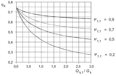
An example of the variation of the reduction factor ηfi in function of the load ratio
Qk,1/Gk for different values of ψfi placed equal to ψ1,1, is shown in the graph of Figure 2.2, where the following assumption are made: γGA = 1.00, γG = 1.35 e γQ = 1.50.
The curves related to the expressions (2.15) and (2.16) give values higher than those shown in Figure 2.2.
As a simplification, the recommended value of ηfi = 0.65 may be used, except for imposed load category E as given in EN 1990 [24] (areas of storage and industrial activity) for which the recommended value is 0.7.
Fig. 2.2:. Variation of the reduction factor ηfi in function of the load ratio Qk,1/Gk.
Only the effects produced by thermal expansion due to the gradients in the cross-sections should be considered, while the axial and the in-plane ones can be neglected.
The boundary conditions defined by the supports at the ends of each structural element can be assumed to be unalterable during the fire exposure.
Finally, the assessments can be carried out using methodologies based on tabular data or direct analysis with simplified or advanced calculation models, which are described in the following.
2.4.3 Analysis of part of the structure
The effects of actions on a part of the structure can be determined using the procedures specified in Figure 2.1, considering also the thermal expansion and the interaction with the other parts of the structure.
Referring to the part of the structure under study, methodologies of collapse due to exposure to fire, the temperature dependence of the material properties and the effective thickness variation of the elements must be evaluated.
Even in this case, the boundary conditions, the forces and moments explicated as reactions by restraints can be considered as unalterable during fire exposure.
2.4.4 Global analysis of the structure
When a global analysis of the structure is performed the following aspects must be taken into account: the failure modes of the structure, the temperature dependence of the material properties, the change in effective thickness of the members and the effects of indirect actions such as the thermal expansion during the fire exposure.
2.5 Design procedures
2.5.1 General rules
2.5.1.1 Wall types by function
For fire resistance, it is necessary to make a distinction between load-bearing and non-load bearing masonry walls and between separating and non-separating walls. The separating walls are used to prevent the propagation of fire from one room to another, so they are inherently exposed to fire on one facing only; examples of separating walls are those along the safe ways of evacuation, the walls of the stair wells, and the walls of the fire compartments.
The load-bearing masonry walls that do not fulfill the function of separation are to be considered subjected to fire on two or more sides, e.g. the walls that are located inside a fire compartment.
The external walls may be considered as separating walls or not, depending on the required performance, and if they have a length of less than 1.0m, however, must necessarily be considered as non-separating, for the possible presence of adjacent buildings.
In the case of walls with lintels above the vertical openings, the required fire resistance is not absolutely modified.
Elements with load-bearing function as transverse walls, slabs, beams, columns and frames, shall be provided with a fire resistance at least equal to that related to load-bearing walls.
Other instructions to consider in structural fire designing of masonry constructions are: the use of non-combustible material, the effects of thermal products by the presence of the adjacent constructions, the presence of columns and beams on the walls under study.
2.5.1.2 Cavity walls and untied walls with independent leaves
When the leaves of a cavity wall are of similar thickness and are subjected to loads of approximately equal intensity (Fig. 2.3), the fire resistance can be taken as that of a single leave wall having a thickness equal to the sum of those of the two leaves (only if combustible material is not present in the cavity).
Fig. 2.3:. Cavity wall with both leaves with load-bearing function; 1: connection system between the leaves or reinforcements of the horizontal mortar joints; 2: cavity partially or completely filled.
When only one leave has load-bearing function, the total fire resistance is higher than that for the single leave wall, if considered as independent (Fig. 2.4).
The fire resistance of a cavity wall with two non load-bearing leaves (Fig. 2.5) is given by the sum of the two relative resistances, with a maximum exposure time of 240 minutes.
Finally, for untied walls with independent leaves (Fig. 2.6), the fire resistance assessment must be carried out considering separately each of the two faces.
Fig. 2.4:. Cavity wall with only one leave with load-bearing function; 1: connection system between the leaves or reinforcements of the horizontal mortar joints; 2: cavity partially or completely filled.
Fig. 2.5:. Non load-bearing cavity wall; 1: connection system between the leaves or reinforcements of the horizontal mortar joints.
Fig. 2.6:. Untied wall with independent leaves (load-bearing or non load-bearing); 3: absence of connection system between the leaves.
2.5.1.3 Surface finishes
The fire resistance can be increased by the application on vertical surfaces of an appropriate finishing layer e.g. premix gypsum plaster according to EN 13279-1 [27] or plaster type LW or T as specified in EN 998-1 [28].
In case of cavity walls and untied walls with independent leaves, the works of surface finishing are required only on the exposed faces and not on the inner ones. An increase of resistance can also be given by the addition of another thin leave or by a further coating.
2.5.1.4 Additional requirements
The sheaths for waterproofing which are combustible can be neglected in the analysis phase, because it does not improve the fire resistance. Vice versa if this layer is non-combustible.
2.5.2 Assessment by experimental tests
For each type of masonry elements, the fire resistance can be obtained based on the results of experimental tests carried out according to the EN standards.
The tests should be performed taking into account that the behavior of the masonry at high temperatures depends on various factors, among which the most important are those which follow:
block material: clay, calcium silicate, autoclaved aerated concrete (AAC), dense or lightweight concrete, manufactured stone;
block type: solid or hollow (type of holes, percentage of formed voids), shell and web thickness;
mortar type: general purpose, joint thickness, weight;
relationship of the design loads to the design resistance of the wall;
wall slenderness;
eccentricity of the applied loads;
block density;
type of construction technique;
type of surface finishes;
Using the experimental tests assessment method, it is important to interpret the results by operating comparisons with the results of previous tests carried out in accordance with the criteria of EN 1363 [25 and 22], EN 1364-1 [29], EN 1365-1 [30], EN 1365-4 [31].
Particular attention should be paid to every difference introduced in the procedures described in these standards in evaluating the fire resistance of load-bearing walls, such as in restraints of the specimens: fixed ends, free, one fixed and the other free.
Even in tests for non load-bearing walls, changes in the restraint system can lead to not satisfactory experimental results, considering the test procedure specified in EN 1364-1 [29].
2.5.3 Assessment by tabular data
The assessment method of masonry walls using the tables is based on determining the minimum thickness tF to obtain the required time period of exposure to the fire
tfi,d, when the type of blocks, the related group and the density of the material are known.
It should be noted that the values of the minimum thickness shown in the tables is related only to fire resistance, while for other mechanical considerations we refer to EN 1996-1-1 [23].
In addition, the values given in the tables for load-bearing walls are valid for the total characteristic load Nk given by the following equation:
Rk k Glo N N , (2.17)
where α is the ratio between the applied load and design axial strength, which can conventionally assume values of 1.0 or 0.6, while NRk is the characteristic axial resistance load given by EN 1996-1-1 [23], which can be placed as:
Rk k
N f t. (2.18)
We observe that the tabular data were obtained from the elaboration of test results wherein γGlo was 3 to 5; fire tests, before the advent of partial safety factor, were subjected to the admissible load which was, approximately, the characteristic strength divided by the product of the partial factor for the action γF and that for the material γM.
The value of tF shown in the tables is to be considered related to the structural element in itself, without the presence of plasters or finishing works. The first line or couple of lines defines the resistance of masonry walls without adequate surface finishes; the values in parentheses in the second row or couple of rows are referred to walls with finishing works having a minimum thickness of 10mm on both the exposed sides.
Masonry elements with blocks of assigned size and unfilled vertical joints with a thickness of 2÷5mm, can be assessed using the tables related to the presence of finishes with a thickness of at least 1mm on at least one side. In similar cases the fire resistance is comparable to that given for walls without surface finishes. For masonry walls with vertical joints of thickness less than or equal to 2mm, any intervention of finish is not required: this type of panels can be assessed using the tables relating to the absence of surface finishes.
Finally, in the case of masonry with interlocking blocks or provided with grooves and having vertical joints without mortar and thickness less than 5mm, the assessment is based on the tables related to walls without surface finishes.
The tables referred to the various assessment criteria follow the schemes shown in Tab. 2.2, Tab. 2.3, Tab. 2.4, Tab. 2.5, Tab.2.6 and Tab. 2.7.
Materials
Minimum thickness tF [mm]
for fire resistance classification related to criteria EI for the exposure time tfi,d [min]
15 20 30 45 60 90 120 180 240 360 Block type, Mortar type,
Group and Density Wall thickness tF
Tab. 2.2: Minimum thickness for separating non load-bearing walls (Criteria EI) for the fire resistance classification.
Materials and load levels
Minimum thickness tF [mm]
for fire resistance classification related to criteria REI for the exposure time tfi,d [min]
15 20 30 45 60 90 120 180 240 360 Block type, Mortar type,
Group, Density, Load level α ≤ 1.0 and α ≤ 0.6
Wall thickness tF
Tab. 2.3: Minimum thickness for separating load-bearing single-leaf walls (Criteria REI) for the fire resistance classification.
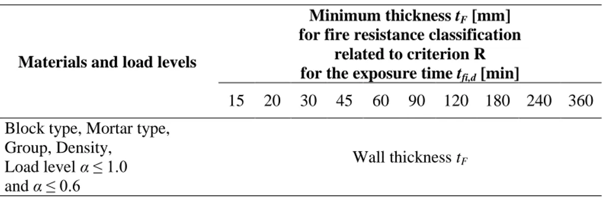
Materials and load levels
Minimum thickness tF [mm]
for fire resistance classification related to criterion R for the exposure time tfi,d [min]
15 20 30 45 60 90 120 180 240 360 Block type, Mortar type,
Group, Density, Load level α ≤ 1.0 and α ≤ 0.6
Wall thickness tF
Tab. 2.4: Minimum thickness for separating load-bearing single-leaf walls (Criterion R), having a length ≥ 1.0m for the fire resistance classification.
Materials and load levels Minimum wall thickness tF [mm] Minimum thickness tF [mm]
for fire resistance classification related to criterion R for the exposure time tfi,d [min]
15 20 30 45 60 90 120 180 240 360 Block type, Mortar type, Group, Density, Load level α ≤ 1.0 and α ≤ 0.6 tF Wall length lF
Tab.2.5: Minimum thickness for separating load-bearing single-leaf walls (Criterion R), having a length < 1.0m for the fire resistance classification.
Materials and load levels
Minimum thickness tF [mm]
for fire resistance classification related to criteria REI-M and EI-M
for the exposure time tfi,d [min]
15 20 30 45 60 90 120 180 240 360 Block type, Mortar type,
Group, Density, Load level α ≤ 1.0 and α ≤ 0.6
Wall thickness tF
Tab. 2.6: Minimum thickness for separating load-bearing single or double leaf walls (Criteria RM and EI-M) for the fire resistance classification.
Materials and load levels
Minimum thickness tF [mm]
for fire resistance classification related to criteria REI for the exposure time tfi,d [min]
15 20 30 45 60 90 120 180 240 360 Block type, Mortar type,
Group, Density, Load level α ≤ 1.0 and α ≤ 0.6
Wall thickness tF
Tab. 2.7: Minimum thickness for separating load-bearing double-leaf cavity walls with only one leaf loaded (Criteria REI) for the fire resistance classification.
It can be observed that the periods of fire resistance, from 15 to 360 minutes, given in previous tables cover the whole range given in the Commission Decision
of 3rd May 2000 in the Official Journal L133/26 dated 6th June 2000. It is stated, there, that the performance level for all or some classes or one class needs to be given. A Country may choose how many of the periods of fire resistance shown in the tables will be given in its National Annex, and for what range of materials and loading conditions.
Walls that include bed-joint reinforcement, according to EN 845-3 [32], may be considered as covered by these tables.
Finally, we underline that thicknesses of walls given in tables for non-loadbearing masonry, i.e. classification EI or EI-M, are only valid for walls having a height to thickness ratio less than 40.
2.5.4 Assessment by simple calculation models
In the method of assessment by simple calculation models, the load-bearing capacity of a generic masonry wall is determined by considering the boundary conditions and the residual cross-section, for predetermined periods of exposure to the nominal fire.
The fields of application of this method for the various materials are:
Clay : Groups 1 and 1S; compressive strength fb = 10 ÷ 40 N/mm2; gross density of dry material = 1000 ÷ 2000 kg/m3; mortar of general purpose.
Calcium silicate: Groups 1 and 1S; compressive strength fb = 10 ÷ 40 N/mm2; gross density of dry material = 1500 ÷ 2000 kg/m3; thin layer mortar.
Dense aggregate concrete: Group 1; compressive strength fb = 10 ÷ 40 N/mm2; gross density of dry material = 1500 ÷ 2000 kg/m3; mortar of general purpose.
Lightweight Concrete: Groups 1 and 1S; compressive strength fb = 4 ÷ 8 N/mm2; gross density of dry material = 600 ÷ (pumice) 1000 kg/m3; lightweight mortar.
Aerated Autoclaved Concrete: Group 1; compressive strength fb = 2 ÷ 6 N/mm2; gross density of dry material = 400 ÷ 700 kg/m3; mortar of general purpose and thin layer.
These limits relate to the simplified calculation methods calibrated on the results of experimental tests. However, the general principles of this method can be applied to masonry elements with blocks different from those in the above list. This is possible when the results of experimental tests for proper validation are available.
The correlation between the wall temperature and thermal expansion can be considered constant, and it is possible to use rules relating to the advanced calculation method for its determination.
The assessment procedure involves the following steps:
determination of the temperature profile for the required period of exposure in the cross section;
evaluation of the ineffective portion and the residual one, in the cross section;
determination of the load bearing capacity at the ultimate limit state related to residual cross section (Figures 2.7, 2.8 and 2.9);
checking that the calculated bearing capacity is higher than that required according to the respective load combination.
Assessment is by evaluating if the following inequality is satisfied or not:
2
,
Ed Rd fi
N N , (2.19)
where NEd is design axial force and NRd,fiθ2 is the design axial resistance given by:
2 1 1 2 2
,
Rd fi d d
N f A f A , (2.20)
where Φ is the strength reduction factor defined in EN 1996-1-1 [23], taking into account of the eccentricity eΔθ due to the temperature gradient, Aθ1 is the area of the cross section portion subjected to a temperature higher than θ1, Aθ2 is the area of the cross section portion subjected to a temperature between θ1 and θ2, θ1 is temperature up to which the cold strength of masonry may be used, θ2 is temperature above which the material has no residual strength, fdθ1 and fdθ2 are the compressive strength of the material at temperature respectively lower than θ1 and between θ1 and θ2.
The Annex C of the EN 1996-1-2 [1] places:
2 1
d d
f c f , (2.21)
Fig. 2.7:. Cross section of a column exposed to fire with real isotherms (1: boundary of original cross section; 2: isotherm for θ = θ2; 3: isotherm for θ = θ1)
Fig. 2.8:. Cross section of a column exposed to fire with idealized isotherms for simplified calculation models (1: boundary of original cross section; 2: isotherm for θ = θ2; 3: isotherm for θ = θ1)
In the simple calculation method, the eccentricity produced by the temperature gradient eΔθ may be assumed as equal to 0, when the fire is all around the structural element, otherwise it can be determined by the following expression:
2
2 20 1 8 20 ef t ef Fr h C e h t , (2.22)where hef is the effective wall height, αt is the coefficient of linear expansion at room temperature according to EN 1996-1-1 [23] and tFr is the thickness of the residual cross section subjected to temperatures lower than θ2.
The values of the temperatures θ1 and θ2 recommended by EN 1996-1-2 [1] are reported in Tab. 2.8.
Types of block and mortar (in absence of surface finishes)
Temperature [°C]
θ2 θ1
Clay blocks with mortar of general
purpose 600 100
Calcium silicate blocks with thin layer
of mortar 500 100
Lightweight aggregate concrete blocks
with mortar of general purpose 400 100
Dense aggregate concrete blocks with
mortar of general purpose 500 100
Aerated autoclaved concrete units with
thin layer of mortar 700 200
Tab. 2.8: Values of the temperatures θ1 and θ2.
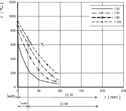
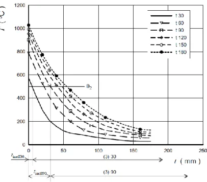
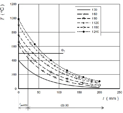
The temperature profile and the value above which the material is considered inefficient (Fig. 2.10), in function of the exposure period, should be determined by experimental tests. When this data are not available it’s possible to use the diagram shown in Fig. 2.11, Fig. 2.12, Fig. 2.13, Fig. 2.14, Fig. 2.15, Fig. 2.16 and Fig. 2.17, where T represents the temperature in °C, tineff30 is the wall
thickness which becomes inefficient after 30 minutes of exposure, tineff90 is that inefficient after 90 minutes, t is the thickness abscissa, (3) is the residual thickness where the number in parentheses represents the referred exposure period, e.g. (3) 30 corresponds to 30 minutes of exposure, (3) 60 to 60 minutes, (3) 90 to 90 minutes, (3) 120 to 120 minutes, etc.
Fig. 2.10:. Cross section of a separating wall exposed to fire with the corresponding profile of temperature (1: profile of temperature; 2: residual cross section area Aθ1+ Aθ2).
Fig. 2.11:. Clay unit masonry (dry material density = 1000 ÷ 2000 kg/m3
Fig. 2.12:. Calcium silicate unit masonry (dry material density = 1500 ÷ 2000 kg/m3): profiles of temperature.
Fig. 2.13:. Masonry with lightweight aggregate concrete units (dry material density = 600 ÷ 1000 kg/m3): profiles of temperature.
Fig. 2.14:. Masonry with dense aggregate concrete units (dry material density = 1500 ÷ 2000 kg/m3): profiles of temperature.
Fig. 2.15:. Masonry with autoclaved aerated concrete units (dry material density = 400 kg/m3): profiles of temperature.
Fig. 2.16:. Masonry with autoclaved aerated concrete units (dry material density = 500 kg/m3): profiles of temperature.
Fig. 2.17:. Masonry with autoclaved aerated concrete units (dry material density = 600 kg/m3): profiles of temperature.
2.5.5 Assessment by advanced calculation models 2.5.5.1 Introduction
The advanced calculation methods are based on the physical parameters of the materials, in order to obtain mathematical models that simulate the behaviour of the structure, or an element, in fire condition with an acceptable approximation level. Such models must be adopted for detecting the profiles of temperature into the structural elements (thermal analysis) and their mechanical behaviour (mechanical analysis).
In this kind of calculation method, all types of temperature-time curves defined in EN 1991-1-2 [33] can be adopted together to the available data related to the variation of the mechanical and thermal properties of the materials in function of temperature.
2.5.5.2 Thermal analysis
The advanced thermal analysis must be based on the principles and the hypothesis of the theory of the heat transfer. It must concern the thermal loads defined by temperature – time curves and the dependence from temperature of the thermal properties of the material: for the specific heat ca, the conducibility λa and the density , when the experimental data are not available, the diagrams shown in Fig. 18, Fig. 19, Fig. 20 and Fig. 21 may be used, where (1) represents the ratio between the property value at the temperature T and that at 20°C.
Fig. 2.18:. Clay unit masonry (dry material density = 900 ÷ 1200 kg/m3
): thermal properties in function of temperature.
Fig. 2.19:. Masonry with calcium silicate units (dry material density = 1600 ÷ 2000 kg/m3): thermal properties in function of temperature.
Fig. 2.20:. Masonry with lightweight aggregate concrete units (dry material density = 600 ÷ 1000 kg/m3
): thermal properties in function of temperature.
Fig. 2.21:. Masonry with aerated autoclaved concrete units (dry material density = 400 ÷ 600 kg/m3): thermal properties in function of temperature (data from corrigendum [34]).
2.5.5.3 Mechanical analysis
The advanced calculation methods provide mechanical analysis based on the theory and principles of structural mechanics, taking into account the changes of material properties due to the high temperature exposure.
The effects of the free thermal strain, load-induced one and those produced by temperature gradients must be detected: in a lot of cases the determination of the effects related to geometrical and material non linearity on the elements and/or entire structures must be determined.
Also the effects on boundary conditions must be evaluated in order to detect critical aspect related to possible failures for out-of-plane buckling phenomena. The assessment is on mechanical strength domain, evaluating if the inequality (2.5) is satisfied or not.
According to Annex D of EN 1996-1-2 [1], the diagrams related to the design free thermal strain and the design stress-strain curves in function of temperature for each mentioned material are shown in Figures 2.22, 2.23, 2.24, 2.25, 2.26, 2.27, 2.28 and 2.29, where εT is the strain in ‰, (1) represents the ratio between the property value at the temperature T and that at 20°C.
Fig. 2.22 Clay unit masonry (dry material density = 900 ÷ 1200 kg/m3; compressive strength f
b = 12 ÷ 20
N/mm2): εT in function of temperature.
Fig. 2.23:. Masonry of clay units of Group 1 (dry material density = 900 ÷ 1200 kg/m3; compressive strength fb = 12 ÷ 20 N/mm2): stress-strain parametric curves in function of temperature.
Fig. 2.24:. Masonry of calcium silicate units (dry material density = 1600 ÷ 2000 kg/m3; compressive strength fb = 12 ÷ 20 N/mm2): εT in function of temperature.
Fig. 2.25:. Masonry of calcium silicate units (dry material density = 1600 ÷ 2000 kg/m3; compressive strength fb = 12 ÷ 20 N/mm2): stress-strain parametric curves in function of temperature.
Fig. 2.26:. Masonry with lightweight aggregate concrete units (dry material density = 600 ÷ 1000 kg/m3
; compressive strength fb = 4 ÷ 6 N/mm
2
): εT in function of temperature.
Fig. 2.27:. Masonry with lightweight aggregate concrete units (dry material density = 600 ÷ 1000 kg/m3
; compressive strength fb = 4 ÷ 6 N/mm2): stress-strain parametric curves in function of temperature.
Fig. 2.28:. Masonry with aerated autoclaved concrete units (dry material density = 400 ÷ 600 kg/m3): ε
T in
function of temperature (data from corrigendum [34]).
Fig. 2.29:. Masonry with aerated autoclaved concrete units (dry material density = 400 ÷ 600 kg/m3): stress-strain parametric curves in function of temperature (data from corrigendum [34]).