Chapter 2 The assembly of hybrid microproducts
Chapter 2
The assembly of hybrid microproducts
2.1 The problem of high assembly costs
As mentioned in Chapter 1, the assembly phase is the main issue for the production of hybrid microproducts and usually the most expensive step. However, even if assembly is not as important as for hybrid microproducts, also silicon based ones need some assembly tasks to interface them with the macroworld [1].
Actually, assembly is considered the real bottleneck that limits the mass production and the diffusion of microproducts [2]. Unfortunately, traditional assembly strategies and equipment are usually not suitable in the assembly of microproducts because:
• surface forces become predominant with respect to mass related forces • tolerances become very narrow
• there are problems in measurement and control • components are delicate and fragile
• there is not a systematic approach to the design of hybrid microproducts
• methods, models and simulation tools specific for the microworld have not been developed enough.
2.1.1 Surface forces
When dimensions of objects become smaller than a few hundreds microns, surface forces are not negligible in comparison with gravitational and inertial forces [3][4]. Actually, gravitational forces are proportional to the object volume whereas adhesion forces are proportional to the object surface. Hence, in the microworld inertial forces scale down much faster than surface ones. The most significant surface forces in the range 1µm-1mm are Van der Waals’, surface tension, electrostatic ones. These forces depend on environmental conditions (such as humidity, temperature, surrounding medium), object features (surface, material) and relative motion between objects [5]. Since adhesion forces depend on many parameters which are difficult to be controlled, their evaluation is not exactly computable and it is impossible to get general results.
Van der Waals forces
Van der Waals forces are due to the instantaneous polarization of atoms and molecules by quantum mechanical effects. These forces are caused by various atomic interactions that are dipole orientation, excitation and dispersion effects. With the exception of few materials that have strong polarity (e.g. water and ammonium), the dispersion effect is dominant. This dispersion phenomenon causes a force also called
Microhandling devices for the assembly of Hybrid Microproducts
“London force” that arises from the instantaneous dipole generation of two atoms (also of different objects) that are set close [4].
Different strategies can be used to reduce that force. Since Van der Waals forces fall down rapidly when the distance between atoms increases, rough surfaces reduce significantly them. A second way to decrease Van der Waals forces is covering the contact surface of the objects with materials having proper Hamaker constant [4].
In nature, Van der Waals force is used by little animals as geckos to easily climb vertical walls and glass (Figure 1).
Figure 1: Van der Waals forces exerted among thousand cilia in the gecko’s feet and the wall allow the little animal to climb vertical walls.
Surface tension
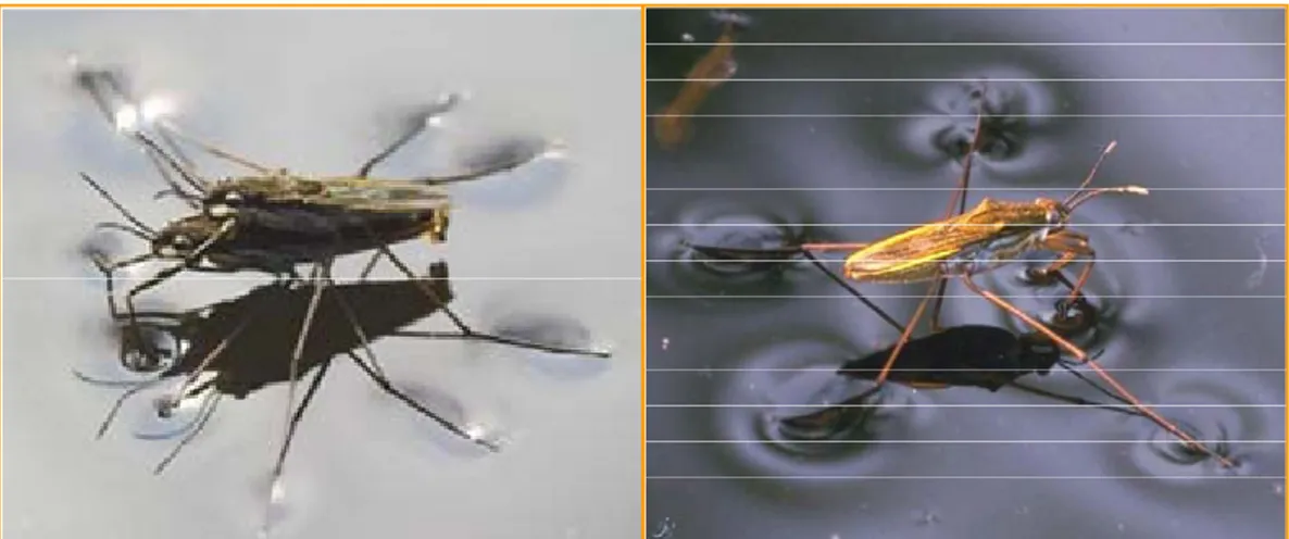
Surface tension forces originate from interaction of layers of absorbed moisture on two surfaces. Actually, the adsorption of moisture from the environment causes a thin film of water on the objects surfaces. If the objects are very close their films melt each other and the two objects are pulled together by the surface tension.
Adhesion forces increase with humidity level, contact surfaces, hydrophilic surfaces and contact times. Hence some attentions able to reduce drastically surface tension are dimples and tips on contact surfaces, hydrophobic coating (such as precious metals coating) and humidity controlled environment (with a level less than 9%).
Chapter 2 The assembly of hybrid microproducts
Figure 2: Surface tension allows insect to walk on water.
Electrostatic forces
Electrostatic forces are due to a charge generation (triboelectrification) or a charge transfer during contact. Triboelectrification is a charge generation due to friction between objects, while the charge transfer happens among objects of different potentials. Actually, if two objects are put in contact there is a charge flow between them in order to overcome this difference of potential. As obvious, the contact electrification is as lower as smaller is the potential difference between the two objects. If the gap between objects is very small (in the range of few nanometers) electron tunneling and field emission assure the transferring of charge, while for larger gaps air breakdown is needed.
Various strategies can be adopted to reduce electrostatic forces. The charge stored in objects is quickly drained off in grounded conductors while dielectric materials maintain a very high surface charge distribution. Even if the use of conductive materials reduces static charging effects, significant amount of charge can be stored if the objects are covered with insulator layers (such as native oxides). This stored charge is very difficult to be removed. If the two objects are both conductive, a surface roughness can reduce the stored charge in the dielectric interface by putting in contact the two conductors. Finally, the use of contact surface with tips increases the self discharge capability due to the high electric field strength at the tips.
The main drawback of adhesive forces is sticking effects that are very difficult to be controlled. As a consequence, adhesive forces can create problems both in grasping and releasing microobjects. Actually, these forces can be fruitfully used for picking parts but they can induce inaccurate placement [3] and more than one component could be grasped at the same time, while in the releasing stage parts tend to remain stuck to the gripper (Figure 3). These effects are reduced if the manipulation is carried out into a liquid medium (please refer to § 2.3.5).
Microhandling devices for the assembly of Hybrid Microproducts
Figure 3: Part sticks to the gripper (a); multiple grasping of spheres caused by adhesion (b).
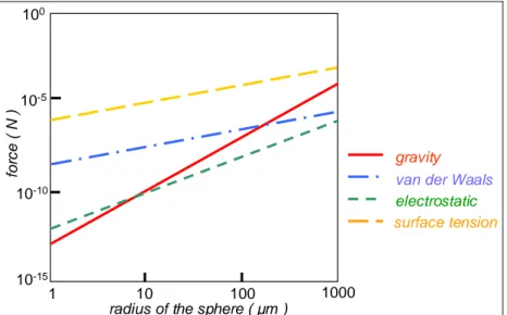
Figure 4 shows how the magnitude of gravity becomes smaller than other forces when the dimension of the object is less than one millimeter. So, traditional handling devices based on gravity are not suitable: for an accurate placement, adhesion forces should be an order of magnitude less than gravitational ones [6].
van der Waals electrostatic surface tension gravity 1000 100 10 1 10-15 10-10 10-5 100
radius of the sphere ( µm )
fo
rc
e
( N
)
Figure 4: Force between a silicon sphere and a flat plane [3].
The graph in Figure 4, has been obtained considering a charged spherical object in silicon and a half space that assimilates a gripper tip. The halfspace assumption simplifies calculations and permits to compute Van der Waals and electrostatic forces. Concerning to surface tension, it has been calculated considering hydrophilic surfaces and separation distance between the objects smaller than the object radius.
Chapter 2 The assembly of hybrid microproducts
Starting from these assumptions, the following general considerations are that the Van der Waals force overtakes gravity when the radius of the sphere is less than 100µm, but it is only significant for gaps less than about 100 nm. Unless objects are very smooth, it means that Van der Waals force will be significant only in the few points of contact. With regard to surface tension, it could be drastically reduced if working in dry environment. Hence, the electrostatic force that seems to be the least significant (it appears to prevent the manipulation of parts smaller than 10 um) is really the most important when handling is done in dry environment. In conclusion, it is important to mention that electrostatic forces can be active over ranges of object radius: thus it gives surface roughness little importance in reducing them. Finally, it is noteworthy that, since adhesion forces depends on the shape of the two objects brought in contact, they change considerably varying the shape of the gripper and the object to be grasped [5].
2.1.2 Tolerances and precision
Since in the assembly of hybrid microproducts the dimension of the handled microparts is usually in the range of micrometers up to few millimeters, the typical location accuracy is in the range of 0.1-10 µm (Figure 5). These accuracies are too narrow to be obtained by conventional assembly devices due to the joint backlash, the structural vibration etc.
<1 1 to 5 > 5 <10
10 to 100 >100
Figure 5: Component dimension and required accuracy in assembly (adapted from [30]).
2.1.3 Measurement and control
Conversely to the macroworld, where the direct hand coordination is intuitively established, in micro manipulation each piece of information requires an interface such as one or more microscopes. These microscopes usually have fixed orientation and limited performance in terms of magnification and depth of field as explained in the following paragraph.
Microhandling devices for the assembly of Hybrid Microproducts
Vision control
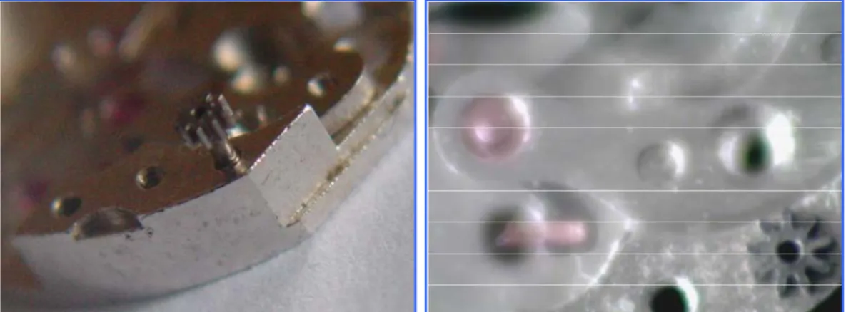
Since parts and components have features with dimensions up to few microns and close fits with tolerances in the nanometer range, a high magnification, resolution and definition are required to observe them. When parts become very little, it is required the increase of magnification and resolution to make possible their correct observation, so that it can be noticed that the observed area becomes small and the depth of field is small in comparison with the width of the observed area (Figure 6).
Figure 6: The depth of field is small in comparison with the width of observed area.
A possible solution for these problems is using mosaicing methods as shown in Figure 7: little areas of the object are observed with high resolution by means of many cameras, or with the same camera moving the object or the camera. Then, different images could be joined using different methods. However, the method is not so simple to be implemented in particular in case of on-line control for slow processing speeds. A solution reported in literature [8][9] that allows on-line control with a high resolution consists in the off line construction of the global image by mosaicing and an on-line in-lay of dynamical local images in this background. In this way the user has the global view with high resolution of the zone where the assembly task has to take place.
Other sources of errors are due to glare, reflection and other unwanted contaminations. Finally, the little distance between lenses and components often obstacles the handling of components by assembly devices.
Chapter 2 The assembly of hybrid microproducts 100µm 1 local image p a tte rn o f loca l i m a g e 2
Figure 7: Observed area and mosaicing method [9]. Force measurement
Another problem deals with force measurement. Often, in order to avoid damaging delicate components, forces used for handling microparts have to be less than few µN and are not so simple to be measured and controlled. Traditional sensors are, as obvious, not suitable to appraise so little forces and the required force measurement tools are very expensive. Often forces are inferred by optical examining of the deformation of tool tips by means of optical sensors.
2.1.4 Delicate and fragile components
When gravity overtakes adhesion forces, traditional handling devices are anyway difficult to be used because components are very delicate and fragile. Actually, systems as bowl feeders, vibratory feeders, belt conveyers etc., usually employed in conventional assembly, are not suitable to handle microcomponents.
Furthermore if microparts are damaged by the presence of dust (such as in case of lens or optical components), it is necessary to work under clean room conditions.
2.1.5 Standard, tolerances rules and systematic design
The approach to the design of hybrid microproducts is not still systematic, in terms of tolerancing, standard and design for microassembly.
Some efforts in this direction have been done by the Geometrical Product Specification (GPS), a project driven by the technical group ISO/TC213, and under the German Standard DIN 7186. The goal of the GPS project was the standardization in the field of surface properties, macro/micro geometry specifications, dimensional and geometrical tolerancing, verification principles, measuring equipment, calibration requirements. In the German Standard DIN 7186 (withdrawn), according to an established practice in microelectronic manufacturing, the worst tolerance is replaced by a statistical one.
Finally, with regard to the DFA (Design for Assembly) method, it is a well known technique in designing macroproducts while no systematic examples of extension to the
Microhandling devices for the assembly of Hybrid Microproducts
microworld exists. Engineering design perspective, such as well-defined axiomatic methods are still not widely adopted.
This lack of standardization and systematic rules in micro domain also gives problem in equipment design. Actually, it is one of the problems that forces equipment makers to waste time and resources on customizing automation solutions. Recently, some standards have been defined for micro-handling systems. In particular one of these is the DIN 32565 norm “Production equipment for microsystems” published in 2005. The standard specifies mechanical, electrical and optical interfaces between grippers and handling systems used in micromanipulation. This norm defines, also, the principal dimensions, tolerances, and designations for manual and automatic end-effectors.
2.1.6 Methods and models
Models and simulations methods are quite different from the macroworld and they are not completely developed for the microdomain. Hence, open problems still remain in force characterization and modelling as in simulations and in FEM tools.
2.2 The manual assembly of hybrid microproducts
Because of the reasons explained previously from § 2.1.1 to § 2.1.6, nowadays the assembly tasks of hybrid microproducts are usually performed by manual tools under a microscope. The manual approach is driven by the lack of affordable fully automated solutions with high reliability and high reproducibility. Actually, the advantage of manual strategy is its flexibility, which permits the assembly of various and complex structures with the same equipment. In a context of unpredictable market and middle low production quantity the versatility of microassembly devices is, as traditional assembly, an inevitable requirement. Conversely, the main drawbacks of this approach is to be a high time consuming activity for the difficulties in the assembly (adhesion forces, problems of visual depth of field and narrow tolerances etc.) and the trial and error approach. Furthermore, when high precision is required, the manual assembly becomes inadequate.
Due to manual approach, the assembly cost represents, at the present, up to the 80% of the total cost of hybrid microproducts.
Chapter 2 The assembly of hybrid microproducts
2.3 Alternative strategies for reducing costs
Different strategies are used as valid alternatives to manual assembly to reduce the cost of hybrid microproducts: • Teleoperated methods • Parallel assembly • Assembly Macrofactories • Assembly Microfactories • Submerged methods
In the following paragraph, the different strategies are considered and the advantages and the drawbacks of each one are highlighted. In particular, the microfactory approach, that seems to be the most promising for reducing the cost and the energy-space consumption, is deeply analyzed by means of an accurate report of the state of the art. Finally, an innovative approach for the automatic reconfigurable microfactory is proposed.
2.3.1 Teleoperated method
Telepresence is a possible means of performing precision tasks in microassembly. In teleoperated methods, the operator controls by means of sensors (generally a mixture of information in the forms of haptic, visual and audio feedback) the assembly tasks he carries out with various input devices (e.g. various joysticks, haptic devices, wearable gloves, foot pedals etc.)[10]. These input devices control the movement of the various handling equipment such as grippers, micropositiong systems, microrobots etc. allowing the manipulation and the assembly of microparts. According to Reinhart [10] and Others, the typical telepresence scenario is shown in Figure 8.
Microhandling devices for the assembly of Hybrid Microproducts
Interesting and effective teleoperated systems have been developed. Tanaka [11] has performed assembly tasks by a joystick that allows the use of many handling devices (grippers, positioning devices etc.) and controlled by a CCD camera. Reinhart and Others [10] have controlled the motion of a three axes cartesian kinematic system by means of a force-feedback joystick while the visual supervision of the assembly scenario is achieved through the two side-cameras. A similar approach is exploited in the “AFM based Micromanipulation System” described in [12], where an AFM manipulator was associated to a 3 DOF precise positioning system to pick and place microbjects in the dimension range of 5-50µm. A force-feedback joystick and two microscopes with cameras give the operator the control information. Kortschack and Others [13] have used some robots to hold, lift and transport cell in teleopearated experiments. The operator exploits a graphical interface on the user PC, a haptic interface and a feedback force joystick to teleopearate microrobots, positioning tables etc.
Even if the teleoperated assembly is able to improve the quality (in terms of positioning and joining precision) in comparison with pure manual assembly, it often remains a difficult task and a high time consuming activity that requires dexterous operators.
2.3.2 Parallel assembly
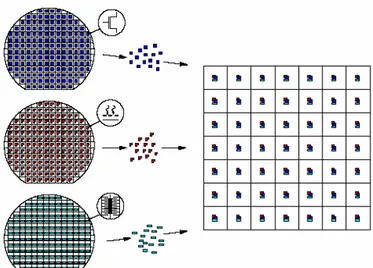
Contrary to serial assembly in which the parts are put together one by one, parallel methods permit to carry on a variety of assembly tasks for many components at the same time. Depending on whether the microparts are initially organized, the parallel assembly can be categorized as deterministic or stochastic-self assembly [1]. In the deterministic approach, arrays of microparts are transferred all together from a place to another one where an assembly task can be carried out simultaneously for all the components (e.g. in Figure 9 microscopic parts are arranged on various pallets that are then are pressed together: so the entire array is assembled).
Figure 9: Multiple micro-scale components (e.g. electronics or MEMS) are built in parallel then they are positioned and combined with other components on a hybrid pallet.
Chapter 2 The assembly of hybrid microproducts
In the self assembly strategy an initially random group of microparts is forced to arrange in a regular array (Figure 10) in order to be subsequently handled or assembled.
Initial condition Final condition
Binding sites Random group
of microobjects
Figure 10: Self assembly concept.
The basic idea of self assembly strategies is exploiting a structured potential field (gravitational, electrostatic etc.) to position components in the energy potential minima. In other words, self assembly is an energy minimization after considering the magnitude of all the forces involved in the process [14]. Often components are forced to be assembled together due to physical and chemical properties and their mutual interactions. Since the driving potential energy is usually not sufficient to overcome the surface forces, a source of random kinetic energy (e.g. ultrasonic vibration, air cushion) must be provided to the system [1]. An alternative to reduce contact forces and allow the components to be mobile is to carry out self assembly in a liquid environment. Finally, in order to let assembly within a reasonable period of time, any energy barrier must be as small as possible in comparison to the driving potential energy. The self assembly strategies can be carried out in liquid (wet processes) or not liquid (dry processes) environment.
In literature, many examples of stochastic parallel assembly exist. Yeh and Smith [15] have used the gravity in a liquid environment: microparts are fed by a liquid flow towards a tilted table where a series of pockets with the same shape of the parts are engraved. The parts fall down from the top and some of them remain trapped in the hollows while the others flow down and are recirculated. Hadley [16] also developed a similar fluidic self assembly method for integrating microblock containing MOS transistors to a glass substrate. Xiong and Others [17] made use of fluidic self assembly to position Gas light-emitting diodes on silicon substrates. They exploited hydrophobic-hydrophilic surface patterning and capillary forces of an adhesive liquid between binding sites located both in the objects and in the target areas. Hydrophobic-hydrophilic areas are also used by del Corral and Others [18] for parallel positioning and orienting of microparts. Böhringer and Others [19] made use of an electrostatic field with electrostatic traps. A parallel plate capacitor has apertures on the upper electrodes where there are fringing fields that induce polarization in neutral parts. So these parts are attracted to the apertures and get trapped there. Fantoni and Porta [20] exploited potential minima in a structured electrostatic field for sorting and positioning many metallic microspheres at the same time. Both Böhringer and Fantoni reduce adhesion forces between the platform and the
Microhandling devices for the assembly of Hybrid Microproducts
objects by means of a vibration platform. Cohn and Others [21] have used a slightly concave diaphragm that is agitated with a loudspeaker to self position many hexagonal parts with a diagonal of 1mm. Terfort and Others [22][23] demonstrated that millimeter-scale LED’s with operating electrical connections can be self positioned in water by complementary sculpting the mating surfaces and coating them with hydrophobic materials. Jacobs and Others [24] fabricated a cylindrical light emitting diode (LED) display using a patterned self assembly. The substrates presented patterned, solder-coated areas that acted both as receptors for the components of the device during its assembly and as electrical connections during its operation. The components were suspended in water and agitated gently. Minimization of the free energy of the solder-water interface provided the driving force for the assembly. The same approach has been used by O’Riordan and Others [25]: they utilized electric fields to direct gallium arsenide LEDs to assemble sites prepared onto silicon chips. A grid array exploiting fluidic self assembly was used by Fildes [26] and by Helmbrecht and Others [27] to the assembly of memory chips with an antenna to make an RFID tag. A fluidic self assembly using capillary, hydrophilic and hydrophobic force to assemble micromirrors onto micro-actuators was used by Srinivasan [28].
With regard to parallel assembly, Skidmore and Others [29] proposed an array of MEMS grippers packaged onto the same robotic arm to pick and place simultaneously an array of silicon micromachined mirrors into a substrate made of the same material.
In general, the main problem of the parallel and self assembly strategies is a very rigid structure with ad hoc devices designed for specific parts. So, the process becomes convenient only for a huge number of components to be treated. In addition, the self assembly that uses a stochastic approach gives the process a quite high time consumption and a statistical approach.
2.3.3 Macrofactory
In the assembly macrofactories, conventional machinery such as electronic assembly systems [30] and traditional robots [31][32] are adapted to the assembly of hybrid microproducts. Because of the lack of versatility, conventional assembly devices reduce the cost only in case of mass production. Furthermore, their use is possible only in case the required handling precision is not less than few microns. Actually, traditional robots have an accuracy that is mechanically limited for the presence of fabrication defects, friction, thermal expansion etc. These disturbing influences, negligible in the macroworld, play an important role in the microworld, making traditional robots not suitable for precision requirement in microassembly.
Other drawbacks are that the use of traditional machine and standard robots requires a high amount of energy and space consumption in comparison with the dimension of assembled products. It means big clean rooms and controlled environments to reduce sticking effect on microparts. Furthermore, when the dimension of the handled object is less than few hundreds microns, the use of traditional handling methods become impossible for the arising magnitude of surface forces.
Chapter 2 The assembly of hybrid microproducts
2.3.4 Microfactory
The microfactory is a miniaturization of a manufacturing and/or an assembly system. The aim of the miniaturization is reducing the ratio between the manufacture/assembly facilities and the microparts/microproducts obtained in terms of energy, material and space consumption. Hence, many devices have to work in a very little area with low energy consumption. Two categories of microfactories exist: the manufacturing-assembly microfactory one (where microparts are first manufactured then assembled) and the assembly microfactory (where only the assembly phase takes place).
With regard to the assembly microfactory [2], it should include the same devices of a traditional system: assembly, control devices and also proper strategies (Figure 11) in order to assure the complete and correct assembly of hybrid microproducts. The assembly tasks require both handling devices (such as sorting, feeding, grasping-releasing, positioning facilities) and joining systems (such as gluing, laser soldering and friction stir welding facilities). The on line-control (by means of vision systems and feed back sensors) must assure that each assembly task is correctly done, while assembly plans have to identify the most suitable assembly sequences. Finally, design for assembly strategies would allow a design of microproducts able to solve (or at least limit) assembly and control problems.
According to Fatikow and Rembold [33], a well conceived microassembly station must be able to automatically fulfill the following steps:
• preparation of the parts to be assembled • transportation of the parts
• positioning and fixing of the parts • connection of the parts
• testing and measuring the finished microsystems
MICROFACTORY Microassembly Stations / Devices Sensors Assembly sequences (CAPP) Control Microrobots Grippers Feeders and Trasport Devices Fixturing
Design for microassembly (DFµMA) Joining Station Measurement Process Control Product Control Micropositioning Systems Software
Microhandling devices for the assembly of Hybrid Microproducts
At the moment, only few automatic microfactories exist.
Some of them (e.g. Olympus Microfactory shown in Figure 12 and Seiko Processing and Microassembly system shown in Figure 13) have been developed by industries for manufacturing and assembling their products but they have a quite rigid structure with a product orientation.
A small number of assembly systems (e.g. those developed by Zyvex and Sysmelec shown, respectively, in Figure 14 and in Figure 15) are commercially available. These systems assure high submicron positioning accuracy and allow the use of various handling and joining techniques with low space consumption.
Many others microfactories are object of research projects. These assembly systems follow three main approaches:
1. single assembly area
2. moving carrier with components 3. cooperative microrobots
In case of single assembly area, there is only a region where the assembly takes place and the entire devices act in this workspace. It is what happens in the Desktop machining and assembly microfactory developed by Tanaka and shown in Figure 16, but this system seems to be more an evolution of teleassembly than automatic assembly systems. Other examples are the Assembly microfactory developed at Helsinki University of Technology (Figure 17), the Microassembly system developed at Karlsruhe Research center (Figure 18), the Microassembly and packaging System for microoptical devices developed at Fraunhofer Institute (Figure 19).
The second approach makes use of moving carriers loaded with the components to be assembled that move from an assembly station to another one. In each station, one or more assembly task is performed so that the microproduct is completely assembled after the last assembly station. The stations can be located around a rectangular workspace as in the MiniProd system developed by Fraunhofer Institute (Figure 20). In other cases the stations are positioned next a path which is covered by the mobile carrier (please refer to the microfactory developed within the PRIN Project 2006-2007 described in Chapter 5). Another solution is the one used in the Agile Assembly Architecture developed at Carnegie Mellon University (Figure 21): the carriers move freely on various platen tiles that can be flexible arranged to form different layout. In general, when the carrier moves freely the advantage is a better flexible capability and a low space consumption of the assembly system but difficulties in the positioning control and accuracy. Conversely, microfactories in which the carrier moves along a path show an easier control of the position and higher accuracy. In both cases a particular station layout would permit the assembly of a few microproducts: when the product features or the assembly tasks change considerably a new layout of modules should be set up.
In the latter methods (cooperative robots), a cluster of small mobile autonomous robots, generally equipped with onboard electronics for control and communication, cooperate to accomplish various microassembly tasks. This approach has been used in the microassembly systems developed in the Micron project (Figure 23) and in the Flexible
Chapter 2 The assembly of hybrid microproducts
microrobot-based microassembly station developed at the University of Karlsruhe (Figure 24).
Even if some of these microfactories show a quite flexible and reconfiguration capability and the “plug and produce” target is becoming a realistic option, several efforts are still required to reach a real complete, automatic and fast reconfigurable microfactory.
Some examples of assembly microfactories realized in the world are here shown. Microassembly systems developed by industries
The Olympus microfactory [38] (Figure 12) is a microsystem that can assemble a lens with a 1 mm external diameter, a micro CCD and a lens frame. These tasks are very difficult with conventional automatic assembly equipment. Handling technologies and image processing capabilities offer sure manipulation of microlenses. Backed by these capabilities, the system brings automation and greater accuracy in inserting a microlens and attaching it to a micro-CCD and lens frame. The system's miniaturization is suited to be installed on a clean bench and, because it is resistant to changes in the ambient temperature, positioning is precise and stable. It is much more cost-efficient than conventional equipment for the same tasks and productivity is boosted since the transport distance between processing steps is shorter.
Microproducts assembled:
• Lens with a 1 mm external diameter • Micro-CCD
• Lens frame
Components:
• Deep focus microscope • Parallel link micromanipulator
-miniaturized ultrasonic linear motor -elastic hinge with bending deformation • Parallel-link stage (6 DOF: 3 translations
and 3 rotations)
-6 links driven by an ultrasonic linear motor
Olympus microfactory
(Olympus optical Co.Ltd)
Foot print: 500mm x 350mm
Figure 12: The assembly Microfactory developed by Olimpus [38].
The microfactory system developed by Seiko Instruments [39][40] and shown in Figure 13 consists of three units: a processing, an assembling and a conveyance one. The dimension of the system is about the size of a desktop and can handle small parts of several grams in weight. The system can make the gear train, which includes a gear of sub-millimeter diameter. The gear is first made in the processing
Microhandling devices for the assembly of Hybrid Microproducts
unit and it is transported to the assembling unit by the conveyance devices to be assembled by micro-arms. Some other parts can be provided by the part-supply station to the assembling unit. The fabrication process of the gear train consists of many steps. First, a Cr substrate is etched and a sacrifice layer is formed. Next, the substrate is conveyed to the assembling unit and a pin of gear is assembled in it. The substrate is replaced in the processing unit and Ni is plated on it. After the sacrifice layer is etched in the processing unit, the gear with pin is conveyed for the assembling unit.
Components: Assembly unit
• Micro arm with two fingers: multi DOF and micron precise positioning
• Working tools (can be automatically attached to and detached from the tip of the micro-arm via an electromagnet)
- adhesive micro-application device - electromagnetic micro-chuck - vacuum chuck
Transport unit
a plane is fitted with 12,800 electromagnets. By switching the current among
electromagnets, the pallets equipped with permanent magnets can move in 2 DOF
Processing unit
• Electrochemical micromachining device can perform accurate electrochemical metal removal or addition with a
• Liquid feeding pump supplies liquids and coolants to electrochemical devices
Processing environment observer
• CCD camera (for controlling the permanent magnet on the transporting unit)
• environment aware device (a servo-actuator and a microball screw bring the environment aware device close to the surveyed object) • image guide (made from shape memory alloy
--SMA- allowing for multi DOF swivel)
Seiko Processing and Microassembly system (Seiko Instruments Inc.)
- Total size : 600 x 650 x 750 mm - Object size :<10mm
- Object weight :<2g
The microfactory
The transport unit
The working tools change system
Microproducts assembled:
• Swatch gears
Chapter 2 The assembly of hybrid microproducts
Microassembly systems commercially available
Zyvex A100 Assembly system (Figure 14) is a manipulation and assembly tool which can be used with an electron or with an optical microscope for the assembly of microscale components manufactured from various MEMS manufacturing techniques. This assembly system is equipped with Zyvex NanoEffector® Microgrippers.
Components:
• Two positioners
- The first one has 3 translational DOF (x, y, z) - The second one has 4 DOF (x, y, z, Ø) • Sample stage having 3 DOF (x, y, Ø) • Microgrippers (Zyvex NanoEffector): silicon
electrostatic actuated able to manipulate microcomponents in the range 1-500 µm) • NanoEffector Probes
• PC-based Control System
• Joystick or graphical user interface control
Possible applications:
• Microassembly operations
• Nanoparticle manipulation for analysis • Optical component manipulation: laser diodes
photo diodes, lenses, and fibers
A100 Assembly system (Zyvex)
Figure 14: The Microassembly System developed by Zyvex [34].
Sysmelec robot and automation, a manufacturer of advanced customized and standardized robotic equipments, has developed a complete range of machines allowing assembling and bonding of microsystems and optoelectronical microcomponents [35]. These machines (Figure 15) are:
• SMA 1000: high precision machine for assembly or bonding (assembly precision +/ − 2µm) with vision from the top of the component;
• SMB 1000: high precision machine (assembly precision +/
− 1µm) for flip chip bonding with vision from the top and from the bottom of the component;
• SMS 1000: submicron assembly or alignment machine (assembly precision +/ − 0.3 µm).
In particular the SMA 100 and SMB 1000 have been designed with a modular-open concept which allows the integration of many units. They can incorporate several devices in the same assembly cell as different adhesive dispensers, UV or thermal curing units, soldering/tacking equipment, feeders for wafers, Wafflepacks and Gel pack.
Microhandling devices for the assembly of Hybrid Microproducts
Components:
• Alimentation units (available solutions) - Gel-pak
- Waffle Pack - AUER Boats
- specific and multifunctional carriers • Positioning units
- Prepositioning unit: unit guided by
vision that allows a "rough" positioning (+/- 2 microns) components
- Active alignment unit: piezo manipulator working in relation with a light intensity analyser by means of a software • Joining units
- Dispensing of glue and on site curing - Laser welding
• Specific units
- cleaning of the components
- correction of the fibre orientation before the assembly
- bar code reading
- marking of good and bad components
Possible applications:
SMS 1000
active and fully automatic assembly of - micro-lens
- optical mono-modes fibres SMA 100
high precision assembly of small and very delicate components
Machines for microsystems assembly
(Sysmelec SA)
Chapter 2 The assembly of hybrid microproducts
Microfactories developed within research projects First approach: Single assembly area
The Mechanical Engineering Laboratory (MEL) of Japan developed a prototype desktop machining microfactory [11]. The microfactory (Figure 16), which will enable considerable savings in terms of energy, space and resources, is a downsized production system whose size is very small with respect to the dimensions of the products. Under manual control by means of a joystick and one push button, the operator is able to fabricate and assemble a miniature ball bearing.
Tasks performed:
• Manufacturing
1. The rotary shaft (d=100- 500µm) by the microlathe
2. The bearing housing by the milling machine 3. Punching out and bending of the top cover
with three jaws by the press machine
• Handling
1. Transporting of the microparts from the machining area to the assembly area using the micro transfer arm equipped with a negative pressure holding unit
• Assembling with the two-fingered hand
1. Picking and inserting of the balls into the bearing housing
2. Picking and inserting of the rotary shaft into the bearing housing
3. Picking and placing of the top cover onto the housing with balls
Microproducts assembled: Miniature ball
bearing
Components:
• Microlathe
• Miromilling machine • Micropress machine
• Microtransfer arms with 4 DOF
(3 of translation and 1 of rotation)
• Two-fingered microhand with 6 DOF
(each finger has 3 piezoelectric actuators and a parallel link mechanism with elastic hinges allowing 3 translational motions)
Desktop machining and assembly microfactory (developed by Mechanical
Engineering Laboratory [MEL], Japan)
- Volume: 625mmx490mmx380mm - Weight: 34 kg
- Power source: 100 V AC
Microhandling devices for the assembly of Hybrid Microproducts
In the Assembly microfactory developed at the Helsinki University of Technology [41][42] and shown in Figure 17, a software allows the microassembly system to operate in a manual mode, in a teleoperated mode with a joystick or in a automatic mode based on off-line programming. Moreover, bilateral gripping control is implemented based on a 1 DOF haptic device. The three microscopes provide good visual information of the workspace and enable the system to operate both large objects (larger than 1 mm) and small objects (as small as 5 µm). The platform demonstrations have considered the telemanipulated assembly of a three-piece cylindrical structure with minimum diameter of 10µm, the dispensing of micro droplets on microparts and the handling of single paper fibers.
Components:
Environmental control system
• Environmental chamber
• Automatic system to control temperature and humidity
Microassembly platform
GRIPPER
• Two grippers with piezoelectric tips, both grounded and provided with strain gauges: - a small one (8) for parts size under 100 µm (The microgripper is mounted on a piezoelectric
bender for z-axis displacement)
- a large one (9) for parts size until 3500 µm (The gripper is mounted on a motorized stage which has a stroke of 15 mm and resolution of 0.05 µm. The gripper and the motorized stage are mounted on a manual xy stage having a stroke of 25 mm for planar position alignment) POSITIONING TABLE (6)
• primary xy positioning stage: two commercial (6) motorized stages with a workspace of 15×15 mm and a resolution of 0.05µm
• secondary xy positioning stage two Micro Pulse System piezo ultrasonic stages GLUE DISPENSER
• Microdrop droplet glue dispenser with UV light source for curing
Vision system
• Two microscopes (1-3) with CCD video cameras (top view and side view) • Tube microscope (4) with motorized zoom
and focusing system (perspective view)
Control system
• Multifunctional real time microrobotic software using C++
Assembly Microfactory (Helsinki University
of Technology, Finland)
Chapter 2 The assembly of hybrid microproducts
The 4 DOF modular assembly system (Figure 18) developed at Karlsruhe Research center [33][43]has a planar positioning table above which an overhead manipulator and a stereo microscope with a CCD camera are located. The manipulator can move perpendicular to the positioning table and can be equipped with different grippers or end-effectors by an automated revolver change. All assembly parts are manually inserted into magazines and then placed in exactly defined positions on the planar table. The assembly steps are carried out semiautomatically in an interactive way: the operator obtains on a monitor, through the microscope with CCD camera, the visual information of the workspace and initiates the assembly step with a mouse click on a graphical interface. The microproduct assembled are Microoptic duplexers consisting of 0.9 mm spherical lenses, a 3x3x1 mm3 wavelength filter and a glass plate of 1x14x1mm3.
Microproducts assembled
Microoptic duplexers
Components:
Positioning system (accuracy 2 µm)
• a precise XY commercial table system (Kloche Nanotechnik)
• a manipulator moving along and rotating around Z axis
Gripper (revolver tool changer (1) with six tool position)
• Adhesion gripper (2) (using water to seize and center microcomponent) • Vacuum gripper (3) with force sensor in
3 axis and end effector adaptable to components geometry
• Two-finger gripper (4) piezo actuated (travel of gripper 1,2 mm)
Assembly technology
• Presses • Wedging • Splicing tapes
Vision control system
• Stereo microscope with CCD camera and digital image processing
Software Control
• engineering software with graphical interface
• image processing
Microassembly System (Karlsruhe
Institute for Applied Computer Science, Germany) working volume : 200 mm x 200 mm x 70 mm 3 4 1 2
Microhandling devices for the assembly of Hybrid Microproducts
Another flexible and modular robot system (Figure 19) has been developed at Fraunhofer Institute [44]. It allows the development and testing of complete assembly procedures. In particular, this assembly system is used for the determination and optimization of technology parameters, qualification of complex assembly cycles, assembly of prototypes and pilot lots and assembly of optical components.
Microproducts Assembled:
Microoptical systems
Components:
Microassembly and packaging System for microoptical devices
(Fraunhofer IOF, Germany)
Positioning systems
• XYZ-piezoactuator (resolution 1 nm, travel range ±50 µm)
• 6-DOF parallel robots (accuracy ±0.5 µm, resolution 100 nm, travel range ±5 mm)
• 4-DOF SCARA robot (accuracy ±5 µm, travel range 150x100x30 mm³ )
6-DOF articulated arm robot (accuracy ±30 µm, workspace Ø 600 mm)
Joining tools
•Solder laser
•Adhesive dosage systems
Measurement and control
• LabVIEW®user interface and
programming modules
• Multi-framegrabber for up to 6 cameras • LabVIEW®image processing
Handling tools: task specific
microgrippers (mechanical and vacuum(2) on a revolver turret (1))
Figure 19: Microassembly and packaging System for microoptical system developed at Fraunhofer Institute [44].
Second approach: Moving carrier with components
The assembly system developed within the MINIPROD project [45][46] is based on small, compact process and assembly modules which are mounted on a product-neutral platform in “plug and produce” mode using standardized interfaces (Figure 20). Among the range of modules available, the user is able to select the modules required for the specific application and can thus assemble a miniaturized product. A virtual module kit system allows the operators to combine the modules in a virtual environment in order to simulate the microassembly system before proceeding to its physical construction and
Chapter 2 The assembly of hybrid microproducts
assembly carrying out. The interfaces of the modules and material flow components are designed in such a simple way that any change in the manufacturing concept can be realized in a short space of time. Energy, media and information can be all transmitted via integrated and configurable interfaces.
Microproduct assembled: MINI LASER DIODE (3) Potential Microproducts assembled: miniaturized magnetic
valves, mini encoders, microswitches, microgears, micromotors, minimally invasive surgery devices, components for mobile radio devices, glass fiber switches.
Components:
• Planar motor (0.6 m X 0.4m): feeding of parts and flow of
materials among the process stations
• Transport modules: several couriers transport the
microcomponents and move on a friction-free air bearing reaching a positioning accuracy of 20 µm (controlled mode) or 200 nm (using magnetic sensors)
• Assembly modules: modules for handling, micro-screwing
(2) and micro-bonding (the basis for the modules is formed by pneumatically or electrically-driven 2 axial precision kinematics)
• Control architecture: each module owing its JAVA controller
and linked to other ones by an industrial Ethernet
working area : 800 mm x 800 mm
3
200 100
2
MiniProd system (Fraunhofer Institute for manufacturing Engineering and Automation
with industrial partners)
Microhandling devices for the assembly of Hybrid Microproducts
The Agile Assembly Architecture (AAA)developed at Carnegie Mellon University [36][37] is an overarching framework intended to provide manufacturers with the ability to rapidly design, program, and deploy precision automated assembly systems. AAA (Figure 21) has two parts: i(i) a distributed collection of computational/physical robotic agents
comprising a “minifactory,” and (ii) a comprehensive software Interface Tool.Minifactory is a distributed collection of cooperating intelligent robotic agents that perform microassembly and related operations. The AAA Interface Tool provides a centralized viewpoint for the design, programming, debugging and monitoring of a virtual or real minifactory.
Components of the MINIFACTORY
Structure
• Base Units: to supply services to the various modular agents
• Platen tiles (the factory “floor”): arrays of ferromagnetic posts that provide electromagnetic reaction forces and position references for courier • Bridges: modular structural bridges to
accommodate various manipulators Handling
• courier agents: they travel on air bearing and are based on commercial planar motors retrofitted with 3-DOF ac magnetic position sensors (accuracy 0.2 µm). Couriers are also equipped with optical sensors that enable them to precisely locate (resolution 0.15 µm)LED beacons incorporated into manipulators. They transport products through the factory and participate in assembly operations. • manipulator agents: they have rotational
and translational DOF for picking and placing parts.
• end effectors: they are attached to the end of manipulators through a quick-change interface with electrical and pneumatic connections. A typical modular end-effector has a camera, an illuminator, a force sensor, one or more LED beacons for automatic calibration with courier agents. - Vacuum grippers - Glue Dispenser - UV curing, - Resistance welding - Soldering
- Laser cutting and welding
End effector
An Architecture for Agile Assembly
(Robotic Inst. Carneige Mellon University, USA)
SOFTWARE INTERFACE TOOL:
it allows the simulation of the assembly, the transferring of programs to the real minifactory and the monitoring of the real operations.
Figure 21: Minifactory developed within the project “An Architecture for Agile Assembly” by the Robotic Institute Carneige Mellon University, USA [36][37].
Chapter 2 The assembly of hybrid microproducts
The whole factory conceived by EPFL [47] (in Figure 22-1 an example of microfactory made of three modules) is subdivided into individual cells (microbox of Figure 22-2), in which some elementary assembly operations are realized, before the sub assembly is transferred to the next microbox. A standard tray (palette) contains the components of the product to be assembled and it allows internal and external transports of the subassembly. This approach assures a high degree of modularity: in case of change of the production layout, it is possible to replace any microbox dedicated to one assembly task with any other else. A setup methodology permits fast decisions for the appropriate layout on the basis of the product specification and a data base containing the devices available in the microfactory and their performance.
Components:
• standard trays of 50mm x 50mm
• several environment controlled microboxes (with a size of 1 dm3) each containing:
- Entry ports adapted to the parts trays which
permit a clean transfer between microboxes and the room area
- A robot with gripper for transfer of parts
inside the microbox and/or for simple assembly tasks
- Sensors for process control (vision system)
- Air filtration system Pocket Factory
(Laboratoire de Systèmes Robotiques EPFL Lausanne, Switzerland)
2
1
Figure 22: Assembly Module developed at EPFL [47].
Third approach: Cooperative microrobots
The goal of the MICRON European project [48] was the development of a multi-robot manipulation system capable to handle µm-sized objects. The system (Figure 23) is based on a small cluster of a few cm3-sized robots. Each robot is equipped with onboard electronics for communications and control. These robots are controlled by infrared communication and they can be equipped with various tools such as syringe-chips, grippers or AFM probes. The aim of the project was to automatically perform tasks like injecting cells with fluids or soldering SMD micro resistors.
Microhandling devices for the assembly of Hybrid Microproducts
Components:
• Robots piezo actuated with onboard electronic (communication and control) - infrared communication
- on board camera
• A power floor which transmits electrical energy to mobile units (operating on a 250×250 mm2area)
• Gripper: fixed at the robots actuator - mm-sized grippers for the 3D
assembly of meso-scale objects - supporting needle
- piezoelectric actuator in bimorph configuration
- two gripper tips
• Other Tools: (fixed at robot rotator actuator)
- syringe Chip tool (injection of substances into living cells)
- nano tips for biological experiments • Vision and Position sensors
- AFM Tool for standard AFM imaging
The computer vision system offers a broad range of stable recognition for micro handling applications. This system assures position resolution of about 4 µm over the workspace.
• System Control: software package includes all the software needed for robot control, navigation, planning, simulation and user interfacing
Microassembly system (MICRON Project)
Microassembly system (MICRON
Project)
Microproducts assembled:
- instrumented catheter for neuroendoscopy - an instrumented endoscopic microcapsule
Figure 23: Microassembly system developed within the MICRON Project [48].
The microfactory developed by Fatikow and Others [49] is a microrobot-based assembly station (Figure 24). Mobile piezoelectric microrobots (developed within the European project MINIMAN) with dimensions of some cm3 and with at least 5 DOF are placed on a highly precise XY table of a microscope and can perform various manipulations either under a light microscope or within the vacuum chamber of a scanning electron microscope. By controlling the movement of the XY-stage, each part of the workplace can be brought into the microscope’s field of view. To control the desktop station automatically, a sensor system is provided for fine and for gross positioning of the robots. With the help of the assembly planning system, the user defines the operational steps
Chapter 2 The assembly of hybrid microproducts
and then the corresponding commands are handed down to the control computer where they are resolved into a defined instruction sequence to activate the microrobots and other components of the microassembly station.
Components
Piezodriven microrobots (MINIMAN): they use various types of microactuators
and microsensors, which makes them capable of moving, and they have a manipulating unit integrated in their platform Various tools (can be easily attached and
exchanged) - microneedles - microdosing - microlaser
- mechanical microgripper (gripping with pliers or tweezers or affixing with needles) Vision
- Light-optical microscope (equipped with a - RS232-standard interface)
- SEM microscope - CCD camera Vacuum chamber Control
- Central computer (pentium PC)
is used for task-specific assembly planning and also offers a graphical user interface and a telemanipulation interface
- Parallel control (with interface cards,
power electronics and AD-converters) is used for controlling both the microrobots and the microscopes
Microobjects treated - handling biological cells - testing silicon chips
2
1
Flexible microrobot-based microassemblystation (University of Karlsruhe, Institute for
Process Control and Robotics)
Figure 24: The Flexible microrobot-based microassembly station developed at the University of Karlsruhe [49].
Microhandling devices for the assembly of Hybrid Microproducts
2.3.5 Submerged assembly
Recently, some scientists have begun to develop submerged microassembly stations [50][51] (e.g. in Figure 25 it is shown the concept of the submerged assembly system developed within the Pronomia Project [50][51]). This strategy allows the reduction of perturbations induced by surface forces in comparison to those of the assembly carried out in air or vacuum [52]. In particular the submerged manipulation nullifies capillarity forces and reduces the electrostatic ones. On the other hand, the submerged assembly has some drawbacks. Actually, surface tension at the interface between the air and the liquid medium gives problems when microparts have to be both submerged (before the assembly tasks) and emerged (once the products have been assembled). A solution could be positioning components in a dry environment, then fill the assembly place with liquid and remove it after the assembly tasks have been done. The second problem of the submerged strategy is that microcomponents can be not suitable to be handled in liquid environment (for example porous or delicate components) and residual liquid can compromise microproductfunctions.
Liquid medium Gripper Assembled microparts Microparts to be assembled Interaction Air medium
Figure 25: Concept of the submerged assembly system of the Pronomia Project [50][51].
2.3.6 Conclusion on alternative approaches to manual assembly
As highlighted before and pointed out in Table 1, all the alternative approaches to the human assembly have many issues to be solved and the few automatic assembly systems developed have the big problem of the scarce versatility. Hence, their use is high product (or even task) oriented giving convenience for mass production only. In addition, some approaches (e.g. the macrofactory one) have a high ratio between assembly devices and products to be assembled in terms of energy and material consumption.Chapter 2 The assembly of hybrid microproducts
Advantages Drawbacks
Teleoperated methods • Flexible structure • Time consumption
Parallel assembly • High productivity • Rigid structures • Low reliability (stochastic process) Macrofactories • Standard devices • High resource consumption • Limited accuracy
Microfactories • Low resource consumption • High accuracy • Low flexibility • Low modularity of devices Submerged assembly
system • Reduction surfaces forces • Problem for delicate components • Problem at the interface mediums
Table 1: Features of different assembly approaches (adapted from [2]).
In Figure 26 (adapted from [2]), it is shown the trend of the various assembly systems for hybrid microproducts as emerge from literature. The aim that seems to be pursued is a flexible assembly system able to be quickly and simply reconfigured. It should automatically assemble many kinds of products with a low consumption of space, energy and time. It means to fulfill single assembly processes and to integrate them in the same assembly system. The integration of different assembly devices should be as flexible as possible in order to permit to assemble many kinds of products.
Manual assembly 1990 • Teleassembly • Rigid Parallel assembly • Partial assembly by rigid Microfactory 1995 2000 Macrofactory • Complete assembly by rigid Microfactory • Partial assembly by submerged methods 2005 2010 • Assembly by flexible Microfactory • Assembly by submerged methods • Flexible Parallel assembly
Microhandling devices for the assembly of Hybrid Microproducts
2.4 A proposal to reach the flexible microfactory
A good solution to overcome the drawbacks highlighted in Table 1 could be the Automated and Reconfigurable Microfactory for assembling hybrid microproducts (Figure 27). In this assembly system there would be different handling, joining and controlling modules quickly reconfigurable on demand. Since the microfactory should be confined in a small sealed room to overcome adhesion problems, some robots (small SCARA, anthropomorphic, etc.), able to cooperate could be aid humans to reconfigure the microfactory when production changes. Evidently these robots would not only perform pick and place operations but would have to locate some assembly modules, to position sensors, to assure power supply, etc. In this way, the automatic change of the system layout (in terms of position and type of assembling and controlling devices) would allow the assembly of different kinds of hybrid microproducts.
Different modules
Store 1: Assembly Modules
De-humidification rooms Dispensers Reconfigured Modules Components Pallets Other devices Controlled Environment Store 2: Other devices
Figure 27: An idea of the fully automated and reconfigurable microfactory.
As obvious, in order to preserve energy, material and space consumption, the microfactory modules have to be little and economic as much as possible. Furthermore, to limit the number of assembly modules, a solution could be making use of two different kinds of modules: general purpose modules and “ad hoc” ones. The first type is able to exploit classical microassembly tasks (pick and place of components, controlled glue deposition etc.) and could be obtained with a sort of atomic approach: variable numbers of DOF (easy to be mounted together) which can support different end-effectors as described in Figure 28. The ad hoc modules are necessary in case of non standard tasks or when the precision required by the assembly task is impossible to be achieved by means of general modules.
Chapter 2 The assembly of hybrid microproducts A • 1dof • 2dof • 3dof Interchangeable tool holder • short • medium • long • mechanical gripper • adhesive gripper • electrostatic gripper Tool Handling Standard interface 1 B • positioning • adjusting • blocking • adhesive gripper •1 dof (Z) •1 dof (θ) θ
Z Holder (size: long)
Figure 28: Two examples of reconfigured modules.
In the following Chapter 3, the focus will be on the handling system to be integrated in the microfactory. Actually, handling is a key task within the assembly systems.
Microhandling devices for the assembly of Hybrid Microproducts
References
[1] Cohn, M.-B., Böhringer, K.-F., Noworolski, J.-M., Singh, A., Keller C.-H., Goldberg, K.-Y., Howe, R.-T., 1998, Microassembly Technologies for MEMS, SPIE Conf. on Micromachining and Microfabrication Process Technology IV, Santa Clara, pp. 2-16.
[2] Santochi, M., Fantoni, G., Fassi, I., 2005, Assembly of microproducts: state of the art and new solutions, Proceedings of the AMST05, Udine, June 8-9, pp. 99-115.
[3] Fearing, R.-S., 1995, Survey of sticking effects for micro parts handling, IEEE/RSJ International Workshop on Intelligent Robots & Systems (IROS), Pittsburgh.
[4] Arai, F., Ando, D., Fukuda, T., Nonoda, Y., Oota, T., 1995, Micro Manipulation Based on Micro Physics -Strategy Based on Attractive Force Reduction and Stress Measurement-, Proceeding of IEEE/RSJ Conference on Robots and Intelligent Systems 2, pp. 236-241. [5] Menciassi, A., Eisinberg, A., Izzo I., Dario, P., 2004, From 'Macro' to 'Micro' Manipulation:
Models and Experiments, IEEE/ASME Transactions on Mechatronics, Volume: 9 Issue: 2, June 2004, pp. 311-320.
[6] Van Brussel, H., Peirs, J., Reynaerts, D., Delchambre, A., Reinhart, G., Roth, N., Weck, M., Zussman, E., 2000, Assembly of Microsystem, Annals of the CIRP, vol 49/2, pp. 451-472. [7] Reinhart, G., Hohn, M., 1997, Growth into miniaturization – flexible micro assembly
automation, Annals of the CIRP, vol. 46/1, pp. 7-10.
[8] Bert, J., Dembélé, S., Lefort-Piat, N., 2006, Synthesizing a Virtual Imager with a Large Field of View and a High Resolution for Micromanipulation, Proc. on the Int. Workshop on Microfactories, Besançon, France, October 2006.
[9] Driesen, W., Varidel, T., Régnier, S., Breguet, J.-M., 2004, Micromanipulation by adhesion with two collaborating mobile micro robots, 4th International Workshop on Microfactories. [10] Reinhart, G., Clarke, S., Petzold, B., Schilp, J., 2004, Telepresence as a Solution to Manual
Micro-Assembly, Annals of the CIRP vol. 53/1, pp. 21-24.
[11] Tanaka, M., 2001, Development of desktop machining microfactory, RIKEN Review No. 34: Focused on Advances on Micro-mechanical Fabrication Techniques.
[12] http://www.lab.cnrs.fr/micro/index.html
[13] Kortschack, A., Shirinov, A., Trüper, T., Fatikow, S., 2003, Development of Mobile Versatile Nanohandling Microrobots: Design, driving Principles, Haptic Control, Robotica vol. 23, pp. 419-434.
[14] Williams, D.J., Ratchev, S., Chandra, A., Hirani, H., 2006, The Application of Assembly and Automation Technologies to Healthcare Products, Annals of The CIRP, pp. 617-642.
[15] Yeh, H. J., Smith, J. S., 1994, Fluidic assembly for the integration of GaAs light-emitting diodes on Si substrates, IEEE Photon. Technol. Lett., vol. 46, pp. 706-709.
[16] Hadley, M. A., 1997, Self-orienting fluidic transport (SOFT) assembly of liquid crystal displays, presented at the Defence Manufact. Conf., Palm Springs, CA, December 1997.
[17] Xiong, X., Hanein, Y., Fang, J., Wang, Y., Wang, W., Schwartz, D.T., Böhringer, K.F., 2003, Controlled Multi-Batch Self-Assembly of Micro Devices, ASME/IEEE Journal of Microelectromechanical Systems vol. 12/2, pp. 117-127.
Chapter 2 The assembly of hybrid microproducts
[18] del Corral, C., Zhou, Q., Albut, A., Chang, B., Franssila, S., Tuomikoski, S., Koivo, H.N., 2003, Droplet Based Self-Assembly of SU-8 Microparts, Proceedings of 2nd VDE World Microtechnologies Congress, MICRO tech. 2003, Germany, pp. 293-298.
[19] Böhringer, K., Goldberg, K., Cohn, M., Howe, R., Pisano, A., 1998, Parallel microassembly with electrostatic force fields, in Proc. IEEE Int. Robot. Automat. Conf., pp. 1204-1211.
[20] Fantoni, G., Porta, M., Santochi, M., 2007, An electrostatic sorting device for microparts, Annals of the CIRP vol. 56/1.
[21] Cohn, M. B., Kim, C.-J., Pisano, A. P., 1991, Self-assembling electrical networks: An application of micromachining technology, in IEEE Int. Solid-State Sens. Actuators Conf., San Francisco, CA, 1991, pp. 490-493.
[22] Terfort, A., Bowden, N., Whitesides, G. M., 1997, Three-dimensional selfassembly of millimeter-scale components, Nature, vol. 386, no. 6621, pp. 162-165.
[23] Terfort, A., Whitesides, G. M., 1998, Self-assembly of an operating electrical circuit based on shape complementarity and the hydrophibic effects, Adv. Mater., vol. 10, no. 6, pp. 470-473. [24] Jacobs, H.O., Tao, A.R., Schwartz, A., Gracias, D.H., Whitesides, G.M., 2002, Fabrication of a
Cylindrical Display by Patterned Assembly, Science, 296/5566: 323-325.
[25] O’Riordan, A., Delaney, P., Redmond, G., 2004, Field Configured Assembly: Programmed Manipulation and Self-Assembly at the Mesoscale, Nano Letters vol. 4/5, pp. 761-765.
[26] Fildes, J., 2002, Chips with Everything, New Scientist, 2365: 45.
[27] Srinivasan, U., Helmbrecht, M.A., Muller, R.A., Howe, R.T., 2002, MEMS: Some Self-Assembly Required, Optics and Photonics News, 20-24 November, 13/11.
[28] Srinivasan, U., 2002, Fluidic Self-Assembly of Micromirrors onto Microactuators using Capillary Forces, IEEE Journal on Selected Topics in Quantum Electronics, 8/1, pp. 4-11. [29] Skidmore, Ellis, Geisberger, Parallel assembly of microsystem using Si micro electro
mechanical system, 2003, Microelectronic Engineering 67-68, pp. 445-452.
[30] de Grood, P.J., Gorter, R.J.A., 2004, Accurate Pick and Place by Micro Systems Manipulators Based on 2D Vision Measurements, Proceedings of the IMG04, pp. 355-362.
[31] Höhn, M., Robl, C., 1999, Qualification of standard industrial robots for micro-assembly, in Proc. of the IEEE International Conference on Robotics & Automation (ICRA´99), Detroit, USA.
[32] Sanchez-Salmeron, A.J., Lopez-Tarazon, R., Guzman-Diana R., Ricolfe-Viala, C., 2005, Recent development in micro-handling systems for micro-manufacturing, Journal of Materials Processing Technology 167, pp. 499-507.
[33] Fatikow, S., Rembold, U., 1997, Microsystem technology and Microrobotics, Springer. [34] http://www.zyvex.com/Products/A100_Features.html
[35] http://www.sysmelec.ch/e/assemblage/mems/home.html
[36] Hollis, R. L., Gowdy, J., Rizzi, A., 2004, Design and Development of a Tabletop Precision Assembly System, Mechatronics and Robotics, (MechRob ’04) Aachen, Germany, September 13-15, pp. 1619-1623.
[37] http://www.msl.ri.cmu.edu/projects/minifactory/
[38] http://www.olympus global.com/en/news/1999b/nr991201mifae.cfm?ote=1&nr=1 [39] http://www.sii.co.jp/info/eg/mfactory_main.html

![Figure 5: Component dimension and required accuracy in assembly (adapted from [30]). 2.1.3 Measurement and control](https://thumb-eu.123doks.com/thumbv2/123dokorg/7293932.86215/5.892.233.724.492.749/figure-component-dimension-required-accuracy-assembly-adapted-measurement.webp)
![Figure 7: Observed area and mosaicing method [9]. Force measurement](https://thumb-eu.123doks.com/thumbv2/123dokorg/7293932.86215/7.892.176.770.153.376/figure-observed-area-mosaicing-method-force-measurement.webp)
![Figure 8: Typical telepresence scenario according to [10].](https://thumb-eu.123doks.com/thumbv2/123dokorg/7293932.86215/9.892.248.692.616.898/figure-typical-telepresence-scenario-according-to.webp)

![Figure 11: The assembly microfactory concept (adapted from [2]).](https://thumb-eu.123doks.com/thumbv2/123dokorg/7293932.86215/13.892.237.706.615.896/figure-assembly-microfactory-concept-adapted.webp)
