Chapter 4
Handover Toolbox
implementation
In this chapter is shown the Handover Toolbox (HT) implementation, which means to be a demo and possibly a first prototype of concepts and new ideas provided by the Ambient Network project in order to construct a very flexible and useful handover. The implementation is based on “Fast Handovers for Mobile IPv6” concepts [1], but are added new concepts and in some cases the messages created assume a different significance. In section 4.1 is illustrated the reference scenario for the HT implementation; then messaging timeline and handover storyline section follows, where are highlighted messages exchanged between involved entities and values of the main fields of each Ambient Network message. Section 4.3 illustrates format and meaning of the AN messages created to realize this demo. Following section presents the tools used to realise the implementation, that is implementation basics, giving also the reasons of each choice taken. In section 4.5 is shown the mapping between the reference base of Fast Handover for Mobile IPv6 draft and HT implementation: it is a further demonstration of usage of the latter, in the particular case of Fast Handover provided for by IETF solutions.
4.1. Reference scenario for the HT implementation
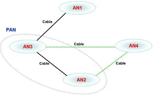
The reference scenario for the HT implementation is shown in Figure 17. Any ‘oval’ represents a generic AN, which could be an operator server, an infrastructure relay node, a user terminal and even more, as the AN approach is designed to be applicable to any network configuration. Each line represents a link of a specified technology and the technology is indicated close to the line. The black lines represent the initial route for services provided by AN1 to AN2. The green dotted lines represent a new possible better route (e.g. cheaper or providing bigger bit-rate) for these services. AN2 and AN3 are in the same Personal Area Network (PAN).
Note that the Ambient Network project aims to integrate any technology in any possible situation, so this first reference scenario could be complicated as you like in future and gradually other options will be added in some messages in order to obtain an integration of all technologies. For example, link between AN1 and AN3 could become 2G/3G, that one between AN2 and AN4 WLAN, and link between AN3 and AN2 Bluetooth (BT). However, the main thing is to demonstrate feasibility and advantages provided by using HT, for example reducing packet loss, handover latency, costs and also providing a number of better opportunities, both for users and service providers, given that each network (that is an AN) becomes more aware of surrounding context and can share its available resources in order to offer and to obtain more services and more benefits.
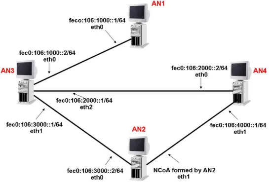
In Figure 18 is shown the configuration of PCs used for testing in SMC’s (Siemens Mobile Communications) laboratory.
4.2. Messaging timeline and handover storyline
The following steps and actions describe the exchange of messages implemented in order to create the handover scenario, but there are also indicated by the term “could” possible actions, already provided or imminent, for further useful scenarios. Note that between square brackets are indicated the Ambient Networks Options involved in that packet.
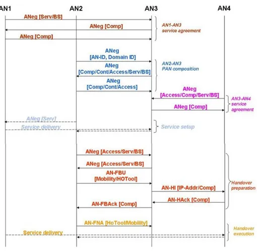
The messaging timeline is shown in Figure 19, where in the square brackets are shown the options carried by each packet. Format and meaning of each message is illustrated in section 4.3.
First step: “Service Agreement” between AN1 and AN3
An ANeg [Serv/BS Opts] message is sent from AN1 to AN3: AN1 advertises itself to AN3, indicating its provision of services (Serv) and bearer services (BSs). It was assumed AN1 has a leading role in controlling resources on the link AN1-AN3. Values of main fields are:
- Service Option: Option Code = 2, that is “I offer”.
- Bearer Service Option: Option Code = 1, that is “I have”.
An ANeg [Comp Opt: Option Code = 1], that is composition request message, is sent from AN3 to AN1: AN3 registers to AN1, indicating its willingness to compose to it.
Figure 19: Messaging timeline
An ANeg [Comp Opt: Option Code = 3], that is Composition agreed message, is sent from AN1 to AN3: AN1 acknowledges AN3 request for composition.
AN1 services are now available to AN3.
Second step: “PAN Composition” between AN2 and AN3
AN2 advertises its identity and domain through an ANeg message sent on its eth0 card. AN3 is also active on the same link, therefore it responds with ANeg including a request to compose, some context information (e.g., the user is not at AN3) and a description of its access routes. AN2 responds
agreeing composition, replying also with some context information (e.g., user is at AN2) and information regarding access routes.
An ANeg [AN-ID, Domain-ID] message is sent from AN2 to AN3: AN2 advertises itself to AN3, indicating its identity and domain.
An ANeg [Comp/Cont/Access/Serv/BS Opts] message is sent from AN3 to AN2. AN3 indicates to AN2 info both regarding AN3 and AN1, and its willingness to compose in a PAN. Furthermore, AN3 communicates to AN2 that it can act as an access router for AN2 itself, forwarding to it incoming packets destined to AN2’s interfaces: in fact, AN3 uses the Access Route Option to indicate that it is the Route End and hence the Access AN (flag M = 0) for AN2. Values of main fields are:
- Composition Option: Option Code = 1, that is composition request. - Context Option: ContextInfo = 2, that is “User is not here”.
- Access Route Option: Method = 5, that is cable; Route Head = AN1; Route End = AN3; Flag M = 0, that is specifying the access AN (AN3); Option Code = 2, that is “I offer”.
- Service Option: Option Code = 2, that is “I offer”.
- Bearer Service Option: Option Code = 1, that is “I have”.
An ANeg [Comp/Cont/Access Opts] message is sent from AN2 to AN3: AN2 acknowledges AN3 request for composition and advertises user info (user is working on AN2) and its other type of access (AN2’s eth1 card) to AN3. Values of main fields are:
- Composition Option: Option Code = 3, that is Composition agreed. - Context Option: ContextInfo = 1, that is “User is here”.
- Access Route Option: Method = 5, that is cable.
Third step: “Service Agreement” between AN4 and AN3
AN4 advertises any AN on its links, indicating that it offers an access route by sharing its Ethernet cards, indicating also the BSs available on it and the willingness to compose with an other AN to provide such bearer services. AN3 responds accepting the composition.
An ANeg [Access/Comp/Serv/BS Opts] message is sent from AN4 to AN3: AN4 advertises itself to AN3, indicating what is offering and its willingness to compose (e.g. there exist previous agreements between the two ANs). Values of main fields are:
- Access Route Option: Method = 5, that is cable. - Service Option: Option Code = 2, that is “I offer”.
- Bearer Service Option: Option Code = 3, that is “I offer”.
- Composition Option: Option Code = 1, that is composition request. An ANeg [Comp Opt: Option Code = 3], that is Composition agreed message, is sent from AN3 to AN4: AN3 acknowledges AN4 request for composition.
Fourth step: “Service Setup”
Service transmission is started between AN1 and AN2.
An ANeg [Serv Opt] message is sent from AN2 to request one or more services to AN1 (via AN3). In this scenario there are a streaming request and a download request. In case that AN2 does not receive the service(s) required to AN1 by a certain amount of time (service_time_retrieval), AN2 must retry to send the same ANeg message to AN1 for a maximum number of 3 times. If after 3 attempts the service required does not start, AN2 must admit that there is some problem for AN1 and that service(s) could not delivered.
The ANeg [Serv Opt] message contains two Service Options, one for streaming service and the other for download service request. Values of main fields are:
First Service Option:
- Option-Code = 1, that is “I require”. - Service = 2, that is streaming.
- IP-Address = AN2’s IPv6 address for streaming service. Second Service Option:
- Option-Code = 1, that is “I require”. - Service = 3, that is download.
- IP-Address = AN2’s IPv6 address for download service.
Note that this is a particular case of multi-homing: for each session active on AN2 is assigned a particular IPv6 address, separating so mobility management from sessions management. In this way, if there are some sessions active at same moment on the same access technology and if there is the need or the opportunity to handoff only a subset of those sessions, this can be done easily. In traditional usage of access technologies, there is the same IPv6 address shared for all sessions active at that time.
AN1 accepts both AN2’s requests and it starts transmitting the services. From now on, AN3 forwards to AN2 the incoming packets destined to AN2’s interfaces.
Fifth step: “Handover preparation”
In this one and in the next step the HT commands used by each AN are underlined.
Discover new accesses and routes; Info Exchange:
Immediately after starting the services in order to secure stability of the transmission, or due to some lower layer reasons (some ARI triggers), AN2 believes or detects that the AN3-AN2 link may not suffice, therefore it solicits AN3 to notify about any modification or new options on the access routes between AN1 and AN2. AN3 answers indicating the possible alternative access route AN1-AN3-AN4 with cable access method.
An ANeg [Access/Serv/BS Opts] message is sent from AN2 to AN3: AN2 instructs AN3 to keep looking for better opportunities, for this reason it uses a wildcard [1] (in order to obtain info about all neighbours and possible access routes). But there could be also the possibility that AN2 discovers a number of APs and asks related information to AN3, in order to find a valid alternative route. Values of main fields are:
- Access Route Option: Method = 5, that is cable.
- Service Option: Option Code = 1, that is “I require”; Service = 2, that is streaming.
- Bearer Service Option: Option Code = 2, that is “I require”.
In other words, AN2 is asking (“I require”) to AN3 to find a better route for streaming service (Service = 2) exploiting its eth1 card with cable (= Method) access.
An ANeg [Access/Serv/BS Opts] message is sent from AN3 to AN2: AN3 recognises a possible better opportunity for AN2 (lower cost and/or better link quality/higher bit-rate), and advertises route AN3-AN4-AN2 (green dotted lines in Figure 17) to AN2, indicating info, which could be a valid IPv6 address for AN2 to use in the new subnet at AN4, or the prefix part of the new link (such as in this scenario) in order to form a new valid IPv6
address for the new subnet. Further info indicated in this message is the bearer service offered for that service required. Values of main fields are: - Access Route Option: Method = 5, that is cable; Route Head = AN1; Route End = AN4; Flag M = 0, that is AN4 is the Access AN.
- Service Option: Option Code = 2, that is “I offer”; Service = 2, that is streaming.
- Bearer Service Option: Option Code = 3, that is “I offer”. There is also specified bit-rate offered in the field Bit-Rate-Value.
In other words, AN3 is offering to AN2 an alternative route for streaming service (Service = 2) characterized by a certain bit-rate value specified in the Bearer Service Option. The route head is AN1 and the route end is AN4 that is also the Access AN (flag M = 0).
Authentication/Authorisation/Registration (A/A/R):
AN2 based on some triggers from ARI, or based on handover history or other, decides it is better to prepare handover towards the potentially alternative route. AN2 therefore issues an AN-FBU [Mobility/HoTool/Comp Opts] with the just formed address (in order to validate it) and asks AN3 to start a preventive A/A/R at AN4 (inserting in this message its MAC address), requiring also a composition with AN4. Besides, AN2 puts a Handover Toolbox Option in the AN-FBU message, selecting the appropriate HO Command to continue sending all packets on the old link, until a AN-FNA is not received by AN3. Values of main fields are:
- Mobility Option: IPv6 address just formed (to validate).
- HO Toolbox Option: HO Command = 1, that is “Continue sending on the old link”, until a AN-FNA is not received.
More in general, the AN-FBU could include an option indicating whether to continue sending packets on the old link until the AN-FNA is received, or to start forwarding packets to the NAR (AN4) which could buffer these, or to start bicasting.
Resource Reservation; Forward; Start Buffering:
During the AN-HI [IPAddr/Comp Opts]/AN-Hack [Comp Opt] exchange of messages between AN3 and AN4, AN3 makes A/A/R for AN2 at AN4 and it validates the just formed IPv6 address to use by AN2 on new link (AN2-AN4). More in general, AN3 could also request AN4 to reserve resources in order to buffer incoming packets destined to AN2’s interfaces, or to start buffering from now, until a FNA message is received at AN4. The AN-HAck message contains all answers for all requests involved in the AN-HI message, such as the possibility or less to reserve resources for buffering, or a valid alternative IPv6 address for AN2’s interfaces if the just formed IPv6 address was not valid or already in use on the new link. In this scenario is assumed that the IPv6 address formed by AN2 is valid. Values of main fields for AN-HI [IPAddr/Comp Opts] message are:
- IP Address Option: it includes the IPv6 address formed by AN2 (to validate).
- Composition Option: Option Code = 1, that is composition request for AN2 at AN4.
Values of main fields for AN-HAck [Comp Opt] message are:
- Composition Option: Option Code = 3, that is composition agreed. AN4 accepts AN2’s composition request communicated by AN3’s AN-HI message.
In this case there is not an alternative IPv6 address in the AN-HAck message, because the address formed by AN2 is valid. Otherwise, AN4 must insert a valid alternative IPv6 address for AN2’s eth1 card.
An AN-FBAck [Comp Opt] message is sent from AN3 to AN2: AN3 confirms AN2 the successful (in this scenario) or unsuccessful (in other cases) operations and it validates the IPv6 address previously formed by AN2 (if this address is not valid or already in use, then the message contains a valid alternative IPv6 address). Values of main fields for AN-FBAck message are:
- Composition Option: Option Code = 3, that is composition agreed. AN3 communicates to AN2 that composition has tooken place.
Sixth step: “Handover Execution”
After some triggers, AN2 decides to handover the download service on the new route by sending an AN-FNA to AN3.
Change active routes; Session flows reconfiguration; Forward:
The AN-FNA [HOTool/Mobility Opts] message is a handover command sent from AN2 to AN3. Value of main fields are:
- HO Toolbox Option: HO Command = 2, that is “Forward on the new link and stop sending on the old link”.
- Mobility Option: IPv6 address used on the old link for service that is in process to handover towards the new link and to the new address.
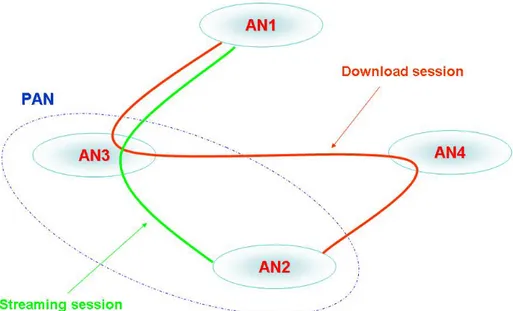
Figure 20: Post-HO configuration of the active sessions
In other words, when AN3 receives the AN-FNA message, it understands from which address must handover a session and which is the session to handoff. In fact, there is a univocal relation (1:1) between type of session and IPv6 address assigned to the interface used for that session. See Figure 20 for post handover configuration of the active sessions.
4.3. ANeg messages format and meaning
In this section are illustrated ANeg messages format and meaning, but are not presented format and meaning of AN-FBU, AN-HI, AN-HAck, AN-FBAck and AN-FNA messages, because their format is the same proposed in [1] with
some ANeg Options stuck, while their meaning is shown in section 4.2. Each ANeg message (as well as the other AN messages) was created ex-novo by using tools explained in section 4.4. An ANeg is an ICMPv6 packet: see [2] for ICMPv6 message format and meaning.
4.3.1. ANeg ICMPv6 message format
An ANeg message may contain advertisements and/or requests for the couples AN ID/Domain ID carried. If it is an advertisement message, then each couple is publicized to other ANs, in order to inform and give more awareness of surrounding environment to neighbours. Otherwise, each couple represents an info request for receiver. An AN could belong to one or more AN Domains and having one or more AN IDs.
At the moment, the value of Type field is not defined and there are used temporary values.
The same Negotiation ID is used between the negotiating parties for referring to the same thread of messages.
0 1 2 3 0 1 2 3 4 5 6 7 8 9 0 1 2 3 4 5 6 7 8 9 0 1 2 3 4 5 6 7 8 9 0 1 +-+-+-+-+-+-+-+-+-+-+-+-+-+-+-+-+-+-+-+-+-+-+-+-+-+-+-+-+-+-+-+-+ | Type | Code | Checksum | +-+-+-+-+-+-+-+-+-+-+-+-+-+-+-+-+-+-+-+-+-+-+-+-+-+-+-+-+-+-+-+-+ | Subtype | Length | Negotiation ID | +-+-+-+-+-+-+-+-+-+-+-+-+-+-+-+-+-+-+-+-+-+-+-+-+-+-+-+-+-+-+-+-+ | AN ID | + + | | + + | | + + | | +-+-+-+-+-+-+-+-+-+-+-+-+-+-+-+-+-+-+-+-+-+-+-+-+-+-+-+-+-+-+-+-+ | AN Domain | + + | | + + | | + + | | +-+-+-+-+-+-+-+-+-+-+-+-+-+-+-+-+-+-+-+-+-+-+-+-+-+-+-+-+-+-+-+-+ | AN ID | + + | | + + | | + + | | +-+-+-+-+-+-+-+-+-+-+-+-+-+-+-+-+-+-+-+-+-+-+-+-+-+-+-+-+-+-+-+-+ | Options ... +-+-+-+-+-+-+-+-+-+-+-+-
Type AN Info type: To be defined
Checksum The ICMPv6 checksum
Subtype 1 (ANeg: Negotiation)
Length The size of this message in 8 octets unit, including the subtype and length fields.
Negotiation ID MUST be set by the sender so replies can be matched to this message
AN ID 128 bit AN identifier
AN Domain 128 bit AN Domain identifier
4.3.2. ANeg Options
It follows a list of possible options that could be present in an ANeg message. All options presented are in TLV format. Note that the order in which these are proposed, it is not necessary the same in which these must be included in a message: each option can be easily recognised by means of Type field. Only the Bearer Service Option (one or more) must follow the Service Option, if the latter is present.
4.3.2.1. Composition Option
Composition Option allows ANs to compose either. In the composition request message, field AN/Domain ID contains a receiver’s AN ID, if sender wants to compose with all receiver’s domains. Otherwise sender specifies which receiver’s Domain ID(s) it wants to compose with. If there are more
Domain ID which to compose with, then sender will insert a Composition Option for each one.
At the moment, the value of Type field is not defined and it is used a temporary value for ANeg Composition Option.
+-+-+-+-+-+-+-+-+-+-+-+-+-+-+-+-+-+-+-+-+-+-+-+-+-+-+-+-+-+-+-+-+ | Type | Length | Option-Code | Reserved | +-+-+-+-+-+-+-+-+-+-+-+-+-+-+-+-+-+-+-+-+-+-+-+-+-+-+-+-+-+-+-+-+ | AN/Domain ID | + + | | + + | | + + | | +-+-+-+-+-+-+-+-+-+-+-+-+-+-+-+-+-+-+-+-+-+-+-+-+-+-+-+-+-+-+-+-+
Type Option Type: to be assigned
Length The size of this option in 8 octets including the Type, Length and Option-Code fields
Option-Code 1 - Composition Required with the indicated AN/Domain
2 - Decomposition Required with the indicated AN/Domain
3 - Composition Agreed 4 - Composition Not Agreed
4.3.2.2. HO Toolbox Option
HO Toolbox Option represents the commands to use in order to construct any type of handover in any situation. The HO Command field is a list of possible handover commands provided by implementation. Note that it is possible to request a resources reservation in terms of buffer length value, as specified by fields BuffValue and BuffExp. The HO ID fields allows to distinguish between possible various HO Command requests coming from different ANs.
At the moment, the value of Type field is not defined and it is used a temporary value for ANeg Ho Toolbox Option.
+-+-+-+-+-+-+-+-+-+-+-+-+-+-+-+-+-+-+-+-+-+-+-+-+-+-+-+-+-+-+-+-+ | Type | Length | Option-Code | Reserved | +-+-+-+-+-+-+-+-+-+-+-+-+-+-+-+-+-+-+-+-+-+-+-+-+-+-+-+-+-+-+-+-+ | BuffValue | BuffExp | HO ID | HO Command | +-+-+-+-+-+-+-+-+-+-+-+-+-+-+-+-+-+-+-+-+-+-+-+-+-+-+-+-+-+-+-+-+
Type Option Type: to be assigned
Length The size of this option in 8 octets including the Type, Length and Option-Code fields
Option-Code 1 - Require 2 - Offer
BuffValue 8-bit unsigned integer
BuffExp 8 bit unsigned Exponent,
Buffer Length= BuffValue * 10 ^ BuffExp
HO ID HO Identifier
2 - Forward new access and stop sending on the old link
3 - Bicasting
4 - Buffer and continue sending on the old link 5 - Buffer and forward new access and stop sending on the old link
6 - Buffer and bicasting
7 - Send buffered data on the old link 8 - Send buffered data on the new link 9 - Send buffered data in bicasting 10 - Flush Buffered Data
4.3.2.3. Service Option
Service Option is designed to advertise or to request other ANs the services that sender of message places at other AN’s disposal or it is requiring, respectively. One or more Bearer Service Option must follow a single Service Option: field Length indicates how many Bearer Service Option are. At the moment, the value of Type field is not defined and it is used a temporary value for ANeg Service Option. Value of Service field also is not defined: at the moment there are used temporary value of 1 for HTTP, 2 for Streaming, 3 for Download service.
+-+-+-+-+-+-+-+-+-+-+-+-+-+-+-+-+-+-+-+-+-+-+-+-+-+-+-+-+-+-+-+-+ | Type | Length | Option-Code | Service | +-+-+-+-+-+-+-+-+-+-+-+-+-+-+-+-+-+-+-+-+-+-+-+-+-+-+-+-+-+-+-+-+
Type Option Type: to be assigned
Length The size of this option and the following Bearer Service Option(s) in 8 octets including the Type, Length and Option-Code fields
Option-Code 1 - Require 2 - Offer
Service To be defined.
4.3.2.4. Context Option
Context Option allows to inform any AN about user location, for now.
At the moment, the value of Type field is not defined and it is used a temporary value for ANeg Context Option.
+-+-+-+-+-+-+-+-+-+-+-+-+-+-+-+-+-+-+-+-+-+-+-+-+-+-+-+-+-+-+-+-+ | Type | Length | Reserved | Context Info | +-+-+-+-+-+-+-+-+-+-+-+-+-+-+-+-+-+-+-+-+-+-+-+-+-+-+-+-+-+-+-+-+
Type Option Type: to be assigned
Length The size of this option in 8 octets including the Type, Length and Reserved fields
ContextInfo 1 - User is here 2 - User is not here 3 - Where is the user?
4.3.2.5. Access Route Option
At the moment, the value of Type field is not defined and it is used a temporary value for ANeg Access Route Option. Value of (Access) Method field also is not defined: there are used temporary value of 1 for GSM, 2 for UMTS, 3 for WLAN, 4 for BT, 5 for Cable.
Route Head is an optional field. The flag M (or the field Length) indicates if it is present or less: if flag M is set to 1, then it specifies that Route End field indicates the domain that is accessed through it, and the Route Head field is not present; if flag M is set to 0, then it specifies both Route Head and Route End, indicating also that Route End is the access AN.
+-+-+-+-+-+-+-+-+-+-+-+-+-+-+-+-+-+-+-+-+-+-+-+-+-+-+-+-+-+-+-+-+ | Type | Length | Option-Code | AR Number | +-+-+-+-+-+-+-+-+-+-+-+-+-+-+-+-+-+-+-+-+-+-+-+-+-+-+-+-+-+-+-+-+ | Method |M| Reserved | Reserved | +-+-+-+-+-+-+-+-+-+-+-+-+-+-+-+-+-+-+-+-+-+-+-+-+-+-+-+-+-+-+-+-+ | Route Head (optional) | + + | | + + | | + + | | +-+-+-+-+-+-+-+-+-+-+-+-+-+-+-+-+-+-+-+-+-+-+-+-+-+-+-+-+-+-+-+-+ | Route End | + + | | + + | | + + | | +-+-+-+-+-+-+-+-+-+-+-+-+-+-+-+-+-+-+-+-+-+-+-+-+-+-+-+-+-+-+-+-+
Type Option Type: to be assigned
Length The size of this option in 8 octets including the Type, Length and Option-Code fields
Option-Code 1 - I have 2 - I offer
3 - I may require 4 - I request
AR Number Access Route number
(Access) Method: To be defined.
M 0 - Route end
1 - Access AN
4.3.2.6. Bearer Service Option
One or more Bearer Service Options must follow a single Service Option: it could be considered as a “sub-option” of the latter, because each one specifies a particular characteristic for the service indicated by the Service field. For example, an Ambient Network could request for a service a certain bit-rate value in downlink, and another value in uplink: these are two Bearer Service Options for the same Service Option.
At the moment, the value of Type field is not defined and it is used a temporary value for ANeg Bearer Service Option.
Option Code field specifies the meaning of option; Link Reference, BitRateValue and BitRateExp fields indicate what is available or required for that service.
+-+-+-+-+-+-+-+-+-+-+-+-+-+-+-+-+-+-+-+-+-+-+-+-+-+-+-+-+-+-+-+-+ | Type | Length | Option-Code | Service | +-+-+-+-+-+-+-+-+-+-+-+-+-+-+-+-+-+-+-+-+-+-+-+-+-+-+-+-+-+-+-+-+ | Link Reference | BitRateValue | BitRateExp | +-+-+-+-+-+-+-+-+-+-+-+-+-+-+-+-+-+-+-+-+-+-+-+-+-+-+-+-+-+-+-+-+
Length The size of this option in 8 octets including the Type, Length and Option-Code fields
Option-Code 1 - I have 2 - I require 3 - I offer
Link Reference 1 - Uplink 2 - Downlink
3 - Uplink and downlink separately 4 - Uplink and downlink together
BitRateValue 8-bit unsigned integer
BitRateExp 8 bit unsigned Exponent,
BitRate= BitRateValue * 10 ^ BitRateExp
4.4. Implementation basics
The implementation is based on Ambient Network exchange of messages. The messages are created by using IPv6 Raw Sockets, which bypass the transport layer (TCP or UDP), which could be used for ICMPv6 messages and to read and to write IPv6 datagrams containing a Next Header field, that the kernel does not process (examples of the latter are a routing daemon for OSPF [3] for IPv6 and RSVP [4] – protocol field 46). Raw Sockets provide a way to manipulate sockets directly at the IP layer, something which is not possible through the standard sockets API, since that provides access to the layer above IP, i.e. TCP or UDP. Raw Sockets are often used to implement functionality that the standard sockets API cannot provide, such as sending IP datagrams carrying payload for protocols other than TCP or UDP, or which need to be dealt with by the application instead of by the kernel. A Raw Socket is simply a rough socket created to send and receive data from a
PC to one or more PCs, where data could be created by user. The choice to use IPv6 instead of IPv4 should be very clear, given that IPv6 represents the future standard for network layer. In past, several programs and applications were created by using IPv4 Raw Sockets: so, it is easy to foresee that as many will be created by using IPv6 Raw Sockets. But IPv6 Raw Sockets differ from IPv4 Raw Sockets in some points, as you can see in [5]. Probably, the main difference is that all data sent via an IPv6 Raw Socket must be in network byte order (which is big-endian for the Internet protocols) and all data received via raw sockets will be in network byte order. In IPv4 Raw Sockets, instead, there is not the necessity to use a byte ordering, so is used a host’s byte order for a certain header field. An other difference from IPv4 Raw Socket is that complete packets, that is, IPv6 packets with extension headers (Routing header, Hop-by-Hop options and Destination options), cannot be sent or received using the IPv6 Raw Sockets API. Two different mechanisms exist for sending this optional information:
- “ancillary data” objects, which are used to transfer the extension headers and hop limit information. The ancillary data fields were added to the 4.3BSD Reno sockets API in 1990 and are part of the Posix standard [6], therefore these should be adopted by most vendors. Ancillary data specify the option content for a single datagram, but this only applies to datagram and Raw Sockets, not to TCP sockets.
- setsockopt(): is used to specify the option content for a socket. The options are stuck to all transmitted packets (for this reason these are often called as “sticky” options) on the socket until either a new setsockopt is done or the options are overridden using ancillary data.
We chose to use the setsockopt mechanism, because sticky options are supported for TCP.
Ambient Network messages have been created and are sent by using Raw Sockets, but each machine must also capture and recognize these, and that is
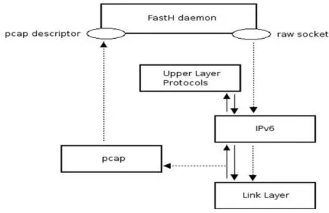
possible thanks to libpcap library. “pcap” is a system-independent interface for user-level packet capture: it provides a portable framework for low-level network monitoring. Applications include network statistics collection, security monitoring, network debugging, etc. The packet-filtering engine is actually implemented inside the pcap library which is an OS-independent wrapper for the BPF (Berkley Packet Filter) engine. One of the most useful functions provided by libpcap is pcap_compile(), which takes a string containing a logic expression as input an outputs the BPF filter code. If an incoming packet matches filter’s rules, the packet is accepted by the filter and it is passed to daemons. In such way, modules receives copies of packets that passed filtering rules and can analyze format and content of each byte forming that packet.
Figure 21 is auto-explicative and shows how raw sockets and pcap work together, where FastH daemon is the implementation code of HO Toolbox. IPv6 Raw Sockets and libpcap are used on Linux Red Hat distribution, in which the IPv6 stack is already available. Definitions of the basic constants and structures required for applications to use IPv6 Raw Sockets, some basic semantic definitions for IPv6 Raw Sockets and packet information(i.e. how applications can obtain the received interface, destination address, etc.), are illustrated in the [5].
Figure 21: Work performed by raw sockets and libpcap
It’s important to note that implementation is kernel release independent. This choice was dictated by several reasons:
1. To release oneself from a particular kernel release, avoiding to update implementation for each new kernel release, until the project will not be arrived to the goal.
2. To easily work in user space rather than in kernel space.
3. To easier translate the code from a Linux distribution to different distributions (e.g. easily changing the libraries included in code). Obviously performances of the machines are quite worse than a kernel implementation, but in this phase of project (that is the first) does not make so sense to bind oneself to a particular kernel release. When each working group of the Ambient Network project will complete its work and these single works will be harmonized, then will make greater sense to develop a kernel implementation.
4.5. Mapping between Fast Handovers for Mobile
IPv6 and HT implementation
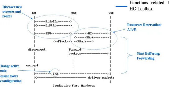
Figure 22: Mapping between Fast HO and HT implementation
A Handover Engine uses the HO Toolbox commands to build the appropriate HO process based on received triggers and on the reference scenario. The HO toolbox may be used to realize the case of “Predictive Fast HO” provided as proposed in the [1]. The mapping between HO Toolbox commands of implementation and the case of “Predictive Fast HO” is shown in Figure 22. Note that each ANeg message even if corresponds to a particular message described in IETF draft, truly assumes a wider meaning as you can see in section 4.2.
Referring to HO storyline, AN2 corresponds to MN of IETF draft. MN could perform “Discover new accesses & routes” command before sending RtSolPr, or through RtSolPr it could ask the PAR, corresponding to AN3, to perform this command providing feedback in PrRtAdv (e.g.: wildcard [1]). The RtSolPr corresponds to ANeg [Access/Serv/BS] sent from AN2 to AN3,
in which AN2 asks AN3 to find a better route (wildcard) or to give info about new APs discovered by AN2 itself. The PrRtAdv corresponds to ANeg [Access/Serv/BS] sent from AN3 to AN2.
AN-FBU, AN-HI, AN-HAck and AN-FBAck messages correspond respectively to FBU, HI, HAck and FBAck messages of IETF draft. The NAR corresponds to AN4 and the CN to AN1. AN3 performs an “A/A/R” for AN2 at AN4 to validate the IPv6 address just formed by AN2: this is the same sequence of operations proposed by IETF draft. Besides, in the AN-HI message, AN3 could request to reserve resources using the “Reserve
Resources” command for buffering packets destined to AN2: this is the
same behaviour proposed by IETF draft in the description of HI message. When AN4 send the AN-HAck message to AN3, AN4 starts buffering using the “Start buffering” command. As soon as AN3 receives the AN-HAck message, it starts forwarding to AN4 the incoming packets destined to AN2, in order to prevent packet loss: this is possible using the “Forwarding” command.
Handover command “Change active route” is contained in the AN-FNA message, that corresponds to FNA, according to its meaning. This command is also a particular case of the “Session flows reconfiguration” command, given that in this case there is a reconfiguration (handover) of all sessions active in that moment. Differently from reference scenario for the HO Toolbox implementation, the AN-FNA message is sent from AN2 to AN4 and not to AN3: in fact, in this case it is a command to deliver buffered data.