Chapter 4 Developed Handling devices for microproducts
Chapter 4
Developed
Handling devices for microproducts
4.1 Introduction
In the PhD research activities, different handling devices have been designed, realized and tested. In this Chapter, the developed handling devices are described and the experimental results reported. These systems are an electrostatic positioning device (please refer to § 4.2.1), an electrostatic sorter (please refer to § 4.2.2), some mechanical grippers (please refer to § 4.2.3), and an electromagnetic micropositioner (please refer to § 4.2.4).
Chapter 5 will show how these systems are integrated in the prototype of microfactory in progress at the Department of Mechanical, Nuclear and Production Engineering (DIMNP) of the University of Pisa.
4.2 Handling devices developed in the research
4.2.1
The electrostatic centering device
[1]Aim of the device
The two topics the centering devices want to face in the handling of microcomponents are:
• no control of the final position of the part to be handled • avoid sticking effects in releasing microparts
Actually, one of the main problems of several electrostatic feeders is the limited or complex control of the final position of handled parts. So, these parts have to be localized by vision systems or other sensors before being grasped. On the contrary, the assembly microfactory concept needs feeding systems that move components to a set pick-up position [2]. Furthermore, when grasped by a gripper, the releasing of little parts is very difficult as shown in § 3.2.2. If parts are conveyed by a non contact strategy, the benefit is that the problem of sticking in releasing is avoided.
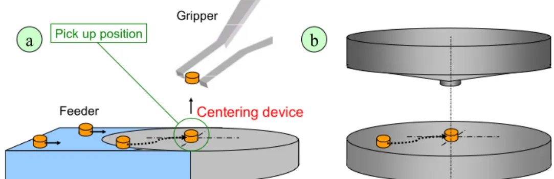
Hence, a centering device for handling microparts represents both an interface between the feeding and the grasping task (Figure 1a) and a simple micro positioning device (Figure 1b): the parts conveyed randomly by a feeder system or randomly placed in the workspace of the centering device are shifted to a fixed position. Once centered, microparts are ready to be grasped with a gripper that always moves in the preset position.
Microhandling devices for the assembly of Hybrid Microproducts
Feeder Centering device
Gripper
Pick up position
a
b
Figure 1: Aim of the electrostatic centering device.
The experimental device and the control parameters
Various strategies can be used to center microobjects [3]. It is well known that both conductive and dielectric materials are attracted towards regions with higher electric field (or equivalent with potential minima) [2]. The developed centering device makes use of an electrostatic field with a radial gradient and a maximum in the center to move objects into the desired position. If electrostatic forces overtake adhesion and friction ones, microparts will be shifted towards the center as explained in the following.
The experimental prototype developed to validate this centering strategy is shown in Figure 2: it consists of a special capacitor with a conic (1) and a round plane electrode (2), a high voltage supply (3), a wave generator (4) and a piezoelectric disc (5).
D
+
-3
4
V φ d1 d2 d1 d3 d25
A,υ 1/υ A2
1
P
C
d h 1a 2aChapter 4 Developed Handling devices for microproducts
The capacitor, supplied with high voltage, permits to obtain a radial electrostatic field with the maximum in the center. The vibration of the platform, obtained by means of the piezoelectric disk supplied with the wave generator, allows a high reduction of friction and a partial reduction of adhesion between objects and the platform. Actually, as reported in literature [2][4][5] (and checked by preliminary tests), the reduction of surface forces is required to allow electrostatic forces overtake friction and adhesion in transporting parts with dimensions of few hundreds microns and mass of few milligrams. This reduction is particular important when humidity is more than 8% [6][7].
As FEM analysis has demonstrated, while simple conic electrode has a point of maximum, a protuberance on the top of the cone causes the electrostatic field to extend the maximum value to a zone around the axis, being the shape of the zone a function of the protuberance. Because the protuberance should improve the centering stability of microobjects, a cylindrical (C) or a prismatic (P) protuberance (Figure 2, particular 1a) have been tested: the shape of the protuberance depends on the object to be centered. In addition, preliminary tests revealed a shift of the microobjects after the electrostatic field had been deactivated. This shift, that affects especially dielectric components, is probably caused by the polarization of the microobject that persists during the capacitor discharge making the object attracted towards zones of opposite charge. In order to reduce this shift, in the centering tests on spheres the plane electrode was provided with a conic hole (d=1mm ; h=0.1mm) in the geometrical center (Figure 2, particular 2a). On the contrary, tests on cylinders have used a plane platform.
As shown in Table 1, the electrostatic field depends on: the applied voltage (V), the distance between electrodes (D), the angle of the cone (φ) and the geometrical dimensions (d1 ; d2 ; d3) of the upper electrode protuberance, while the vibration of the
platform is characterized by its amplitude (A) and frequency (υ). The vertical distance between the upper and the lower electrode (D) can be controlled by a micrometer lead screw. The angle of the cone (φ) and the geometrical dimension of the protuberance (d1, d2 for the cylinder; d1, d2, d3 for the prism) are modified by the substitution of the
upper electrode. The voltage (V), the frequency (υ), and amplitude (A) of the vibration can be directly set by modifying the outputs of the high voltage supply and of the wave generator. A tester has been used to control the applied voltage, while the real amplitude and frequency of the vibration platform has been measured by means of a laser interferometer specially realized.
0.6µm 1.5-18µm A vibration amplitude 1 Hz 2000Hz (constant) υ vibration frequency Vibrat io n Vibra tio n 10µm d1=0.5-1.5mm d2=0-1mm d3=0.2-0.7mm d1 d2 d3 protuberance dimension 0,1° 6-10° φ
angle of the conic electrode
10 V 0.5-2kV V voltage 10µm 1.5-3mm D distance E le ctr os ta tic fi eld s Elec tro sta tic field s Error Range Symbol Parameters
Microhandling devices for the assembly of Hybrid Microproducts
The theoretical analysis
a) Force analysis
The forces acting on a component [8][9] are:
1. electrostatic force (generated by the electrostatic field) 2. adhesive forces
3. gravity (and inertia when the component moves) 4. friction
These forces, in the case of the centering electrostatic device, are qualitative shown in Figure 3:
-E
G
F
R
+
-+
+
-E: electrostatic force (external field) G: gravity force
A: adhesion forces F: friction
R: reaction
I: electrostatic force due to image charges
A
I
I
E
rE
z r z θ Conductive platformFigure 3: Forces acting on the components.
With regard to the electrostatic force generated by the electric field, it can be split in terms of axial and radial components: Ez contributes to detach the object from the platform, while Er acts toward the center of the device (i.e. towards the positive gradient of the electrostatic field). The adhesive force (surface tension, van der Waals, electrostatic) makes the object adhere to the platform and becomes important, as shown in § 2.1.1, when the dimension of the object is less than 1 mm. In particular, the external electric field induces charges in the object that, as the image theorem predicts, are attracted towards their “charge images” virtually positioned under the conducting platform.
Other forces are gravity that is directed, as obvious, downward and inertia when the component moves. Finally, there is the friction force that acts parallel to the platform with opposite versus to the motion of the object.
In conclusion: the object is able to move toward the center if the electrostatic force overtakes friction and adhesion ones. The vibration is used to detach the object from the platform and consequently to reduce adhesion forces and friction. Actually, the object tilts on the platform decreasing its contact surface and augmenting its distance from the base. b) Electrostatic field analysis
Even if the presence of the component between the two electrodes alters the electrostatic field, as a first approximation the force on components can be considered proportional to the unmodified electric field [4][10]. With this assumption, numerical and FEM analyses of
Chapter 4 Developed Handling devices for microproducts
the radial electrostatic field have been performed. The two analyses both show the presence of a radial electrostatic field increasing from the periphery toward the center. In Figure 4, it is shown the analysis in case of a simple conic electrode with an angle of 164°, a radius of the electrodes of 10 mm, a distance between electrodes of 1.5 mm. The numerical analysis points out the radial electrostatic field with a charge of 2.6·10-10 C on the electrodes at 0.6 mm from the platform while the FEM analysis shows the radial electrostatic field within the electrodes with a potential difference of 1000 V.
R 0 1 2 3 4 5 6 7 8 9 10 (mm) Er (N/C) 1 ·104 2 ·104 3 ·104 4 ·104 5 ·104 6 ·104 FEM Analysis Numerical Analysis
(Erwithin electrodes with a DP of 1 kV)
R Er φ d r H -Conic electrode (φ): 164° -Radius of electrode (r): 10 mm -Electrodes distance (d): 1.5 mm
(Er with a charge of 2.6·10-1O C at H=0.6)
Figure 4: Theoretical analysis of the radial electrostatic field between electrodes.
Tested microobjects and centering performance
The tested microobjects were microspheres and microcylinders: their features are shown in Figure 5. These microobjects are typical parts manipulated in microassembly tasks [11]. 14.3 d=0.5; b=1.5 steel cylinder 2 2.7 d=1.5; h=1.5 steel cylinder 1 2.9 d=0.8 steel sphere 3 6.9 d=1.2 steel sphere 2 2.4 d=1.2 glass sphere 1 Mass (mg) Dimension (mm) Material Object 1 2 3 4 5 1 2 3 4 5
Figure 5: Tested microobjects.
The aim of the tests was the identification, by the selection of suitable control parameters, of the electrostatic field and the platform vibration able to give an acceptable and efficient centering of microobjects.
Acceptable centering was evaluated by considering the centering precision (i.e: the distance between the centre of mass of the object and the axis of the upper electrode) and centering stability (i.e.: the object shifts from the center after the electrostatic field has
Microhandling devices for the assembly of Hybrid Microproducts
been deactivated). The centering stability is very important because once the micropart is centered, the electrostatic field has to be deactivated to let a microgripper (different from an electrostatic one) grasp the object (please refer to the following § “Integration with grippers”). With respect to cylinders, it is also important to appraise the centering orientation. Hence, in cylinders test the alignment capability along the preferential axis was evaluated by measuring the angle between the cylinder axis and the d1 direction of
the prismatic protuberance.
Efficient centering was measured taking into account the centering speed. The evaluation of the centering performance is shown in Figure 6.
p platform object centering precision platform object s stable centering 11111 1 2 Perpendicular protuberance of the upper electrode
Φ
platform object
d1
centering orientation(cylinder)
(Xi;Yi) (Xf;Yf ) d Y final position start position platform object centering speed ( ) ( ) t y y x x s f i f i 2 2 − − − =
Figure 6: Evaluation of centering performance.
The experimental procedure
Since experiments have not been performed in a white room, before each test the object and the platform were cleaned up with acetone to eliminate dust on them. In the experimental procedure (Figure 7), once the microobject has been placed on the platform, the electrostatic field has been activated by switching on the voltage; then the wave generator has been turned on to set up the platform vibration. After the microobject was centered, the vibration was deactivated and a few seconds later also the voltage was switched off. time t5 A,υ t1
on
on
t2off
off
t3=tc t4=tc+10 A,υChapter 4 Developed Handling devices for microproducts
The centering performance were measured in different moments, as shown in Table 2. Regarding the centering precision and stability, they were evaluated by measuring the distance of the object center of mass from the upper electrode axis. This distance was estimated in two different steps of the tests: after the vibration had been deactivated (centering precision), after the electrostatic field had been switched off (centering stability). This distance was not taken into account if less than 50µm (camera and optical system resolution). The centering speed is the average speed of the object moving from the start point to the final center position.
Shift
Movie Off
t5= tc+20s
Electrostatic field off
t4= tc+10s
Speed, Precision, Orienting
Vibration Off t3= tc (centering instant) Vibration On t2= 2 Electrostatic field on t1= 0 performance operation time (s)
Table 2: Evaluation moments of centering performance.
Each test has been recorded by means of a camera (Figure 8), to evaluate the centering performance. Thanks to a 45° mirror, the frontal view contains all the needed information because it has two images: the direct image contains the position of the object along the X axis while the reflected image contains the position along the Y axis.
direct image reflected image axis x axis y mirror 45° object X Y
Upper electrode axis
Figure 8: Optical systems used in experimental tests to evaluate the centering performance.
Each frame of the film (12 frames per second) has been automatically processed by means of an image processing software and a visual basic program. The tool model finder of this software permits to recognize the object within the frames and to evaluate the object barycentre along the two axes. Since the position of the upper electrode axis
Microhandling devices for the assembly of Hybrid Microproducts
and the barycentre coordinates are known in the frames, it is possible to calculate all the centering performance.
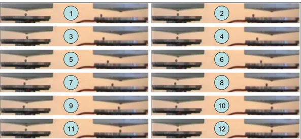
In Figure 9 the main significant frames of a centering test are shown: the object (a metallic sphere with a diameter of 1.2 mm) moves from its starting point in frame 1 to the final point (i.e. the central point) in frame 12.
1 2 3 4 5 6 7 8 9 10 11 12
Figure 9: Main significant frames of a centering test with the metallic sphere (d=1.2mm).
The experiments
In order to avoid preferential directions of motion and no axisymmetric electrostatic field, a preliminary set up put the platform horizontal to the ground and the upper electrode perpendicular to the platform. Then, the experiments have been performed in two different phases: the first set to select the best control parameters within the range shown in Table 1 and the second set to evaluate the centering performance of the tested microobjects in relation to humidity.
First set: selection of the best centering parameters
The experiments of the preliminary phase have been carried out with a humidity value of 50% HR for each type of microobjects. This value is the highest level in the humidity range considered in tests: since humidity is a well known parameter [6] that limits the motion of microparts, it has been important to evaluate what would have happened at the extreme environmental conditions.
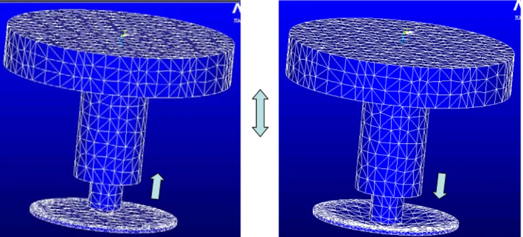
In the procedure used to select the best parameters, the vibration frequency was the same for all the objects and corresponded to the first own frequency of the platform found out with a FEM simulation: 2000Hz. The corresponding own mode is an axial mode (Figure 10) that allowed the object to be detached from the platform without radial components of motion.
Chapter 4 Developed Handling devices for microproducts
Figure 10: FEM simulation of the platform to find out the own frequencies.
Actually, the first own frequency is the best frequency for reducing the adhesion of parts to the platform [4]. Since adhesion forces and friction depend on dimension, shape, material and mass of the micropart [6][7], the selected vibration amplitude changes with the object. This vibration amplitude was selected within the range 1.5-18µm (with step of 1.5 µm) at 50% HR of humidity (adhesion forces and in particular surface tension are stronger when the humidity grows up), in absence of electrostatic field. The good vibration amplitude is the minimum value that allows microparts to be detached from the platform. Actually, the excessive shifting and bouncing of microparts is not allowed because the aim of the vibration platform is to reduce adhesion forces and friction without giving the microobject a preferential direction of motion.
Once identified the vibration frequency and amplitude, the other parameters have been selected on the basis of speed (voltage and the angle of the cone of the upper electrode) and centering precision (dimensions of the cylindrical and the prismatic protuberance). Because the electric field intensity depends on both the voltage and the distancebetween electrodes, the distance was kept constant and the voltage was changed. The distance between electrodes depends on the microobject and was set to 0.5 mm more than the higher dimension of the object in order to avoid the short circuit of electrodes in case of conductive microobjects. A glass plate upon the electrode platform would have decreased the risk of electric discharge [12] because it has a breakdown voltage much higher than air (3·106 air – 109 glass), but experiments showed that the polarization of glass reduces the motion of microparts (in particular dielectric parts).
In order to select the value of the voltage and the angle of the cone, the experimental procedure considered:
• level of humidity: 50% HR
• three conic angles of upper electrodes: 4°, 6°, 8° (without protuberance) • seven level of voltage: step 0.25 kV from 0.5 to 2 kV
Microhandling devices for the assembly of Hybrid Microproducts
The best values of voltage and conic angle are those that assure the higher centering speed.
Regarding to the upper electrode protuberance dimensions, the experimental procedure considered three types of prismatic protuberance and two kinds of cylindrical protuberance: cylindrical protuberance: d1=1mm, d2=0mm; d1=1mm, d2=0.5mm; d1=1mm, d2=1mm; prismatic protuberance: d1=1.5mm, d2=0.2mm, d3=0.5mm; d1=1.5mm, d2=0.7mm, d3=0.5mm;
The best dimensions of the protuberance are those that assure the higher centering precision.
Second set: evaluation of the centering performance
In the second experimental phase, the centering performance have been investigated in the humidity range 22-50% of HR using the parameters selected in the first stage.
Three sets of four centering tests were considered for each step of humidity (4HR step). Every set had four tests because in each one the start point of the object was a different cardinal point of the round platform to verify that there were no preferential directions of motion. Experiments have been carried out using the platform with the conic hole for spheres and the plane platform for cylinders.
Since experiments have not been performed in a white room and dust is recognized to be a factor limiting the mobility of microparts, the objects and the platforms have been accurately cleaned up with acetone before each test.
Experimental results
First set: The centering parameters
Apart from the vibration frequency of the platform, the best parameters depend on the various kinds of microobjects. The best parameters for the tested microobjects have been found out in the first experimental set and are reported in Table 3.
15 2000 1.5;0.5;0.2 8 1.6 2 cylinder 2 13.5 2000 1.5;0.5;0.2 8 1 2 cylinder 1 10.5 2000 1;0.5 8 1 1.3 sphere 3 7.5 2000 1;0.5 8 1.25 1,7 sphere 2 8.8 2000 1;0.5 8 1.25 1,7 sphere 1 A (µm) υ (Hz) d1d2d3 (mm) φ (°) V (kV) D (mm) Parameter Object
Chapter 4 Developed Handling devices for microproducts
Second set: the centering performance
The centering precision (i.e. the distance between the object center of mass and the axis when the vibration was deactivated) has not been reported because in all tests the spheres had a centering precision lower than the camera and the optical system resolution (50 µm). Actually, tests considered the object to be centered when the coordinates of its barycentre and those of the upper electrode axis differ 1 pixel (i.e. 50 µm) at most. Since overshooting and vibration are not considered as good centering, the object is centered correctly if it stays in central position at least for one second.
Figure 11 shows the centering average speed in the humidity range 22-50% of HR. As shown in the graphs and checked by ANOVA [13], humidity influences the motion of microspheres: actually, the centering speed decreases if humidity rises up.
0 0,2 0,4 0,6 0,8 1 1,2 1,4 22 26 30 34 38 42 46 50 humidity (HR) sp eed ( m m /s ) Spheres: Cylinders: glass d:1200 µm X steel d: 800 µm
+
steel d:1200 µm X steel d:1500 µm; h:1500 µm steel d:500 µm; h:1500 µm oFigure 11: Centering speed of tested microparts.
Under the same humidity conditions, the difference in the average speed of the various microobjects depends on their material, dimension, shape and mass.
Concerning the material, the steel sphere with a diameter of 1200 µm has a speed higher than the glass one of the same size. The mass difference between the two spheres would cause a greater acceleration of the lighter one, but adhesion forces (probably electrostatic ones due to the tribolectrification) are evidently much stronger in the case of glass rather than of steel. The steel sphere of 800 µm moves faster than the one of 1200 µm: spheres of the same material move a bit faster when their mass is lower but this speed difference is not pronounced because adhesion forces are the same on the two types of spheres. With regard to the cylinders, the one of lower mass is faster. In comparison with metallic spheres, cylinders have a lower speed because they have a contact surface with the platform wider than the spheres. Hence adhesion forces on cylinders are greater than on spheres.
Microhandling devices for the assembly of Hybrid Microproducts
Specific tests have been done to consider the dust effect on the centering test. In these tests, the object and the platform were not cleaned up with acetone before each set but only once per humidity step. The results have shown a lower speed (a reduction of 10-20% has been observed) without the centering precision was compromised.
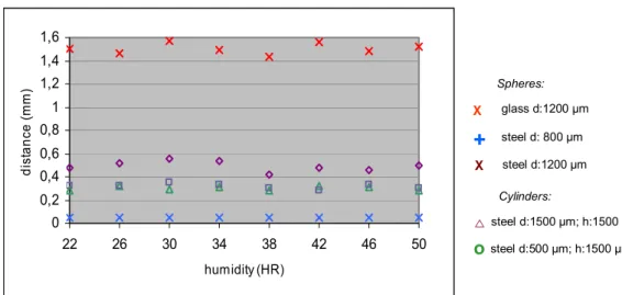
Figure 12 shows the centering stability (i.e. the shift of the object after the electrostatic field was switched off) in the humidity range 22-50% of HR.
0 0,2 0,4 0,6 0,8 1 1,2 1,4 1,6 22 26 30 34 38 42 46 50 humidity (HR) di st an ce ( m m ) Spheres: Cylinders: glass d:1200 µm X steel d: 800 µm
+
steel d:1200 µm X steel d:1500 µm; h:1500 µm steel d:500 µm; h:1500 µm oFigure 12: Centering speed of tested microparts.
The centering stability is not affected by humidity but it is related to the microcomponents material and, obviously, to the dimension of the platform conic hole.
The glass and the metallic spheres with the diameter of 1200 µm and the cylinders have a shift after the electrostatic field has been switched off. This phenomenon is pronounced for the glass sphere probably because the polarization persists longer in it than in the metallic one after the deactivation of the electrostatic field. Hence, during the capacitor discharge time this polarization makes the glass spheres attracted towards platform zones of opposite charge. If the electrostatic force overtakes the friction, the spheres are attracted towards these zones. Concerning the dimension of the hole in the platform, it is able to completely avoid the shift of the little metallic sphere only. A bigger hole would increase the centering stability of greater spheres, but it would probably gives problems for grasping. With regard to the cylinders, the centering stability is almost the same for the two types of cylinders.
Even if the centering precision is not very good, it is enough to allow the grasping of the object (except the glass spheres) by grippers, such as an electrostatic or an adhesive one, which moves in the theoretical position (i.e. the geometrical center of the device). This fact, as explained in § 4.2.2 in the section “Experimental results”, permits to grasp the component without recognizing before the real position of the object.
Chapter 4 Developed Handling devices for microproducts
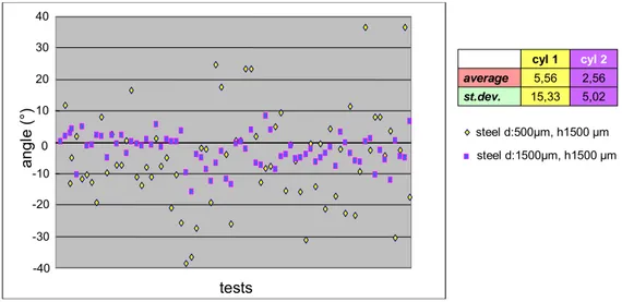
With regard to the orientation along a preferential direction, the results are shown in Figure 13. Since ANOVA checked that humidity did not influence the orientation capability, results are not reported in function of humidity.
-40 -30 -20 -10 0 10 20 30 40 tests ang le (° ) st.dev. 15,33 5,02 2,56 5,56 average cyl 2 cyl 1 steel d:500µm, h1500 µm steel d:1500µm, h1500 µm
Figure 13 : Orientation of the cylinders.
In spite of the electrostatic field that is maximum below the protuberance, tests reveal that cylinders do not completely align along the dimension d1 of the prismatic protuberance.
This fact shows that the alignment capability along the protuberance is not as strong as the centering capability. The same happens in the electrostatic microgrippers developed by Fantoni and Biganzoli [10]. Furthermore, scattering data in Figure 13 show how cylinders with a diameter of 1500 um have a higher centering capability than the little ones. This fact relates to the adhesion forces: vibration reduces adhesion forces more on the heavier cylinders.
Integration with grippers
In order to obtain a compact module of positioning and grasping, the electrostatic centering device has been provided with two kinds of grippers: an adhesive and an electrostatic gripper. These integrated grippers have been checked in a few qualitative tests.
Electrostatic gripper
The electrostatic gripper has been realized by increasing the potential difference between electrodes once the object was centered. Actually, if the axial electrostatic force overtakes gravity and adhesion forces, the object is attracted toward the upper electrode. A thin piece of glass has been interposed between the electrodes to avoid the metallic objects discharging when contacting the upper electrode. Therefore the object does not detach itself immediately and it is possible to move it elsewhere. The electrostatic gripper
Microhandling devices for the assembly of Hybrid Microproducts
has been tested in the grasping of the spheres: Figure 14 shows the grasp of the metallic sphere with diameter of 0.8 mm.
centering
detaching
grasping
Figure 14: Centering, detaching and grasping of a metallic sphere (d=0.8mm) with the electrostatic gripper integrated in the centering device.
Adhesive gripper
The adhesive gripper integrated in the centering device has a little hole (d=0.6 mm) in the upper electrode coaxial to the conic electrode axis. By a controlled dispenser of liquid, the resulting little drop is able to grasp the components even if it is not perfectly centered. Actually, the centering capability of the drop [14] permits the automatic centering of a microobject whose distance from the center is less than the drop radius.
This adhesive gripper permits to grasp spheres and cylinders but also complex shape objects as screws (Figure 15).
centering
drop dispensing
grasping
Figure 15: Grasping, drop dispensing and grasping of a metallic screw (d=0.5mm l=1mm) with the adhesive gripper integrated in the centering device.
Chapter 4 Developed Handling devices for microproducts
4.2.2 The electrostatic sorting device
[15]Aim of the device
The development of a sorting device, able to quickly separate and position many components at the same time, is an important issue in a microfactory. Actually, the use of microgrippers must face some problems: mechanical grippers need for well separated microparts, adhesive grippers sometimes grasp simultaneously more parts because of liquid bridges [16] and charge induction causes similar issues in electrostatic grippers [10]. The aim of the sorting device is positioning in a prearranged matrix components randomly placed in a workspace (Figure 16). Once positioned, components are ready to be grasped by a gripper without control: the gripper goes to the same positions where it finds the components.
initial random configuration final matrix arrangement
Figure 16: Aim of the electrostatic sorting device.
The electrostatic principle can be fruitfully used for a sorting device which is required to: • be insensitive to scale effects (compared to gravitational approaches that are not
suitable when adhesion forces become predominant);
• maintain a free area around the object in order to allow the component to be grasped [17];
• minimize the time for separating components (compared to stochastic approaches, usually slow [17]);
• have a high reliability in separating parts (avoiding cases of grouped components [16][18]);
• be used in standard, even if clean, industrial environment [18] (avoiding under liquid handling or clean rooms using);
• permit the simultaneous sorting of many components;
• avoid any feedback control in terms of final position of components.
The solution proposed is a reliable electrostatic sorting device able to generate a high number of energy minima towards which many parts are rapidly and simultaneously attracted.
Microhandling devices for the assembly of Hybrid Microproducts
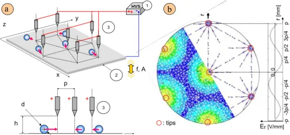
The experimental device
The sorter (Figure 17 a) consists of a High Voltage Supply (1), a vibrating platform (2), a series of electrode tips (3). The electrodes are arranged in a matrix pattern of pitch p and they are simultaneously connected to the HVS. The electrode tips have a distance h from the conductive platform and the applied voltage between the tips and the platform is V. The high voltage applied to this layout generates, on the entire platform, a continuous force field towards the tips. By the aid of the vibration that reduces adhesion and friction, the components are rapidly driven towards the tips axes where the electrostatic potential minima are. Er [V/mm] : tips -p -3p/4 -p /2 -p/4 p 3p/4 p/2 p/4 r r [m m] 0, 0
b
a
HVS +- 1 -p h y + + + d 3 x y z 2 3 f, AFigure 17: Scheme of the sorting device (a); Comparison between FEM and numerical analyses of the radial electrostatic field at z=d/2 for a hexagonal pattern (b).
The theoretical analysis of the electrostatic field
With the assumption that the force on components can be considered proportional to the unmodified electric field [10], a numerical and a FEM analyses have been performed. The numerical analysis is based on a simplified model where the tips have been approximated by thin cylinders, while the FEM used a complete model of the real device. However the results are totally equivalent and show the presence of an electrostatic field oriented towards the tips (Figure 17 b).
The device design depends on the electrostatic field configuration that is required to solve both sorting and positioning problems. Actually the optimal final position of components has to present only one component per tip with the microparts barycentre on the tip axis (configuration that maximizes the distance among microcomponents). No trapped components are allowed among others correctly positioned. Obviously, the field configuration assuring the requirements is obtained through a suitable geometry for the conductive elements of the global device.
Chapter 4 Developed Handling devices for microproducts
The chosen sorter has an equilateral triangle pattern repeated several times. The electrodes are located at the vertex of each triangle. This pattern minimizes, in comparison with others of the same pitch (e.g. the square one), the space among minima (Figure 18 a). As obvious, the pitch that avoids unwanted configurations (i.e. trapped microparts among others correctly positioned) depends on the handled microcomponents. Assuming that the microcomponents are spheres with a diameter d, the energy of the entire system is minimised in the configuration of one sphere per tip, that is the desired optimal sorting because it maximises the distance among components. Together with minimum energy solution, there are other configurations of possible equilibrium, even if not stable. These situations present spheres in contact and reduced free space among them. To prevent some spheres from remaining in these unwanted configurations, some design rules concerning pitch and vibration are necessary.
For example, since the field is nearly axial symmetric (Figure 17 b), the spheres C and D in Figure 18 b are subjected to an opposite electrostatic force field. To avoid this situation, it is sufficient that the spheres A and B, correctly positioned, push the sphere C out of equilibrium. Then, the electrostatic force acting on the sphere C exceeds the one on D, causing a correct sorting. To assure that, the tip axis must intersect the sphere C when the three spheres are tangent (Figure 18 a). It means to solve the inequation (1)
4
2
3
2
2 2p
d
d
p
<
∆
=
+
−
(1)whose upper solution (maximum pitch) is shown in (2)
(
)
d
d
P
=
+
≈
1
.
4
⋅
4
15
3
(2)Within this design (p=P), the other possible configurations of unstable equilibrium (as for example that in Figure 18 b-2) are extremely improbable because of the presence of vibration. Actually, vibration amplitude and frequency have to be selected among those able to alter the unstable configuration and to aid the spheres to assume correct positions. : electrode tip d C D p d B A 1) 2) ∆ p p a 1) 2) b
Microhandling devices for the assembly of Hybrid Microproducts
Thanks to sphere collisions and bouncing, a pitch greater than the theoretical one can be used in the real device as preliminary experimental results have confirmed. This fact is very important because it allows to increase the free space among the spheres.
Since the pattern of the electrodes repeats several times, the electrostatic field in the central zone of the device can be generally assumed to be that one of Figure 17 b. Conversely, at the boundaries it differs significantly. Because of the lack of symmetry, as theory predicts and experiments confirm, the reliability decreases when the external tips are considered (please refer to the following paragraph).
Experimental results
In experimental tests several spheres were positioned under the tips. Experiments were performed not only using randomly positioned spheres but also spheres arranged in various configurations as shown in Figure 19.
Figure 19: Some initial configurations of spheres.
Then, the electrostatic field and the vibration were activated in succession. In a few seconds (1s<t<5s) the microparts were sorted and positioned. Hence, the vibration and the high voltage were switched off. Preliminary tests were performed in order to determine the optimal set of all the parameters allowing a reliable positioning of one part [1].
The whole system was inserted in a controlled environment and tests were performed in a narrow range of humidity (HR=30-40%) and temperature (T=20-25°C).
The components tested in the experiments were conductive spheres with diameters varying from 1.2mm to 1.4mm. The experimental parameters were h=1.5mm, V=1200V and a vibration with f=1400Hz and A=10 µm. The pitch p of the tip pattern was 2mm. Four sets of tests with different number of spheres (14, 18, 23, 25) were performed by using a sorting device with 23 tips. Each set consisted of 20 tests.
A digital camera, with the axis perpendicular to the platform, was used to capture and analyse the microparts positions before and after the sorting. A tailored software, based on a commercial vision system, was used to recognise the components and to detect their centre of mass. The images before and after the sorting were analysed. The actual positions of the electrode tips were superimposed to the image of the sorted components. The software automatically extracted all the distances (a in Figure 20) between each
Chapter 4 Developed Handling devices for microproducts
centre of mass and the closest tip axis and the distances (b in Figure 20) among sphere centres. Electrode tips Component centre unsorted a I B B B B B B B B B B B B B B B B I I I I I I b
B: boundary electrode I: internal electrode
a b
Figure 20: Position of the spheres before (a) and after (b) the parallel sorting of 23 spheres per 23 tips.
These distances were used to calculate the number of components perfectly sorted (reliability in Table 4): it means separated (b>d, sorted in Table 4) and correctly positioned (a<d/2). In addition, the mean value and standard deviation for all the tips for each set (average distance and σ in Table 4) were computed.
The reliability, the average distance “a” and its standard deviation were also calculated for boundary (marked with B in Figure 20) and internal tips (marked with I in Figure 20). Table 4 shows the results concerning the tested device with 23 tips for each test set while the results about the sorting capability of boundary and internal tips (considering all the tests) are shown in Table 5.
Number of spheres Reliability (%) Average distance [mm] σ [mm] Sorted (%)
14 98 0.60 0.22 100
18 86 0.55 0.29 99
23 87 0.49 0.22 98
25 86 0.52 0.19 98
Table 4: Results obtained from the sorting device with 23 tips.
Tips Reliability (%) Average distance [mm] σ [mm]
boundary 83 0.56 0.26
internal 100 0.55 0.23
Table 5: Results obtained for boundary and internal tips.
The assumption of the distance d/2 to evaluate the correct positioning of spheres is due to considerations regarding the possible grippers to be used for grasping the sorted components. An adhesive gripper (Figure 21-a) has a drop with a radius comparable with
Microhandling devices for the assembly of Hybrid Microproducts
the sphere’s one. Therefore the gripper is supposed to be able to grasp the sphere when the maximum distance between the axis of the gripper and the centre of the component is d/2. An electrostatic gripper [10] presents nearly the same centering and grasping capability as the adhesive one. Moreover, they both pick up components from the top without needing free space among the spheres. Conversely a mechanical gripper (Figure 21-m) requires at least the space for its fingers.
d/2 d drop Theoretical position Actual position s a m Sphere to be grasped Unsorted sphere r
Figure 21: Adhesive gripper (a) and mechanical Figure 22: Sticking effects in grasping [16]. one (m) in the grasping of a sphere.
As it emerges from Table 4 (also checked by ANOVA), the reliability depends on the number of components to be sorted: actually, the reliability of the sorter increases when the number of components is much lower than the number of electrodes. This fact relates to two linked phenomena. First, when the ratio between the number of tips and spheres reduces itself, the available energy minima points per sphere decrease. Second, all the boundary tips (with a lower reliability) become necessary only when the number of spheres exceeds that of internal tips.
Furthermore the results of Table 5 confirm the theoretical prediction of the different reliability of internal and boundary tips. Whilst the reliability, or equivalently the sorting capability, is affected by the entire force field of the close tips, the average distance and standard deviation remain nearly the same because they depend only on the electrostatic field below each tip.
In conclusion, to correctly sort a certain number of spheres it is necessary to use a larger number of both spheres and tips that compensate the lack of reliability (always over 85%) of the electrostatic sorter. Another interesting result is that the number of unsorted components remains always lower than 2%, giving the device a very good sorting capability. These facts allow the use of the device to solve the important problem of multiple grasping [16].
Finally, tests demonstrated that the use of vibration is not necessary in dry environment (HR=30%). Actually the reliability of the sorter remained, also in these tests, over 85% and both average position and standard deviation were not significantly affected. Otherwise, when humidity increases, vibration becomes fundamental to overcome the adhesive forces.
Chapter 4 Developed Handling devices for microproducts
4.2.3 Grippers
The mechanical grasping devices
Even if in the micro domain adhesive effects make the use of mechanical grippers more difficult than in the macroworld especially for the releasing phase, mechanical grippers remain very versatile devices in terms of material, size and shape of the objects that is possible to handle with. The releasing phase, difficult if using gravity only, can use other forces in addition to gravity one (please refer to § 3.2.2)
Different types of mechanical grippers with two fingers have been designed and tested in the PhD research. The actuation chosen for these grippers was the piezoelectric one and the material selected for the grippers was harmonic steel that has a quite high yield strength (Sy=1000MPa).
The performance required to the developed gripper were: • self centering capability
• low cost • compact size
• good versatility (in terms of dimension and shape of handled microobjects) Design and simulation
The models of grippers designed are shown in Figure 23.
1 2 3 4 5
Figure 23: Mechanical grippers designed.
The grippers 1-4, normally open, have a gap between fingers of 1.4 mm and are actuated by pulling a force acting on their base (Figure 24 a). The model 5 is a gripper normally closed: the fingers open themselves when the basis is subjected to a tractive force (Figure 24 b). Because of the design of the grippers, the axial displacement causes the closing of the fingers in grippers (Figure 24).
Microhandling devices for the assembly of Hybrid Microproducts F Base Fingers Z X F Base Fingers Z X a b
Figure 24: mechanical grippers: working principle.
In order to select the best grippers in terms of fingers opening, FEM simulations evaluated (for each model) the maximum finger displacement for the yield stress (Figure 25).
Y rotation
Stress
yX displacement
x z
Figure 25: FEM simulations of model 4.
Since grippers have to be compact, the maximum dimensions of the gripper (model 3 in Figure 23) are 30 mm length and 10 mm width. Their thickness is 0.3 mm. In Table 6 are shown the optimized gripper dimensions and the performance in terms of maximum open/close fingers capability.
Chapter 4 Developed Handling devices for microproducts 10 4 0.66 (+) Gripper 5 17 7 2.2 (-) Gripper 4 28 10 1.8 (-) Gripper 3 25 10 0.7 (-) Gripper 2 25 10 0.30 (-) Gripper 1 Length (mm) Width (mm) closing (-) / opening (+) (mm) (for the yield stress) Gripper model
Table 6: Gripper features and performance.
The devices
On the basis of the performance shown in Table 6, the grippers 3-4-5 were realized. Actually, these models have a high open/close capability and an initial gap between fingers that lets them grasp objects in a wide range of dimensions. These grippers were realized by laser cutting and actuated (model 3-4) with a piezo stack. The piezoelectric actuator (1 in Figure 26) is pushed in contact with the gripper basis by means of a screw (2 in Figure 26). The same screw preset the axial position of the piezo stack setting the initial gap between fingers. The piezo stack allows an axial displacement of 0.2 mm in compression and 0.2 in extension by applying a voltage of 100 V.
2
1
Figure 26: Gripper 4 actuated by a piezo stack (1) and with the presetting screw (2).
Experimental test
A commercial micropositioner with 3 DOF (3 in Figure 27) was provided with the gripper 4 (1 in Figure 2) by means of the interface (2 in Figure 2)
Microhandling devices for the assembly of Hybrid Microproducts
3
2
1
Figure 27: 3 DOF micropositioner with the mechanical gripper and handled microbjects.
This system was used in pick and place tests of the cylinders and spheres shown in Figure 27.
In tests with spheres two releasing strategies have been followed: the simpler one that used gravity force only (a in Figure 28), and the other one that combines gravity and capillary forces (b in Figure 28). If humidity is lower than 40%, the gravity force (g) is enough to overcome the adhesion one (a). Actually, when humidity was quite high (more than 40% HR), often spheres stuck to the fingers. In this case, the releasing strategies made use of a drop of liquid (water or oil) in the releasing place. Capillary forces between the sphere and the drop (c) add themselves to the gravity (g): their sum is strong enough to overcome adhesion forces (a) between the sphere and the fingers, making possible the releasing of the object.
a g c Mechanical gripper Liquid drop a Mechanical gripper g a HR< 40% b HR> 40%
Figure 28: Releasing strategies of the spheres: by means of gravity only (a); by means of gravity and capillary forces (b).
Chapter 4 Developed Handling devices for microproducts
In Figure 29 the main significant frames of pick and place test of a sphere with a diameter of 0.8 mm are shown. The mechanical gripper grasps the sphere from place 1 and releases it (by exploiting gravity only) in place 2. The test was done with a humidity level of 30 % HR.
2
1
Figure 29: Pick and place of a metallic sphere with a diameter of 0.8 mm.
Pick and place of cylinders have considered peg in hole tests. In particular, the aim was the investigation of the backlash between the cylinder and the hole in peg in hole tasks. A plate with many holes with diameter of 0.50 mm +0.015/-0.006and cylinders with diameter of
0.49 mm +0.034/
-0.018 have been used for this purpose. As shown in Figure 30 the cylinder is
first grasped from hole 1 (d=0.75 mm), then self centered by exploiting the self centering capability of the mechanical gripper and finally inserted in the hole 2 (theoretical d=0.5mm). Under vision control, it has been possible to reach a theoretical clearance fit cylinder-hole with 10 µm of backlash.
Microhandling devices for the assembly of Hybrid Microproducts
2
1
Figure 30: Peg in hole test.
The adhesive grasping devices
A simple adhesive gripper has been designed and tested. The controlled releasing of a drop of water by means of a microdispenser permits to grasp microobjects by exploiting the capillary forces.
The adhesive gripper (supported by a 3 DOF commercial micromanipulator) has been tested in the pick and place of spheres (Figure 31). The spheres used in tests had a diameter in the range of 0.8-1.2 mm.
Figure 31: The 3 DOF micropositioner supports the adhesive gripper and the pick and place of a sphere with diameter 1.2 mm by the adhesive gripper.
Chapter 4 Developed Handling devices for microproducts
4.2.4 The electromagnetic positioning device
Aim of the device
The aims of the micropositioning device were the construction of a serial 2 DOF manipulator characterized by compact size and low cost. This manipulator had to be able to support a light gripper (e.g. an electrostatic or an adhesive gripper) for pick and place tasks. In addition, the system had to be easily actuated with a good repeatability even without feedback control.
The design of the electromagnetic positioner
The micropositioning system (Figure 32) is a 2 DOF robot where each degree of freedom is independent from the other. Actually the device has two independent elastic structures of polymeric material that are flexible in one direction (x or y) but nearly infinitely rigid on the other perpendicular direction (y or x). The 2 DOF are electromagnetic actuated by means of two magnets on the two axes. On the basis of the direction of the current in the coils, the magnets are pushed or pulled by the generated magnetic force.
In order to make the structure more compact, the second degree of freedom has been inserted into the free space of the first degree. This configuration allows a reduction of the height of the barycentre and consequently a more stable structure.
Permanent Magnet coil Y-leaf springs X-leaf springs coil Permanent Magnet x y z 0.2 12 Leaf spring
Microhandling devices for the assembly of Hybrid Microproducts
The theoretical analysis
In order to obtain clear results in terms of graphical aspect, the theoretical analysis refers to a structure with the second DOF put on top of the first one (Figure 33 a). This structure is equivalent in terms of stiffness to the one shown in Figure 32 .
The deformation in the X or Y direction of the parallel structure due to a force acting in the same direction can be evaluated by means of the equation in Figure 33 a. The elastic modulus of the flexible polymeric material was experimentally obtained by a tensile stress as shown in Figure 33 b.
3EJ
3Fl
s
=
F
s l -20 0 20 40 60 80 100 120 0 0,01 0,02 0,03 0,04 0,05 0,06 0,07 0,08 0,09 y = 4905,9x R2 = 0,9953 -20 0 20 40 60 80 100 120 0 0,01 0,02 E= 5000 N/mm2 b a2
1
x y zFigure 33: Numerical estimation of the displacement along Y due to an axial force F acting in the same direction (a); tensile stress to obtain the elastic modulus of the flexible polymeric
material (b).
Because of the chosen geometry of the leaf springs (Figure 32) that are slim in one direction (0.2 mm) and large on the perpendicular one (12 mm), the ratio between the two axial moments of inertia (Figure 34) allows the decoupling of the movement of each degree of freedom as checked by FEM analysis (Figure 35).
1 2 J1x<< J1y Fx J2y<< J2x Fy 711,1 ratio J2/J1 12,8 J1x=J2y 0,018 J1y=J2x x y z
Figure 34: Comparison of inertia momentums of the 2 DOF.
Chapter 4 Developed Handling devices for microproducts z x y z x y
b
a
Figure 35: FEM result for (a) the x displacement generated by a centred force (1N) located on the upper surface of the system and directed along x and (b) the y displacement generated
by a centred force (1N) located on the upper surface of the system and directed along y.
In this way, also a force not perfectly aligned along the x axis causes a considerable displacement along the x direction and an infinitesimal one in the Y direction: Figure 36 b shows the displacement of the structure for a force located on the upper surface of the system at a distance d=1mm (Figure 36 a) from the symmetry plane.
x y z dx c b a 1 2 x y z
Figure 36: FEM results concerning the displacements generated by a force (1N) along y located on the upper surface of the system at a distance d=1mm from the symmetry plane.
This fact is very important because the first DOF necessary works with a misaligned force when the second moves from the initial position. With refer to Figure 36 c, when the second DOF of the micropositioner moves in the X direction of dx, the magnetic force in the Y direction does not act in the centre of the structure but is misaligned of the value dx.
Microhandling devices for the assembly of Hybrid Microproducts
The experimental characterization of the prototype
The prototype of the micropositioner provided with an adhesive gripper (1) is shown in Figure 37: in the figure it is possible to observe the coils (2 & 3) and the leaf springs (4 & 5). The global volume of the device is 45x45x28 mm3.
1
2
3
4
5
y x zFigure 37: 2 DOF Electromagnetic Micropositioner.
The coil 3 has a rectangular shape to allow the displacement in the X direction. In the working range along X, this coil assures a quite constant magnetic induction so that the force acting on the magnet does not change in the different x positions the device assumes. The results are the same displacements along Y with the same current when the magnet axis is aligned (s=0) or misaligned (s=0.5 ; s=1) with the axis of the coil 3 as shown in Figure 38. In this figure, s is the distance between the axis of the coil 3 with the axis of the magnet.
Chapter 4 Developed Handling devices for microproducts -3 0 3 0 50 100 150 200 tests d is p la cem en t (m m ) s= 0 mm s =0.5 mm s =1 mm
Figure 38: Displacement along Y axis with two level of current when the axis of the coil 3 is aligned (s=0) or misaligned (s=0.5;1) with the axis of the magnet.
In order to limit overshooting and vibration, an electronic circuit controls the current flow in the coil during the transient phase avoiding the current step (Figure 39).
-3 -2 -1 0 1 2 100 200 300 400 frames d 3 [mm] pull push [25 frames/sec]
Figure 39: Displacement of the structure along the X axis with the current flow controlled by means of the electronic circuit.
Tests on the prototype have evaluated the hysteresis and the repeatability precision: the device was subjected to 900 pull cycles and 900 push-pull cycles. The results are shown in Figure 40: a low hysteresis and a repeatability precision (maximum positioning difference) of 50 um have been noticed.
Microhandling devices for the assembly of Hybrid Microproducts -1 -0,5 0 0,5 1 300 600 900 cycles(n) di sp la ce m en t (m m ) pull - push pull
Figure 40: Hysteresis tests.
In conclusion, the developed device lets a workspace of 6 x 2 mm2 with a linear relation between current and position (Figure 41) and a position repeatability of 50 µm. This allows the use of the system for pick and place tasks of microobjects in a little workspace without a need of feed back control.
Y (mm) X (mm)
- i
1x I1x -I2x I2x -I1y -I2y I1y I2y I1x -I1y -I1x -I1y I2x I2y I2x -I2y -I2x -I2y -I2x I2y- i
2xi
1xi
2xi
2Y (0,0)i
1Y- i
1Y- i
2Y-i
1X;i
1Yi
1X;i
1Y-i
2X;i
2Yi
2X;i
2Y-i
1X;-i
1Yi
1X;-i
1Yi
2X;-i
2Y-i
2X;-i
2Y 6 2L2
L1
Chapter 4 Developed Handling devices for microproducts
References
[1] Porta, M., Santochi, M., 2006, An electrostatic Centering Device for Microcomponents, 1st CIRP International Seminar on Assembly Systems, Stuttgart, 15-17 November 2006.
[2] Gengenbach, U., Boole, J., 2000, Electrostatic feeder for contactless transport of miniature and Microparts, Microrobotics and Micro-manipulation, Proceeding of SPIE, pp.75-81.
[3] Shu, L.-H., Lenau, T.-A., Hansen, H.N., Alting, L., 2003, Biomimetics applied to Centering in Microassembly, Annals of the Cirp, 52/1, pp.101-104.
[4] Böringer, K.-F., Cohn M., Goldberg K., Howe R., Pisano A., 1998, Parallel microassembly with electrostatic force fields, Proceedings of IEEE International Conference on Robotics and Automation, pp. 1204-1211.
[5] Fantoni, G., Santochi, M., 2005, A modular contactless feeder for microparts, Annals of the CIRP, vol.54/1.
[6] Fearing, R.-S., 1995, Survey of sticking effects for micro parts handling, IEEE/RSJ International Workshop on Intelligent Robots & Systems (IROS), Pittsburgh.
[7] Arai, F., Ando, D., Fukuda, T., Nonoda, Y., Oota T., 1995, Micro Manipulation Based on Micro Physics -Strategy Based on Attractive Force Reduction and Stress Measurement-, Proceeding of IEEE/RSJ Conference on Robots and Intelligent Systems 2, pp.236-241.
[8] Fantoni G., 2003, Assembly of mini and microparts: development of an electrostatic feeder, Proceedings of the 6th A.I.Te.M. International Conference, Gaeta, Italy, September 8-10, pp. 352-366.
[9] Desai, A., Lee, S.W., Tai, Y. C., 1998, A MEMS Electrostatic Particle Transportation System, The Eleventh Annual International Workshop on Micro Electro Mechanical Systems, pp. 121-126.
[10] Fantoni, G., Biganzoli, F., 2004, Design of a novel electrostatic gripper, International Journal for Manufacturing Science and Production, 6/4, pp.163-179.
[11] Geiger, M., Egerer, E., Enfel, U., 2002, Cross Transport in Multi-Station Former for Microparts, Production Engineering, IX/1, pp.101-104.
[12] Fantoni, G., Santochi, M., 2004, A contactless electrostatic device for linear movement of mini and microparts, Proceedings of the International Conference on Intelligent Manipulation and Grasping, Genoa.
[13] D.Montgomery, 2000, Controllo statistico della qualità, ed.McGrwHill (in Italian).
[14] Lambert, P., Seigneur, F., Koelemeijer, S., Jacot, J., 2006, A case study of surface tension gripping: the watch bearing, Journal Of Micromechanics And Microengineering vol.16, pp. 1267-1276.
[15] Fantoni G., Porta, M., Santochi, M., 2007, An electrostatic sorting device for microparts, Annals of the CIRP vol. 56/1.
[16] Lambert, P., Valsamis, J.-B., Seigneur, F., Koelemeijer, S., Delchambre, A., Jacot, J., 2006, Surface Tension Gripping Applied to a Mesoscopic Case Study, 1st CIRP International Seminar on Assembly Systems, Stuttgart, Germany, pp.153-158.
Microhandling devices for the assembly of Hybrid Microproducts
[17] del Corral, C., Zhou, Q., Albut, A., Chang, B., Franssila, S., Tuomikoski, S., Koivo, H.N., 2003, Droplet Based Self-Assembly of SU-8 Microparts, 2nd VDE World Microtechnologies Congress, Munich, Germany, pp.293-298.
[18] Böhringer, K. F., Srinivasan, U., Howe, R. T., 2001, Modeling of capillary forces and binding sites for fluidic self-assembly, The International Conference on Micro Electro Mechanical Systems, pp.369-374.

![Figure 11 shows the centering average speed in the humidity range 22-50% of HR. As shown in the graphs and checked by ANOVA [13], humidity influences the motion of microspheres: actually, the centering speed decreases if humidity rises up](https://thumb-eu.123doks.com/thumbv2/123dokorg/7293934.86217/11.892.179.754.369.635/centering-humidity-influences-microspheres-actually-centering-decreases-humidity.webp)