79
5 New feeding techniques for
circularly-polarized microstrip
antennas
Recent years have seen a significant exploitation of printed antenna technology for the realization of planar antennas for base stations (or access points) and subscriber units (CPE, customer premises equipment) of wireless communication networks, as for example wireless local networks (WLANs) at the 2.4 GHz ISM band (IEEE 802.11b/g), WiMAXTM systems in the 3.3-3.8 GHz frequency range, and high-data rate communications at 5-6 GHz (Hiperlan, IEEE 802.11a). Indeed, microstrip antennas are characterized by low profile, light weight, ease of construction, and high flexibility in designing shaped-beam and multiband antennas. As already discussed in Chapter 1, these are useful features also for NF focused arrays [5]-[8].
A common feeding technique for wideband antennas is that based on slot-coupling, where a microstrip line is coupled to the radiating patch through a slot in a metallic ground plane, as first proposed by Pozar [81]. Slot-coupled patches can exhibit a quite large impedance bandwidth at the cost of an affordable construction complexity, and allow for more space for the feed network of microstrip fed arrays (the latter being an important need especially for dual-polarized dense phased arrays [82]). Moreover, the metallic ground plane where slots are realized prevents the spurious radiation from the feed network and then reduces the amplitude of the cross-polar components.
In this context, a novel feeding technique for dual-polarized slot-coupled patch antennas, where the patch and the feeding line are coupled through a resonant square ring slot has been presented in [17]-[19]. A square patch is coupled to a pair of microstrip feed lines by a square ring slot realized in a metallic ground plane, and both feed lines are on the same side of a single-layer substrate. This chapter describes as the
80
above feeding technique can be effective in realizing single-feed and dual-feed circularly polarized antennas [20]-[26]
5.1
Circularly polarized antennas
Circularly polarized (CP) antennas are widely used in many communication systems, since they are able to provide radio links which result to be independent of the relative transmitter and receiver positions, and to reduce multipath effects. Several different layouts have been proposed to excite the two orthogonal fundamental modes of a patch antenna. In this respect it is worth mentioning the diagonal-fed nearly square patch, the corner-truncated patch and the square patch with peripheral cuts or with tuning stub [83]. As far as microstrip arrays are concerned, the above solutions exhibit all the advantages of a single feeding technique, but they guarantee a 3 dB Axial Ratio (AR) fractional bandwidth less than 2%. Better CP performance can be achieved with CP aperture-coupled patch antennas, which can be classified into dual-feed and single-feed solutions.
The dual-feed solution guarantees better performance in terms of the AR bandwidth [84], since an additional circuit is used to guarantee the required frequency-stable 90° phase difference. To show the working principle and the radiation properties of the proposed slot-coupled feeding technique, prototypes operating in the 3.3-3.8 GHz WiMAXTM frequency band have been realized and characterized [20]-[22]. A drawback in a dual-feed technique is represented by a wide space of implementation for the feeding line.
Indeed, the single feed configuration is preferred whenever the patch has to be used in a compact array configuration (i.e. NF focused array), since it can be treated as any linear polarized patch [85]. As consequence a novel single-feed CP patch, based on the novel slot-coupling technique is here proposed [24]-[26].
5.2
Single-feed CP square ring slot patch antenna
The antenna stack-up and geometry are illustrated in Fig. 5.1 for 3.3-3.8 GHz WiMAXTM applications. The antenna layout is based on the new slot-coupling configuration and the circular polarization is achieved by introducing some simple modifications of the square ring and patch geometries (namely a couple of meanders and slots).
A 50Ω feeding line is printed on a Rogers RO4003 dielectric substrate (εr=3.55 (is the recommended value for simulations, the real value is εr=3.38), tgδ=0.0027) and is coupled to the patch through a square ring slot etched on the opposite side of the laminate. An FR4 substrate (εr=4.4, tgδ=0.02) on which the square patch is printed, is placed at a distance of 11mm (air gap). Moreover, an aluminum ground plane is located
81
at a distance of almost a quarter of wavelength from the lower substrate (again they are separated by an air gap), to minimize the antenna back radiation.
It is worth noting that the use of a meandered slot has been proposed in [86] to obtain circular polarization in the case of a printed ring slot antenna. It suggested us to introduce the same kind of perturbation in the original square ring slot structure [17]. To preserve the antenna symmetry, two identical meanders have been added on two opposite sides of the square ring (A configuration, Fig. 5.1). Also, to satisfy both reflection coefficient and AR requirements, the following geometrical parameters have been optimized: slot width and length, meander width and length, meander-slot width. Simulations results have been performed with Ansoft DesignerTM.
Although the meanders added to the square ring slot are adequate to excite a CP field, AR performance can be further improved by adding a couple of cuts along the patch border (B configuration, Fig. 5.2). Numerical simulations have shown that the cuts must be realized in the plane orthogonal to that one containing the slot meanders. Both width and length of the above slots have been optimized. It is worth noting that the layout shown in Fig. 5.1-Fig. 5.2 can radiate Right Hand Circular Polarization (RHCP), while a Left Hand Circular Polarization (LHCP) can be achieved by simply feeding the patch at the symmetric corner with respect to the yz plane. The CP antenna in Fig. 5.2 has been fabricated and experimentally tested, The prototype size is 14x14 cm2 (Fig. 5.3).
Antenna prototyping and characterization has been carried out in collaboration with the University of Oviedo, Spain.
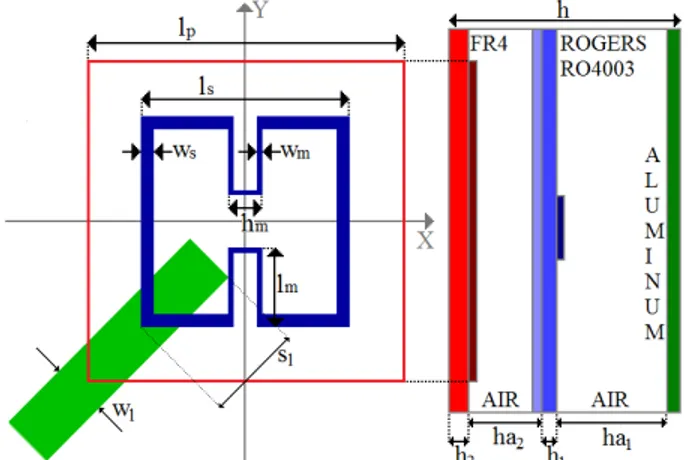
Fig. 5.1 - Antenna layout and stack up for a CP patch with a meandered slot (A configuration): lp=21 mm,
ls=13 mm, ws=0.8 mm, wl=3.6 mm sl=6 mm, ha1=22 mm, h1=1.524 mm, ha2=11 mm, h2=1.6 mm, lm=5 mm,
82
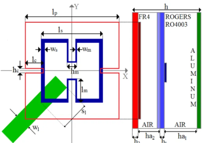
Fig. 5.2 - Antenna layout and stack up for a CP patch with a meandered slot and patch peripheral cuts (B
configuration): lp=21 mm, ls=13 mm, ws=0.8 mm, wl=3.6 mm sl=6 mm, ha1=22 mm, h1=1.524 mm, ha2=11
mm, h2=1.6 mm, lm=5 mm, wm=0.3 mm, hm=2 mm, lc=4.25 mm, hc=1 mm.
Fig. 5.3 - Antenna prototype (14x14 cm2) for the B configuration.
5.2.1 Antenna performance
The antenna reflection coefficient for both the first solution with the only meandered slot (A configuration) and that with the meandered slot and the patch peripheral cuts (B configuration) is plotted in Fig. 5.4. For both configurations, the simulated impedance bandwidth (reflection coefficient less than -10dB) is of about 22%. The measured reflection coefficient for the B configuration is shown in the same figure. A frequency band shift towards upper frequencies is apparently observed, due to prototype tolerances (nevertheless impedance bandwidth is of about 24%, as for the simulated results). The simulated HPBW at 3.55 GHz is 84° and 86° for the A and B configurations, respectively, in both vertical and horizontal planes. The measured HPBW is of 87° in agreement with the simulations. The prototype exhibits a peak gain of about 8 dB gain at 3.65 GHz and gain variations are less than 0.6 dB in the 3.3-3.8 GHz frequency band.
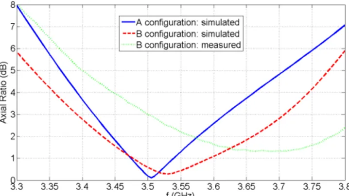
The advantage provided by the slotted patch (B configuration) is clear from Fig. 5.5, which illustrates the AR versus frequency in the broadside direction, for both
83
configurations. The A configuration exhibits a simulated 3 dB AR band of 5.6%; in particular, the AR results to be below 8 dB in the whole WiMAXTM frequency band. The B configuration exhibits a simulated 3 dB AR band of around 9% and the AR is less than 6 dB in the WiMAXTM frequency band. The measured AR on the prototype has a maximum (8 dB) at the lower frequency band (3.3 GHz) and a minimum (1.3 dB) at around 3.7 GHz, in agreement with the previously mentioned frequency shift observed for the reflection coefficient (Fig. 5.4).
Fig. 5.4 - Reflection coefficient: simulated A configuration (solid line), simulated B configuration (dashed
line) and prototype (dotted line).
Fig. 5.5 - Axial Ratio versus frequency at the broadside direction: simulated A configuration (solid line),
simulated B configuration (dashed line) and prototype (dotted line).
The measured 3 dB AR fractional band is around 9%. The AR performance as a function of the angle (angle measured from the broadside direction) is shown in Fig. 5.6. Data are relevant to the frequency of minimum value of AR, with reference to both the =0° and the =90° radiation planes. The simulated 3 dB AR beamwidth for the B configuration is about 81° in the =0° plane and 75° in the =90° plane, while the measured 3 dB AR beamwidth is 63° and 68°, respectively.
84
Fig. 5.6 - Axial Ratio versus the angle in =0° (no markers) and =90° (circle markers) planes for the
simulated B configuration (dashed line) and the measured one (dotted line).
5.3
Single-feed CP square ring slot stacked patch antenna
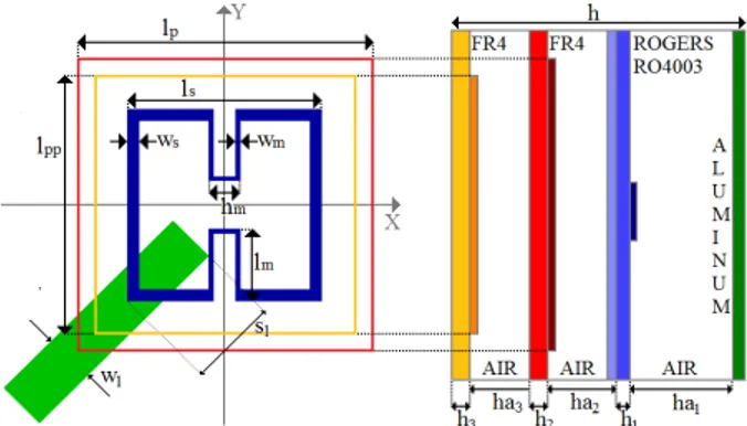
It can be shown that both AR and impedance bandwidth performance of the A configuration can be improved by adding a stacked patch. All the parameters for the new configuration (Fig. 5.7) have been optimized to meet specifications for a 3.3-3.8 GHz WiMAXTM antenna (C configuration). The driven patch size is 26x26mm2, while the parasitic patch is quite smaller: 20.5x20.5mm2.
Fig. 5.7 - Antenna layout and stack up for a CP patch with a meandered slot and a stacked patch (C
configuration): lp=26 mm, lpp=20.5 mm, ls=13.5 mm, ws=1 mm, wl=3.6 mm sl=6.3 mm, ha1=22 mm, h1=1.524
mm, ha2=11 mm, h2=1.6 mm, ha3=16 mm, h3=1.6 mm, lm=5.2 mm, wm=0.3 mm, hm=2.1 mm.
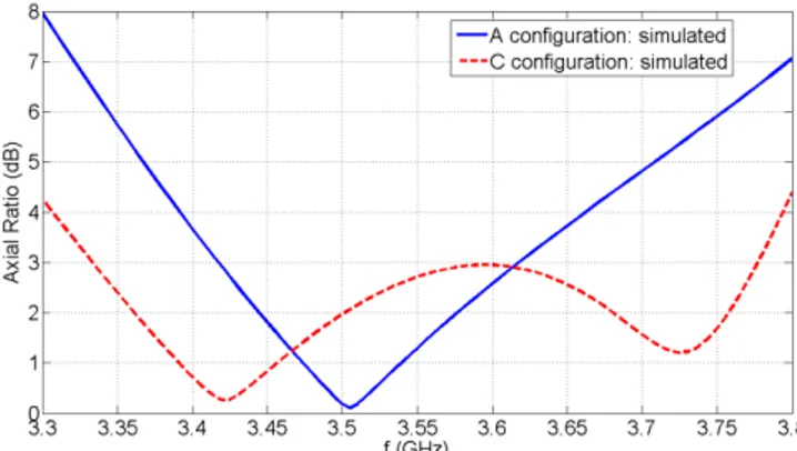
As expected, the simulated reflection coefficient bandwidth (shown in Fig. 5.8) increases up to 25% thanks to an additional resonance introduced by the stacked patch. The above result has been confirmed by measurements on antenna prototype in Fig. 5.9. The latter exhibits a peak gain of about 8 dB gain at 3.55 GHz and gain variations are less than 1 dB in the 3.3-3.8 GHz frequency band. By a careful antenna design and optimization it was possible to get a double resonance also in the AR curve (Fig. 5.10).
85
The AR is less than 4.4 dB in the whole 3.5 GHz WiMAXTM band and the 3 dB AR bandwidth increases up to 12.4%.
Fig. 5.8 - Reflection coefficient: simulated A configuration (solid line), simulated C configuration (dashed
line).
Fig. 5.9 - Antenna prototype (14x14 cm2) for the C configuration.
Fig. 5.10 - Axial Ratio versus frequency at the broadside direction: simulated A configuration (solid line),
86
5.4
Conclusions
A novel configuration for a wideband circularly polarized square ring slot microstrip antenna has been presented. The outstanding CP performance has been shown through the design, fabrication and experimental characterization of a CP patch for WiMAXTM applications in the 3.3-3.8 GHz frequency band. Measurements on a prototype have shown that an impedance bandwidth up to 24% (Reflection Coefficient less than -10dB) and a 3 dB AR bandwidth as higher as 9% can be achieved, the latter performance representing a remarkable improvement with respect to other CP single-patch configurations. In spite of an additional laminate (stacked patch), a 3 dB AR bandwidth of 12.4% can be reached too.