10
C
HAPTER
2
G
LASS
F
AÇADES
D
EFINITION
“If we want our culture to rise to a higher level, we are obligated for better or for worse, to change our architecture. And this only becomes possible if we take away the closed character from the rooms in which we live. We can only do that by introducing glass architecture, which lets in the light of the sun, the moon, and the stars.”
Bruno Taut
2.1 F
AÇADE
R
EQUIREMENTS
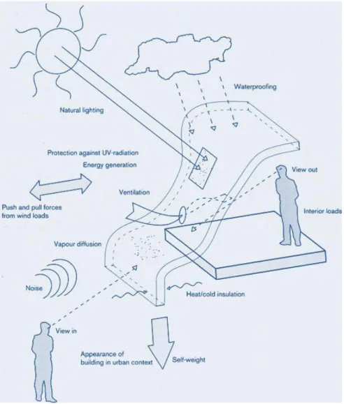
The external “skin” of a building can be described asa complex andmultifunctionalfilter between the external environment and the inside of the building itself. Before addressing today’s glass façade construction, it is important to call to mind the different functions that a façade serves. The following table summarises the functions of a façade and shows the complexity of the requirements to be fulfilled [8].
Determine the appearance of the building and its relationship with its surroundings, with the separation of the interior spaces of the building from the outside;.
Resist the penetration of rainwater, wind, and handle undesired humidity from within and without;
Allow and regulate the distribution of energy flows between the internal and the external of the building system;
Allow and regulate the natural light and visibility, provide views to the inside and outside, while protecting from the sun at the same time;
Provide insulation against heat, cold and noise, control the ventilation of interior
spaces, and can facilitate energy generation;
Provide the transmission of permanent loads (self-weight) and accidental loads (wind, earthquake and impact);
In Italy, the façade requirements are listed in UNI 7959:1988, which agrees with the ISO 7361:1986, Performance standards in building - Presentation of performance levels of facades made of same-source components. The standard provides an analysis of the
11
requirements of the vertical side walls (Fig. 1) in relation to the condition of use and it can be used as a reference for the design, production, construction and use of components for vertical external walls.
The list of requirements can be used as a reminder list of documents in the preparation of specifications, as a guide for the offer of supplies, or to define criteria for monitoring and preliminary acceptance, so the drafter of these documents must indicate the performance to be considered and possibly their hierarchical order.
Fig. 1 Façade Functions (EPFL Courtesy).
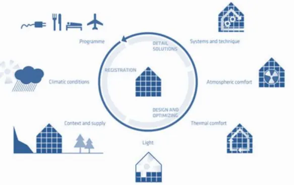
Such requirements need to be considered during all phases of the façade design and construction process: during the conceptual phase, while working on the principles of construction, during detailing and lastly during construction (Fig. 2).
12
Fig. 2Façade Requirements during Design and Construction Process.
In addition, the building envelope is an important field for experimentation and of novel construction techniques and materials [13]. Basically the goal is to have a structure that is as simple as possible, that carries out all these functions and that is adaptable to changing factors. It should be an adaptive envelope similar to the human skin, fulfilling several functions of the body. Therefore a façade is currently identified as a "skin", a “curtain", "envelope", which are variations of the same theme. Though often taken as synonyms, these terms refer to different solutions, both from a formal and a technological point of view, since that the stratigraphy of a traditional wall can now be replaced by endless variations.
At the technological level, contemporary architecture is focusing on industrialized façade systems that meet all the functional requirements whilst retaining lightness and modernity [31]. The prefabricated construction, applicable to the anchoring system and to the external coating, allows to obtain the separation of the layers and the specialization of the functions. The dismantling of the elements, achieved with the techniques of dry installation, facilitates their installation, the local replacement in case of breakage, as well as the recyclability of components in a sustainable way.
From the formal point of view, the definition and the role of façade in contemporary architecture is even more complex: the dialectic separation that involved the use of the
13
envelope to “mask” the parts of the building, or on the contrary, to exalt them, seems to be no more applicable tout court to contemporary architectural design. Categories as fullness/emptiness, mass/lightness, opacity/transparency, have evolved and now present ambivalence and unusual design variations, often due to the use of novel materials or of traditional materials used in innovative ways [35].
In such complex context, the use of glass as a façade material has increased significantly and has produced numerous systems and new smart materials.
Transparency, that is often modulated and "denied", is the key element of contemporary architecture. The openings in the façade can be much larger because of the possibilities offered by new glass manufacturing techniques, to the creation of entirely “glass walls” [65]. The need for technical and architectural glass surfaces, increasingly large and free of metal supports, profiles and frames, has led the industry to develop and produce innovative technologies and construction systems. Whichever glazing system is used for the façade, the key to the success of any glass façade installation project is the close collaboration between the designer, façade consultants and technical team [32]. Quality procedures give full control throughout the enquiry stage, the design process, glass processing, fabrication of the framing system, contract management and installation. This teamwork brings together and balances aesthetic objectives with functional performance and quality in terms of:
STRUCTURAL STABILITY
Fig. 3 MUSE, designed by Renzo Piano in Trento. THERMAL INSULATION
REDUCTION IN SOLAR HEAT GAIN
LIGHT TRANSMITTANCE
SOUND REDUCTION
WEATHER RESISTANCE
To achieve this “synergy”, all the figures involved in the design and construction process should, since the early of stages of the project, set out objectives, have the awareness of the problems associated with the use of glass and evaluate the technical solutions that may be available. Since it is not possible to have an omniscient knowledge of such topics, first it is
14
appropriate to gain the correct terminology, as stated in codes and regulations, in order to appropriate the framework to classify and to understand the general operation of the basic façade types.
Such approach can help to combine design and functional objectives through access to a comprehensive range of architectural glass, framing and glazing systems.
2.2 S
TANDARD
R
EFERENCE
Glass façades are one of the most applied envelope constructions today. Glass façades differ from traditional windows primarily because they are not included in a load-bearing external solid wall, but they themselves are a no load bearing external wall. This definition, although may appear obvious, clearly represents the distinction between these two different elements of the transparent building envelope and immediately show the behaviour of and curtain wall constructions for glass façades in respect of the whole building. Independently attached to the primary load bearing structure of the building, curtain walls protect the building’s interior from external climate condition and allow great design freedom [31].
Currently there is no single standard for the glass envelope, rather it is possible to identify a framework of complex and technical norms and product standards that governs the design and the production for glass envelope and its components.
EN 13830 Curtain walling. Product standard.
EN 12152 Curtain walling. Air permeability. Performance requirements and classification.
EN 12153 Curtain walling. Air permeability. Test method.
EN 12154 Curtain walling. Watertightness. Performance requirements and classification.
EN 12155 Curtain walling. Watertightness. Laboratory test under static pressure. EN 13050 Curtain Walling. Watertightness. Laboratory test under dynamic
15
EN 13051 Curtain walling. Watertightness. Site test.
EN 13116 Curtain walling. Resistance to wind load. Performance requirements EN 12179 Curtain walling. Resistance to wind load. Test method.
EN 12631 Thermal performance of curtain walling -- Calculation of thermal transmittance.
EN 14351-1+ A1 Windows and doors. Product standard, performance characteristics. Windows and external pedestrian doorsets without resistance to fire and/or smoke leakage characteristics.
EN 1026 Windows and doors. Air permeability tests. EN 1027 Windows and doors. Water penetration tests. EN 12207 Windows and doors. Air permeability. Classification EN 12208 Windows and doors. Watertightness. Classification
EN 12210 Windows and doors. Resistance to wind load. Classification EN 12211 Windows and doors. Resistance to wind load. Test method
EN ISO 10077-1 Thermal performance of windows, doors and shutters - Calculation of thermal transmittance - Part 1: General
The glass façade systems that are currently employed in the construction industry are regulated by the product standard concerning general curtain walls. For the purposes of the present study, it seemed useful to first understand the classification proposed by such product standard. Although this classification is not exhaustive and cannot describe all the existing types, it represents a first cognitive approach of primary importance to know the reference glossary.
Specifically, the European Standard EN 13830:2003 "Curtain walling - Product standard" specifies the characteristics of curtain walling and provides technical information on the varying performance requirements which apply throughout Europe, the test criteria and sequence of testing for the product, in order to demonstrate conformity. EN 13830 covers fire performance, weathertightness, wind loading, other applied loads, impact and thermal
16
transmittance. The standard contains criteria, procedures and methods for the verification of “essential characteristics” of façades, in particular as regards the essential requirement “safety in use”.
Two different terms are usually used to identify the light curtain systems: curtain walling and cladding.
Curtain walling is a form of vertical building enclosure which supports no load other than
its own weight that of secondary components and the environmental forces which act upon it. Although the term is sometimes restricted to metal framed curtain walls, the above definition embraces many different construction methods and materials including non-load bearing precast concrete.
Cladding is an all-encompassing term for the external skin of a building which keeps out
the weather and provides the building aesthetic. In low-rise buildings it may support its own weight but self-weight and wind loading are normally transferred to the structural building frame. It may form the full thickness of the vertical envelope of the building but can simply be the outer layer with additional layers providing insulation and the internal lining. There are many available types of cladding (profiled metal systems, small or large cladding panels), some of the categories are clearly defined but others cover a range of options and some variations could be considered to fall in more than one category. The distinction between curtain walling and some other cladding types is particularly blurred.
Curtain walling is not a product which can be completed in all respect within a manufacturing area, but is a series of components and/or prefabricated units which only become a finished product when assembled together on site. The standard can be applied to the whole of the curtain walling, including the flashing, closures and copings.
With the publication in the Official Journal of the European Union C263, dated 26.10.2004, of the product standard EN 13830 Curtain walling – Specification, the process of the CE marking for curtain wall systems is officially started on. The EN 13830 is under review by the TC 33/WG6. A revised product standard is being drafted and expected to be published early in 2014. The new version contains a specific annex (D) directed to the use of Eurocodes "Resistance to actions: guidance on the use of Eurocodes" and a specific annex concerning
17
the behaviour to the earthquake, annex E "Resistance to seismic action". The revised standard has an extended scope to include durability in addition to the performance characteristics described in the previous version.
The current EN 13830 defines the curtain wall as “an external vertical building enclosure
produced by elements mainly of metal, timber or plastic”. This standard applies to curtain
walling “ranging from a vertical position to 15° from the vertical, onto the building envelope.
It can include elements of sloping glazing contained within the curtain wall”. Therefore glass
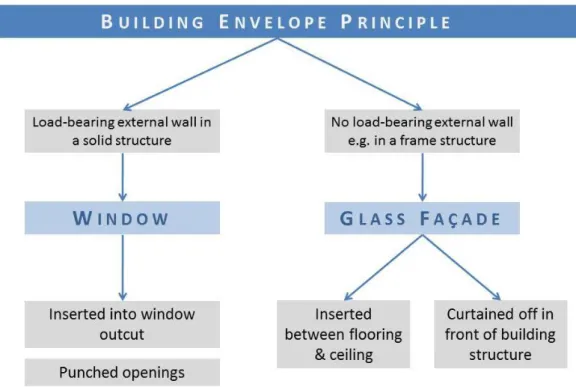
façades in Europe can be analysed and classified using European Standard EN 13830. Curtain walls perform all the functions of an exterior wall, except of the support of vertical loads transmitted by the decks: this function is performed exclusively by the vertical structures of the building. The curtain walls, as being "carried" by the building structure, do not contribute to its stability. Such definition clearly explain the different role of “windows” and “façades” in the overall functioning of the building envelope (Fig. 4).
Fig. 4 Window versus façade characteristics (Image by the Author).
The terminology and definitions applied in EN 13830 are listed in prEN 13119 Curtain Walling – Terminology, which definitive version is EN 13119:2007, as follows:
18
CURTAIN WALLING Generally consists of a grid of horizontal and vertical bearing
elements.
STICK CONSTRUCTION Light carrier framework of site assembled components supporting
prefabricated opaque and/or translucent infill panels.
UNITISED CONSTRUCTION Pre-assembled interlinking storey height or multi-storey height
modules, complete with infill panels.
SPANDREL CONSTRUCTION Pre-assembled interlinking part storey height modules, completed
with infill panels.
CURTAIN WALLING SYSTEM Collection of components from which a curtain walling kit may be
created for subsequent installation on a building. It can give rise to one or more different kits.
CURTAIN WALLING KIT Collection of components or prefabricated units which, when
installed in a building, form a curtain wall.
Curtain walling is a continuous and light façade, that can ensure all the functions (UNI 7959/ISO 7361), including the resistance to weathering, the safety in use, the safety and environmental control, but that does not contribute to the load-bearing characteristics of the building structure. The exclusion of the support function for vertical loads has allowed the realization of systems of light façades, with metal frames and opaque or transparent cladding, made with different materials and technologies.
2.3 O
PERATING
P
RINCIPLES
The range of possibilities and combinations of glass façades can basically be divided into the following categories: single-layer façades, with sunscreen elements variously placed;
multi-layered façades, such as ventilated or doubles skin façades.
The single-layered or single-skin façade consists of the glazing, which is usually a double laminated safety glass, the support structure and the possible added shading element (Fig. 5). An external shading system is more effective than an internal, because if the element is
19
located inside it does not prevent the excess heat to penetrate into the building. However, the effects of weather conditions can greatly increase the cost of cleaning and maintenance for exterior shading devices.
Fig. 5 Single-layered glass facade (courtesy of Permasteelisa Group).
Modern façades make more use of multi-layered constructions to fulfil complex functional and design requirements. After dematerialised glass envelopes, the focus now is more on plasticity, material character and colour concepts. A multi-layered façade is created by adding a single sheet of glass, in front of or behind the existing glazing layer: the main layer of glass, usually insulating, serves as part of a conventional structural wall or a curtain wall, while the additional layer, usually single glazing, is placed either in front of or behind the main glazing. The empty space can be connected both internally and to the outside air. The solar control devices may be placed between the two layers of glass, and be protected from atmospheric agents [2, 3].
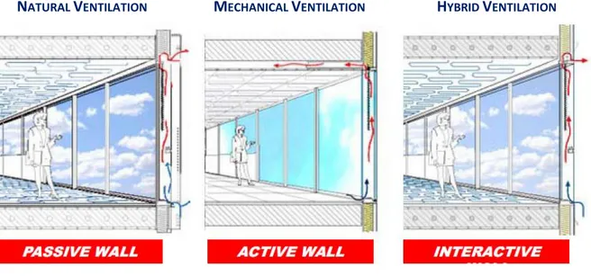
In the construction of transparent building envelopes, next to the structural and building-physics solutions, the concept for ventilating the building interior plays a decisive role. The main advantage is the dynamic insulation due to ventilation, that is in the air cavity between the two glass panes. The width of the cavity can vary as a function of the applied concept between 200 mm to more than 2 m [3]. The width influences the way the façade is maintained. The fundamental distinction between such ventilated façades depends on to the fact that the air inside the cavity is moves by natural forces (passive wall) or mechanical
20
(active wall, fan supported) [75]. There is also a hybrid operationing (interactive wall), which integrates both types of ventilation and allows to take advantage of natural ventilation without the use of mechanical equipment [57, 74], in order to optimize the energy efficiency of the system (Fig. 6). Multi layered glass façades offer many indirect advantages as well, particularly the twin-face façade, which allows natural ventilation in an environment with high winds, such as high-rise buildings. This type, the most popular in Europe, enables users to control their working environment while helping to eliminate "sick-building syndrome," which can result from an over-reliance on air-conditioning [12]. In winter, the glass layers enhance the heat-insulating functions of the facade owing to the comparatively higher surface temperatures of the inner surface of the facade. Moreover, according to studies by Drees & Sommer, environmental engineers in Stuttgart, two-layer facades improve sound insulation properties by 5 to 30 decibels, depending on the layout of the floors [2].
NATURAL VENTILATION MECHANICAL VENTILATION HYBRID VENTILATION
Fig. 6 Multi-layered and ventilated facades (courtesy of Permasteelisa Group).
The concept of multi-layered glass façades is quite complicated and its use and function affects different parameters of the building that often may interact with each other (daylight, natural ventilation, indoor air quality, acoustics, thermal and visual comfort, energy use, environmental profile, etc.) [2]. A successful application addresses this type of façade not as an isolated subsystem of a building, but as an integral part of the whole building, i.e. its construction, its technical equipment, and the overall energy balance [75].
21
2.4 C
LASSIFICATION
C
RITERIA BASED ON
T
ECHNOLOGY
The increased request of transparency in architectural envelops has led to rapid development in glass connections over the last 40 years. Transparent envelopes can be classified according to the type of glass used for the panel (annealed, toughened, insulated units, coated, tinted, laminated, etc. etc.) or according to the structural role of the glazing panels, that can play a primary or a secondary role in the functioning of the façade.
There are two main classes of connections for glass, namely framed glazing connections (linear supports) and frameless glazing connections (point supports). Framed systems include stick, veneer, unitised and panellised assemblies, in which the panels, opaque or transparent, are fully supported by the structure of the building and are applied externally to it by secondary elements.
In the second case, the glass panels themselves constitute the supporting structure of the façade, collaborate with each other and with the other structural elements (i.e. cross-bracing structures) to face loads such as dead and live loads, snow loads, wind loads and other horizontal actions, thermal stresses.
The classification of different glass curtain walling types can vary but the following terms are commonly used:
22
C) STRUCTURAL SEALANT GLAZING D) POINT SUPPORTED STRUCTURAL GLAZING
Images: Courtesy of CWCT (University of Bath).
2.5 S
TICK AND VENEER SYSTEMS
Stick-built glass façades are a curtain wall construction where much of the fabrication and assembly takes place in the construction site. Mullions of extruded aluminium may be prefabricated, but are delivered as unassembled “sticks” to the building site. The mullions are then installed onto the building face to create a frame for the glass, which is installed subsequently. Horizontal and vertical framing members (mullions or “sticks”) are normally extruded aluminium protected by anodising or powder coating, but may be cold-rolled steel (for greater fire resistance) or aluminium clad with PVC-U. Members are cut to length and machined in the factory prior to assembly on site as a kit
of parts: vertical mullions, which are fixed to the floor slab, are erected first followed by horizontal transoms, which are fixed in-between mullions (Fig. 7).
Mullions are typically spaced between 1.0 and 1.8m centres. Into the framework are fitted infill units, which may comprise a mixture of fixed and opening glazing and insulated panels (which may have metal, glass or stone facings). These units are typically sealed with gaskets and retained with a pressure plate, screw-fixed every
23
used for some stick systems. The pressure plate is generally hidden with a snap-on cover cap or overlapping gaskets. The screw fixings can be exposed by removing the cover, which is typically produced in six metre lengths for vertical framing elements. Fixings must be secured to the correct torque to retain the glazing/infill panels and to ensure proper compression of the gaskets for weather sealing.
Stick curtain walling is very common and versatile and can be used for anything from “glass towers” tens of storeys high to single storey shop fronts. Because of the number of joints in stick curtain walling it is generally very good at accommodating variabilities and movement in the building frame. It is also suitable for irregular shaped buildings. Assembly is slow compared with pre-assembled systems, and performance (i.e. weathertightness) depends on installers who are familiar with the assembly and sealing procedures for the particular system.
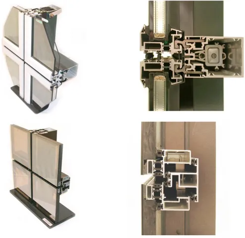
Many manufacturers and systems suppliers produce standard stick systems (Fig. 8). Insulated panels, usually designed for the project, may be faced with anything from aluminium or steel sheet, to glass or expensive stone composites. Some companies produce project-specific bespoke systems, either designing frame profiles from scratch for each job, or using standard details for some parts of the frame and simply altering some small aspect to give the appropriate structural properties or appearance. The type, complexity and budget of the project will normally determine whether a standard (i.e. “off-the-shelf”) or bespoke curtain wall is used.
24
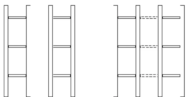
Fig. 8 Different Standard Stick Systems, frame and section profiles. Stick system curtain walling may be erected in one of three sequences: Mullions installed then transoms.
Mullions and transoms installed sequentially.
25
The term veneer system (Fig. 9 a and b) is useful in describing a variant of the stick system. With conventional curtain walls, the sticks must span between floor slabs. Structure systems used with structural glass façades, particularly the simple truss system, may incorporate a high tolerance flat face to provide continuous support to the glazing system. A veneer glazing system is essentially a stick-built curtain wall system designed for continuous support and representing a higher level of system integration with resulting efficiencies. Variations can include 4-sided capture, 2-sided capture, structurally glazed and unitized systems. The aluminium stick that is used in such an application requires no spanning capacity, since the supporting structure does all the spanning work. The glass system can thus be reduced to the minimum required to facilitate attachment of the glass to the structure.
Fig. 9 a and b. Veneer systems.
Truss systems can be designed with an outer chord of square or rectangular tubing, and may include transom components of similar material, presenting a uniform flat grid installed to high tolerances. Such a system can provide continuous support to the simplest and most minimal off-the-shelf glazing system, thus combining relatively high transparency with
26
excellent economy and eliminating unnecessary redundancy between the structure and the glass panels.
2.6 U
NITISED AND
P
ANELLISED
S
YSTEM
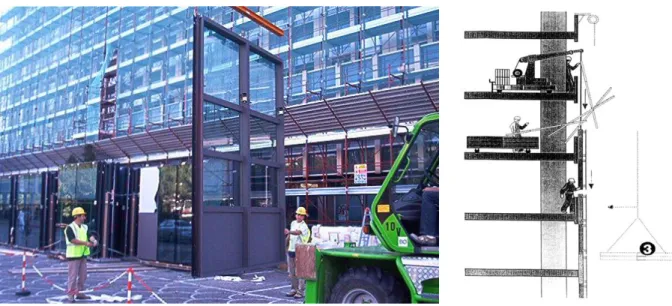
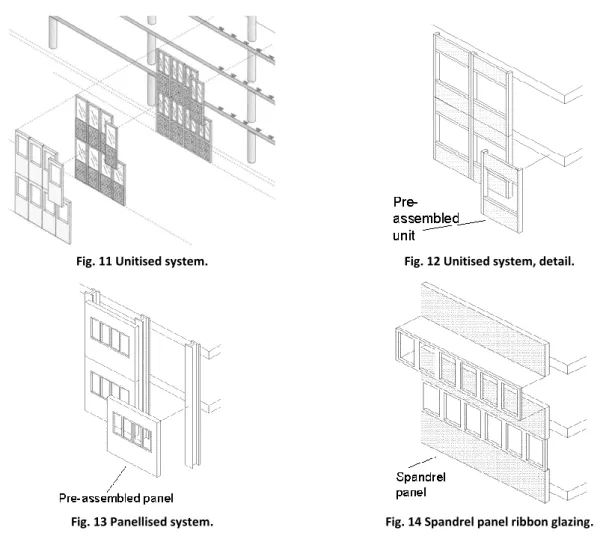
Unitised systems (Fig. 10 a and b) comprise narrow, storey-height units of steel or
aluminium framework, glazing and panels pre-assembled under controlled, factory conditions. Mechanical handling is required to position, align and fix units onto pre-positioned brackets attached to the concrete floor slab or the structural frame. Unitised systems are more complex in terms of framing system, have higher direct costs and are less common than stick systems. The smaller number of site-sealed joints in unitised curtain walling simplifies and hastens enclosure of the building, requires fewer site staff and can make such systems cost effective (Fig. 11, 12).
Fig. 10 a and b. Installation of a unitised assembly.
If construction joints interlock consideration must be given to how damaged units could be removed and replaced. The reduced number of site-made joints compared with stick systems, generally leads to a reduction in air and water leakage resulting from poor installation. Some authors do not differentiate between unitised and panellised systems, but panellised construction may have significant internal steel structure to support the extra weight, or may consist of precast concrete panels with openings for windows.
27
Panellised curtain walling (Fig. 13) comprises large prefabricated panels of bay width
and storey height, which connect back to the primary structural columns or to the floor slabs close to the primary structure. Fixing the panels close to the columns reduces problems due to deflection of the slab at mid span, which affect stick and unitised systems.
Fig. 11 Unitised system. Fig. 12 Unitised system, detail.
Fig. 13 Panellised system. Fig. 14 Spandrel panel ribbon glazing.
Spandrel panel ribbon glazing (Fig. 14) is a long or continuous run of vision units fixed
between spandrel panels supported by vertical columns or the floor slabs. Glazed areas may comprise several standard windows fixed together on site by joining mullions or pre-glazed, bay width, factory-assembled frames, or individual framing sections and glass infill panels which are site assembled. Ribbon glazing is often used in conjunction with spandrel panels, that is, horizontally spanning prefabricated or precast concrete units. It may also be used with spandrels comprising upstand walls faced with rainscreen panels. Ribbon glazing/spandrel panel construction generally results in buildings having a horizontal banded or strip appearance.
28
Units or panels may be of precast concrete or comprise a structural steel framework, which can be used to support most cladding materials (i.e. stone, metal and masonry). Aluminium or galvanised steel skins are generally fixed to the frame with insulation in the cavity. The wall construction is then completed by a plasterboard lining and external cladding. Joints may comprise gasketted interlocking extrusions, gaskets between separate extrusions or wet applied sealant. The advantages of using such systems is the high utilisation of prefabrication, which allows better quality control and rapid installation with the minimum number of site-sealed joints. However, a large number of identical panels is required in order to be cost effective. Panellised systems are less common and more expensive than unitised construction. The size and weight of panels is limited by the practicalities of manufacture, handling, storage, transport and erection [84].
2.7 S
TRUCTURAL
S
EALANT
G
LAZING
(SSG)
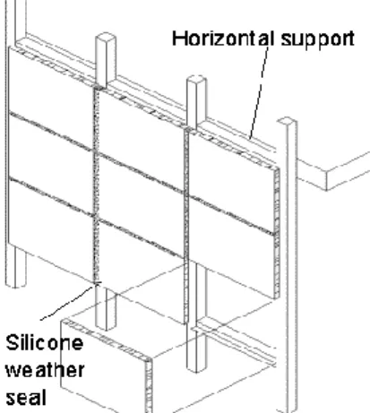
Structural sealant glazing (Fig. 15) is a form of glazing that uses a structural sealant (usually silicone adhesives) to attach glass, metal or other panel material to the structure of a building Glazing panels are glued externally to the steel structure by an adhesive, mainly by structural silicone. In addition, some mechanical anchorage can be provided. This kind of facade, also known as VEC (Vitrage Extérieur Collé), offers a continuity of the external glass surface, only interrupted only by the lines drawn by the thin thickness of the joints (Fig. 18).
Wind load and other impact loads on the façade are transferred from the glass through the structural silicone sealant to the structure of the building [65]. The sealant must maintain adhesive and cohesive integrity as the façade is also subjected to thermal stresses: external joints are weathersealed with a wet-applied sealant or a gasket. Structural glazing projects differ in building design, environment and customer requirements, but structural sealant glazing can be applied to stick curtain wall systems and windows, particularly ribbon glazing. However it can also be used in unitised and panellised systems.
The concept of structural glazing has been developed in the laboratories of American sealing material manufacturers and was subjected to intensive testing during the ‘60s and
29
‘70s. Structural sealant glazing has been used in the USA for around 30 years where it was initially site applied directly to the steel framing. However, this is no longer acceptable due to difficulties of application and replacement and all structural silicone joints are now made in a factory [86]. Glass replacement/resealing must be undertaken in a controlled environment using the correct materials. All elements used in the construction must be compatible with the silicone sealant.
Fig. 15 Structural sealant glazing.
Fig. 16 2-sided Structural Glazing. Fig. 17 4-sided Structural Glazing. Fig. 18 Structural silicone glazing (VEC)
installation.
There are many different types of structural glazing systems available. Two of the more common types of systems are 2-sided SG and 4-sided SG. Structural sealant glazing systems can have sealant on two opposite sides (Fig. 16): the other two sides of the glass are either mechanically supported or are not structurally supported by a frame. The most common and usually cost efficient type of structural glazing is 4-sided SG systems (Fig. 17). Glass is
30
supported on all four edges of the glass with structural sealant and such systems are typically fabricated in a production facility and erected at a jobsite.
A structural glazing joint must be properly designed for the sealant to function as intended: typical details are in Fig. 19 and 20. The structural bite is the minimum width or contact surface of the silicone sealant on both the glass panel and the frame. The glass panel dimensions, design dead loads, impact loads, windload and thermal dilatation stresses must be considered in the determination of the structural bite dimension. The thickness (often referred as glueline thickness) is the distance from the panel to the frame. Proper thickness facilitates the installation of the sealant and allows reduced sealant stress from differential thermal movement between the glass panel and the frame.
Fig. 19 Typical structural mullion detail. Fig. 20 Typical structural transom detail.
The tightness of the system may be ensured by the presence of small horizontal projections that help to hold the weight of glass panes, while the shear forces and those produced by pressure and depression of the wind are entrusted to the sealant. The presence of this element allows to compensate for the possible creep of the structural silicone along the perimeter of the slab. Structural sealant glazing can be used to create a building exterior aspect that is free from protrusions, but the framing system will be visible at night when backlit. Any of the previous types of curtain walling and ribbon glazing could incorporate structural silicone glazed elements.
However, this technology has considerable limitations, especially related to safety: the uncertain structural behaviour imposes the adoption of high safety coefficients (from 3 to 6)
31
and the use of additional mechanical anchorage, consisting of small protrusions that provide support for slabs and remain almost invisible at a distance of 3-5 m [86].
2.8 P
OINT SUPPORTED
S
TRUCTURAL
G
LAZING
The further evolution of structural sealant glazing systems is the point supported structural façade, also known as VEA (Vitrage Extérieur Agrafé), in which glass panes are bound to the main structure through separate connecting elements (brackets and/or cables) instead of a frame. This is a system of frameless glazing wherein glass units or panels are bolted together due to an independent support structure, or to glass fins, and the joints in between them sealed with structural joints. Glass sheets are fastened to the support structure by point-fixed devices in correspondence of the four corners; different technologies are available for the types of fixings and the design of the joints, developed by different manufacturers (Saint Gobain, Pilkington etc.).
Recent developments in the design of transparent building envelopes aims at minimize the “visible” structure. Such systems overcome the restrictions of conventional frames to use mechanical fixings with toughened safety glass, and combine strength and visible lightness to provide high performance façade systems [86].
Frameless systems utilize glass panes that are fixed to a structural system at discrete points, usually near the corners of the glass panel (point-fixed). The glass is directly supported without the use of perimeter framing elements. The glass used in point-fixed applications is typically heat-treated. Structural glass wall design can be complex and depends on design loads, seismic movements, support structure and glass support method. Nevertheless some typical glass point supported systems can be described. Three different main types can be distinguished:
Ground Based Assemblies. Conventional toughened glass entrance systems are the basic form of ground based assemblies, where the glass dead load is supported by the floor. They can be designed with or without doors and are normally a maximum of two tiers and 6 metres high, requiring lateral support from glass fins or a steel structure.
32
Fully Fixed Assemblies. For these systems the individual panels are normally fixed directly to the support structure, which can be steel, masonry or any other suitable structure. Normally the panes are fixed at the corners and the structure is designed to accommodate building movement at the perimeter.
Suspended Assemblies. The suspended assembly is the most versatile structural glass system and can be hung up to 20 metres in height. The adjustable suspension system in conjunction with perimeter channels permits the system to move independently of the building structure. This compensates for construction dimensional variations and overcomes problems associated with building movement, vibration and seismic loads. The glass facade is hung from the building structure like a curtain. The top tier panels are connected to the structure by adjustable hanger brackets and subsequent lower panels are connected by special fittings at their corners. The facade is located into channels at the perimeter and all glass joints and channels are sealed with silicone sealant. The hanging assembly is normally stabilised against wind load by glass fins located and fixed to the support structure with fittings at the joints.
Bolted structural glass assemblies (Fig. 21) have evolved from the systems of the 1960’s
and 70’s through the introduction of Pilkington’s Planar system in 1981 and RFR’s La Villette ball-joint system. The bolted version is the most popular glass system and frequently the most expensive for application with structural glass façades. The glass panel requires perforations to accommodate specialized bolting hardware.
The bolted glass assembly system is a technique for installing glass using articulated stainless steel bolts or brackets and supported by a secondary structure (Fig. 22). The bolts are designed to absorb:
the weight of the glazing,
the differential movements between the glass and structure, wind and/or snow loading.
The system is designed for walls, roofs and canopies, both vertical and inclined. The glass panes can be monolithic single-glazing, laminated single glazing or double-glazing (Fig. 23);
33
they are normally rectangular in shape and can be flat or curved in form. The bolted glass assembly system requires finished glass products of the highest quality in terms of edge-work, drilling, toughening and heat soak testing. Each production stage must be quality controlled to the highest standard. Throughout the manufacturing process, particular attention is paid to two aspects: dimensional accuracy and the toughening and heat-soak testing of the glass.
The glass elements must be selected in accordance with regulations governing the safety of building users and the specifications of bolted glass assemblies:
in the event of breakage, limiting of the risk of injury to persons guarding to protect people from falling
safety of building users and operatives during cleaning and maintenance operations
Fig. 21 Bolted glass assembly.
Fig. 22 Load bearing.
Fig. 23 Types of glazing.
For this type of application, the most stringent manufacturing requirements for glass apply to edgework and drilling, and to toughening and heat soak testing (Fig. 24). All
34
edgework must be completed before the toughening and heat soak test stages. The glass cannot be altered in any way after this treatment. The minimum distance (d) between the edge of a hole and the edge of the glass must be twice the thickness (t) of the glass. (d) minimum is usually 60 mm, but this parameter varies depending on the application (Fig. 25).
Fig. 24 Hole shapes. Fig. 25 Hole dimensioning.
The glass must be designed to accommodate bending loads and deflections, resulting from the fixing technology. An insulated-laminated glass panel as required for overhead applications will require the fabrication of 12 holes per panel, which can represent a cost constraint on some projects [84]. Two processes for mechanically reinforcing the glass are currently used: the first process consists of toughening followed by heat soak testing (fine fragmentation). This produces a safety glass in accordance with EN 12150. The alternative process is heat-strengthening: fragmentation similar to that of annealed glass. This product is not considered to be a safety product as classified in EN 12150 [86].
Lateral support is provided by toughened and/or laminated glass fins or by connections off the main building structure and/or secondary steel support structures. Glass fins can be cantilevered, full height simply supported or full height propped cantilever. They can be spliced to create longer lengths, while depth and thickness will depend on the design loads.
Steel structure behind the point fixed glass façades can range from simple pipe columns to extremely complicated truss systems: a multitude of discreet or prominent secondary structures can be designed, which support the glazing through special brackets, while the joints between adjacent panes/glass units are weathersealed on site with wet-applied sealant.
The weather seal in most structural glass façade systems is provided by a field applied butt-glazed silicone joint. This technique provides a reliable and durable weather seal if simple procedures are followed during installation. An advantage of this sealing strategy is
35
that any leaks, usually caused by installation errors, are easily detected and repaired. The joint design is critical, and is largely a function of the glass makeup and thickness. Compatibility between the field-applied silicone and the interlayer, if using laminated glass, or the edge seal in the case of an IGU, must be confirmed with the silicone material provider. The provider should also be consulted about the joint design. Craftsmanship is critical for the field application of the sealant to assure a visually satisfactory result.
Cast stainless steel spider fittings are most commonly used to tie the glass to the supporting structure. The standard connectors (Fig. 26 a, b, c, d, e, f) connect the glass fittings to the backup structure and are normally use 316° stainless steel. Sliding spider casting with spring loaded arms is installed to resist to high horizontal loading.
Fig. 26 a, b, c (above ) c, d e f (below). 4 and 2 point stainless steel connectors.
Point-fixed clamped systems (Fig. 27 and 28) accomplish the point fixing without the requirement for perforations in the glass. In the case of a spider type fitting, the spider is rotated 45° from the bolted position so that its arms align with the glass seams. A thin blade penetrates through the seam between adjacent pieces of glass. An exterior plate attaches to the blade and clamps the glass in place. The bolted systems present an uninterrupted glass surface, while the clamped systems expose the small exterior clamp plate. Some façade designers prefer the exposed hardware aesthetic.
36
Fig. 27 Detail of a clamped system. Fig. 28 Point-fixed clamp assembly.
High glass walls are usually suspended to accommodate the building movements, in particular for earthquakes. The suspended assembly (Fig. 29) consists of monolithic or double glazed insulated glass units are suspended at
the top edge and spider fitting point links fix the glass panels all the way down to the floor. The glass is fixed together (with corner, rectangular, patch plates) and the whole assembly is then either suspended from the top or stacked from the ground and wet-sealed on site. Suspended glazing systems utilise the minimum amount of framing for a given glass area. There are different kind of stiffeners in order to resist the horizontal loads (wind pressure, seismic loads).
GLASS MULLION SYSTEMS. The glass fin-supported façade is one of the earliest form of
structural glass system and it uses glass fins as a mean of support for maximum transparency to brace the assembly: glass panels are stiffened along their vertical edges by a perpendicular glass mullion in thick tempered glass (Fig. 30).
The façade is suspended from the structure above with the glass panels fastened to the mullions by the fittings. This means the combined weight of both the panels and the mullions is carried by the connection at the head of each fin (Fig. 31). This system is preferable used in areas of high seismic activity. Glass fin-supported facades still
37
represent one of the most transparent forms of structural glass façade and an economical solution (especially at lower spans).
Fig. 30 Glass fins. Fig. 31 Loads.
TENSION STRUCTURES. Various forms of cable-stayed backup systems can be used to support
a glass suspended façade. Such assemblies can be suspended by perpendicular and/or horizontal tension truss unit. In some designs the light truss stabilises the wall and transfers wind loading, while the weight of the glass is transferred through the corner plates and suspension system. In all instances, the capabilities and loading of the glass must be used as the basis of the design for the backup structural system. Three forms of tension assisted glass wall systems can be identified and they vary from simple steel tubular trusses all the way to complete rod or cable tension structures. Various combinations of these basis systems can be created, as shown in the table below:
CABLE TRUSS
Lightweight and maximum transparency Generates high tensile loads into
boundary structure
Requires increased support stiffness Upper range of pricing
38
BOW STRING TRUSS
No tension forces are transferred into boundary structure
Erects quickly
Middle range of transparency Medium range of pricing
PRIMARY TRUSS WITH SECONDARY RIGGING SYSTEM
Conventional truss fabrication Rigid assembly
Less transparency
Most economical range of pricing
(courtesy of Pilkington)
Truss systems employ a planar truss design, often in a hierarchical system that may combine other element types including tension components. Truss designs vary widely, with an emphasis on fine detailing and craftsmanship.
GRID SHELLS.Grid shell structural systems are another means to minimize the visual mass
of structure. Configurations can be vaulted, domed and double-curved (Fig. 32). Systems can be welded, bolt-up, or some combination of each. Grid shell structures with integrated cable bracing can produce a highly efficient structure with a refined aesthetic. Cable pre-stress is required on such systems. Grid shells can be used in vertical and overhead applications, as well as to form complete building enclosures. Grid systems can be supported also by timber structures (Fig. 33).
39
Fig. 32 Grid shell with stainless steel support structure. Fig. 33 Grid shell with timber support structure.
CABLE NET STRUCTURES.Cable nets represent the most effective way in minimalist structural
systems and can provide optimum transparency when the effect of a sheer glass membrane is desired. The glass is supported by a net geometry of pre-tensioned cables. Planar two-way cable systems support and stabilize glass façades through the resistance to deformation of the two-way pretensioned net. Gravitational loads from the glass elements are carried through the attachment nodes to the vertical cables and up to a transfer structure in the base building above. Lateral deformations due to wind and seismic loadings are resisted by the tendency of each horizontal and vertical cable to return to its straight line configuration between supports. Large pre-stress loads in the net structures require the early involvement of the façade design team with the structural engineer. A clamping component locks the cables together at their vertices and fixes the glass to the net: the connection consist of point-fixed clamp assembly (Fig. 34 a, b) or 2 and 4 (Fig. 35 a, b) point connectors.
Fig. 34 a, b. Cable net clamped system (courtesy of Sentech).
Fig. 35 a, b. Cable net spider system (courtesy of Sentech).