DIPARTIMENTO DI INGEGNERIA CIVILE
Dottorato di Ricerca in Ingegneria delle Strutture e del
Recupero Edilizio ed Urbano
IX Ciclo N.S. (2007-2010)
ANALISI TEORICO-SPERIMENTALE
DI COLLEGAMENTI DISSIPATIVI A PARZIALE
RIPRISTINO DI RESISTENZA IN STRUTTURE
INTELAIATE IN ACCIAIO
Massimo Latour
Il Tutor
Il Coordinatore
Prof. Gianvittorio Rizzano Prof. Ciro Faella
Il Co-Tutor
Concludere questa tesi significa per prima cosa giungere al termine di questi tre anni sicuramente belli, anche se non sempre sereni, di esperienza di dottorato. Il rammarico con cui si lascia alle spalle quanto vissuto fin qui, per continuare la propria vita lavorativa verso nuovi obiettivi, è enorme.
Il ringraziamento più grande voglio rivolgerlo alle persone con cui mi sono ritrovato ogni giorno a condividere tutto (dal laboratorio ai pranzi frugali). Un particolare ricordo va a Riccardo e Fabio, colleghi del gruppo di ricerca, con cui ho trascorso gran parte di questo periodo e senza i quali non avrei mai conseguito questo obiettivo. Mi rende felice e per questo mi fa piacere menzionare Saverio e Francesco, compagni di stanza, ma prima di tutto amici. E’ doveroso ringraziare, con grande stima e riconoscenza, il Prof. Gianvittorio Rizzano e il Prof. Vincenzo Piluso, che hanno rappresentato per me un punto di riferimento, ma anche un meraviglioso esempio di come si possa essere persone prima ancora che valenti accademici.
In questo momento non posso non pensare a mia madre e mio padre che, ormai, non sopportano più di vedermi curvo su libri di cui non riescono a comprendere nemmeno il significato del titolo. Infine Manuela, presenza costante cui devo molto di quanto sono riuscito a costruire in questi ultimi tre anni e senza la quale forse non ce l’avrei fatta ad essere qui a mettere questo punto.
Knowledge without follow-through is worse than no knowledge
(Charles Bukowski)
1. INTRODUCTION
1.1 SCOPE OF THE STUDY
1
2. SEISMIC BEHAVIOR OF MOMENT RESISTING FRAMES
2.1 THE STRUCTURAL TYPOLOGY
5
2.1.1 MRFS SPATIAL DISTRIBUTION
10
2.1.2 THE CONNECTION TYPOLOGIES
15
2.1.3 DUCTILITY CLASS
21
2.1.4 STIFFNESS AND STRENGTH OF JOINTS
28
2.2 FRAMES AND JOINTS CLASSIFICATION
34
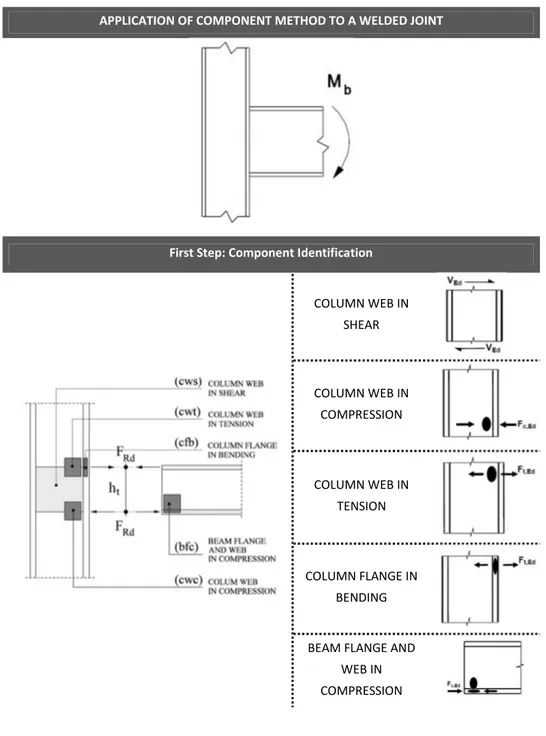
2.3 THE COMPONENT METHOD
42
2.4 THE ROLE OF CONNECTIONS ON THE OVERALL STRUCTURAL
BEHAVIOR
53
3. CYCLIC BEHAVIOR OF BEAM-TO-COLUMN JOINTS: EXPERIMENTAL
CAMPAIGN
3.1 INTRODUCTION
73
3.2 DESCRIPTION OF THE TEST SETUP
78
3.3 DESIGN OF THE SPECIMENS
93
3.3.1 DESIGN OF SPECIMEN EEP-CYC 01
93
3.3.2 DESIGN OF SPECIMEN EEP-CYC 02
107
3.3.3 DESIGN OF SPECIMEN EEP-DB-CYC 03
112
3.3.4 DESIGN OF SPECIMEN TS-CYC 04
118
3.4 DESCRIPTION OF THE EXPERIMENTAL TESTS
121
3.4.1 DESCRIPTION OF TEST EEP-CYC 01
121
3.4.2 DESCRIPTION OF TEST EEP-CYC 02
127
3.4.3 DESCRIPTION OF TEST EEP-DB-CYC 03
136
3.4.4 DESCRIPTION OF TEST TS-CYC 04
141
3.4.5 GEOMETRICAL AND MECHANICAL PROPERTIES OF THE
SPECIMENS
148
3.4.6 COMPARISON AMONG THE TESTS
153
3.6 REFERENCES
157
4. CYCLIC BEHAVIOR OF BEAM-TO-COLUMN JOINTS: MECHANICAL
MODELING
4.2 CYCLIC MODELING OF THE JOINT COMPONENTS: LITERATURE
REVIEW
166
4.2.1 MODELING OF THE PANEL ZONE IN SHEAR
166
4.2.1.1 FIELDING AND HUANG MONOTONIC MODEL (1971)
169
4.2.1.2 KRAWINKLER MONOTONIC MODEL (1971)
174
4.2.1.3 WANG MONOTONIC MODEL (1985)
178
4.2.1.4 FIELDING AND WANG MODIFIED MONOTONIC MODEL
(1996)
181
4.2.1.5 KIM & ENGELHARDT MONOTONIC MODEL (2002)
183
4.2.1.6 KIM & ENGELHARDT CYCLIC MODEL (2002)
190
4.2.2 MODELING OF COLUMN WEB PANELS UNDER TENSION AND
COMPRESSION
201
4.2.3 MODELING OF THE T-STUB IN TENSION
212
4.3 ASSEMBLY AND ACCURACY OF THE MODEL
218
4.4 REFERENCES
239
5. APPLICATION OF DISSIPATIVE DEVICES TO BEAM-TO-COLUMN
JOINTS
5.1 ENERGETIC APPROACHES: MAIN FEATURES
243
5.1.1 PASSIVE ENERGY DISSIPATING SYSTEM
255
5.1.2 BASIC RESPONSE OF STRUCTURES EQUIPPED WITH HYSTERETIC
5.1.3 METALLIC AND FRICTION DAMPERS
267
5.1.3.1 METALLIC FLEXURAL DISSIPATING DEVICES
273
5.1.3.2 METALLIC SHEAR DISSIPATING DEVICES
278
5.1.3.3 FRICTION DISSIPATING DEVICES
280
5.2 DEVELOPMENT OF DISSIPATIVE T-STUBS
283
5.2.1 MECHANICAL MODELING
286
5.2.1.1 RECTANGULAR T-STUBS – PILUSO ET AL. MODEL (1997) 286
5.2.1.2 DISSIPATIVE T-STUBS – PROPOSED MODEL
310
5.2.2 EXPERIMENTAL BEHAVIOR UNDER CYCLIC LOADS
329
5.2.2.1 MONOTONIC TESTS - T-STUBS ON RIGID SUPPORT
336
5.2.2.2 MONOTONIC TESTS - COUPLED T-STUBS
343
5.2.2.3 CYCLIC TESTS – T-STUBS ON RIGID SUPPORT
348
5.2.2.4 CYCLIC TESTS – COUPLED T-STUBS
354
5.3 APPLICATION OF DISSIPATIVE T-STUBS TO DOUBLE SPLIT TEE
JOINTS
358
5.3.1 THE ROLE OF MOMENT-SHEAR INTERACTION
366
5.3.1.1 EFFECT OF MOMENT-SHEAR INTERACTION ON THE
VALUE OF THE PLASTIC MOMENT
366
5.3.1.2 OPTIMUM SHAPE OF DISSIPATIVE T-STUBS
381
5.3.2 EXPERIMENTAL TESTS ON DISSIPATIVE T-STUB JOINTS
391
5.3.2.1 DESIGN OF TESTED SPECIMENS
392
5.3.2.2 DESCRIPTION OF TEST TSJ-XS-CYC 06
399
5.3.2.3 DESCRIPTION OF TEST TSJ-XS-CYC 07
406
5.3.2.4 COMPARISON BETWEEN DISSIPATIVE AND CLASSICAL
JOINTS
412
Fig. 2.1 – Steel Moment Resisting Frames in U.S.A. 5
Fig. 2.2 - Structural Typologies of CBF and EBF 7
Fig. 2.3 - Buildings Erected applying the “Column Tree” Technique 8 Fig. 2.4 – Classification of Moment Resisting Frames 9
Fig. 2.5 – Spatial Distribution of Space Frames 10
Fig. 2.6 – Spatial Distribution of Perimeter Frames 11 Fig. 2.7 – Spatial Distribution of Perimeter Frames with only few rigid bays 12
Fig. 2.8 – Spatial Distribution of Planar Frames 13
Fig. 2.9 – Spatial Distribution of Hybrid Systems 14
Fig. 2.10 – Rivets and High Strength Bolts 16
Fig. 2.11 - Examples of riveted structures 17
Fig. 2.12 – On the left: FCAW welding technique; On the right: SMAW
welding technique 18
Fig. 2.13 – Failure of beam-to-column fillet welded connection
(Kobe Earthquake) 20
Fig. 2.14 – Structural Joints Configuration (CEN, 2005) 28 Fig. 2.15 – Distinction between Connection and Panel zone 30 Fig. 2.16 – Pinned, Continuous and Semi-continuous joints 31 Fig. 2.17 – Modeling of a welded joint with the component method 46 Fig. 2.18 – Simplified model adopted by (Piluso et al., 1994) 59 Fig. 2.19 – Influence of non-dimensional stiffness on the period of vibration 61 Fig. 2.20 – Influence of non-dimensional stiffness on stability coefficient 62 Fig. 2.21 – Results of the parametric analysis (Aribert & Grecea, 2000) 64 Fig. 2.22 – Proposal of behavioral factor for semi-continuous MRFs 65 Fig. 3.1 – Constraining devices used in the experimental campaign 79
Fig. 3.2 – MTS Hydraulic testing machine 81 Fig. 3.3 – Universal testing machine SCHENCK Hydropuls S56 82
Fig. 3.4 – Scheme and picture of an LVDT 83
Fig. 3.5 – Scheme and picture of an LVDT 84
Fig. 3.6 – Scheme and picture of an inclinometer 85
Fig. 3.7 – Scheme of a Strain Gauge 85
Fig. 3.8 – Actions in a frame due to seismic loads 86
Fig. 3.9 – Scheme reproduced in laboratory 86
Fig. 3.10 – AISC loading history for beam-to-column joints 87
Fig. 3.11 – Position of the instruments 89
Fig. 3.12 – Setup of the measurement devices 90
Fig. 3.13 – Experimental Setup 92
Fig. 3.14 – Definition of the equivalent shear acting in the panel zone 94 Fig. 3.15 –Rendering and Geometry of joint EEP – CYC 01 99 Fig. 3.16 – Simplified model considered in the design of end-plate
(CEN, 2005) 100
Fig. 3.17 – Influence of coefficient on the collapse mechanism 103 Fig. 3.18 – Geometry and rendering of specimen EEP-CYC 02 112
Fig. 3.19 – Definition of RBS parameters 113
Fig. 3.20 – Typical scheme of beam with RBS 114
Fig. 3.21 – Scheme of the actions transferred by the RBS to the column 117 Fig. 3.22 – Rendering and Geometry of test TS-CYC 04 120
Fig. 3.23 – Test EEP-CYC 01 121
Fig. 3.24 – Measurement devices EEP-CYC 01 121
Fig. 3.25 – Measurement devices EEP-CYC 01 122
Fig. 3.26 – Failure of EEP-CYC 01 speciment due to brittle collapse of beam
flange to end-plate welds 123
Fig. 3.28 – Hysteretic response of end plate equivalent T-stubs 125 Fig. 3.29 – Cyclic response of column web in shear 126 Fig. 3.30 – Cyclic response of column web under alternate tension and
compression 126
Fig. 3.31 – Energy dissipation of specimen EEP-CY 01 127
Fig. 3.32 – Test EEP-CYC 02 128
Fig. 3.33 – Measurement devices EEP-CYC 02 129
Fig. 3.34 – EEP-CYC 02 Moment-Rotation Curve 130
Fig. 3.35 – Component Hysteretic curves for specimen EEP-CYC 02 132 Fig. 3.36 – Formation of the crack in the end-plate 133
Fig. 3.37 – Failure of the end-plate 134
Fig. 3.38 – Energy dissipation of specimen EEP-CYC 02 135
Fig. 3.39 – Setup of test EEP-DB-CYC 03 136
Fig. 3.40 – Measurement instruments used to monitor the joint components 137 Fig. 3.41 – Straing Gauge used to monitor deformations of the Dog-Bone 137 Fig. 3.42 – Energy Dissipation of specimen EEP-DB-CYC 03 138
Fig. 3.43 – Flange and web buckling 139
Fig. 3.44 – Flange and web buckling 140
Fig. 3.45 – Test TS-CYC 04 141
Fig. 3.46 – Measurement devices 142
Fig. 3.47 – TS-CYC 04 Moment-Rotation Curve 143
Fig. 3.48 – Formation of the plastic hinges in correspondence of bolts and
plate-web tie 144
Fig. 3.49 – Plasticization of the Tee elements 145
Fig. 3.50 – Development of the plastic hinges and failure of the Tee
elements 146
Fig. 3.51 – Components hysteretic curves for specimen TS-CYC 04 147 Fig. 3.52 – Energy Dissipation of TS-CYC 04 joint 148
Fig. 3.53 – Experimental results of a coupon tensile test 149 Fig. 3.54 – Comparison between the actual and the engineering
stress-strain relationship 150
Fig. 3.55 – Notation for the definition of the geometrical properties 151 Fig. 3.56 - Energy dissipation capacities of the tested joints 154 Fig. 3.57 – Comparison among the cyclic curves of the testes specimens 155 Fig. 4.1 – Mechanical model for bolted connections 164
Fig. 4.2 – Modeling of an internal welded joint 168
Fig. 4.3 – (Mulas, 2004) FEM model 169
Fig. 4.4 – Bilinear model of Fielding and Huang 170
Fig. 4.5 – Post-elastic model of Fielding and Huang (1971) 172 Fig. 4.6 – Translational equilibrium (Fielding model) 172 Fig. 4.7 – Apllication of Fielding & Huang model 173
Fig. 4.8 – Tri-linear model of Krawinkler 174
Fig. 4.9 – Post-elastic model (Krawinkler,1971) 175
Fig. 4.10 – Krawinkler model in case of HEB 200 column and IPE 270 beam 177
Fig. 4.11 – Shear panel model (Wang, 1985) 178
Fig. 4.12 – Wang post-elastic model 179
Fig. 4.13 – Wang model 180
Fig. 4.14 – Comparison between Fielding and Wang models (Left) and
Improved Fielding and Wang models (Right) 182
Fig. 4.15 – Quadri-linear model of Kim & Engelhardt 183 Fig. 4.16 – Comparison among literature models in case of HEB 200-IPE 270
coupling 188
Fig. 4.17 – Comparison among literature models for FEM analysis tcf=27
mm 189
Fig. 4.18 – Comparison among literature models for FEM analysis tcf=36
Fig. 4.19 – Comparison among literature models for FEM analysis tcf=45
mm 190
Fig. 4.20 – Kinematic Hardening model 191
Fig. 4.21 – Application of Kinematic Hardening model to Krawinkler
specimen-A1 192
Fig. 4.22 – Cyclic steady state curve 193
Fig. 4.23 – Shear Panel cyclic curve 194
Fig. 4.24 – Dafalias-Popov model for Hysteresis Curve 196 Fig. 4.25 – Procedure for the translation of the bound line 197
Fig. 4.26 – Comparison with Krawinkler test A1 199
Fig. 4.27 – Comparison with Krawinkler test A2 200
Fig. 4.28 – Column web subjected to compression 201
Fig. 4.29 – Column web subjected to tension 202
Fig. 4.30 – Transitory phase 203
Fig. 4.31 – Stabilized response 204
Fig. 4.32 – Stabilized response after softening 205
Fig. 4.33 – Hardening factor 206
Fig. 4.34 – Softening factor 207
Fig. 4.35 – Relaxation factor 208
Fig. 4.36 – Cyclic curve at the i-th cycle for panels in tension and
compression 210
Fig. 4.37 – Hysteresis curve in Cofie model 211
Fig. 4.38 – Theoretical-experimental comparisons 212
Fig. 4.39 – Piluso et al. model 215
Fig. 4.40 – Geometry of EEP-CYC 01 specimen 220
Fig. 4.41 – Geometry of EEP-CYC 02 specimen 221
Fig. 4.42 – Geometry of TS-CYC 04 specimen 222
Fig. 4.44 – Geometry of J-1.3 specimen (Nogueiro et al., 2006) 224 Fig. 4.46 – Theoretical-Experimental comparison for specimen EEP-CYC 01 226 Fig. 4.47 – Theoretical-Experimental comparison for specimen J-1.3 226 Fig. 4.48 – Comparison of the energy dissipated for specimen EEP-CYC 01 227 Fig. 4.49 – Comparison of the energy dissipated for specimen J-1.3 227 Fig. 4.50 – Theoretical-Experimental comparison for specimen FW 229 Fig. 4.51 – Comparison of the energy dissipated for specimen FW 230 Fig. 4.52 – Theoretical-Experimental comparison for specimen EEP-CYC 02 231 Fig. 4.53 – Theoretical-Experimental comparison for specimen TS-CYC 04 231 Fig. 4.54 – Theoretical-Experimental comparison for specimen FPC/B 232 Fig. 4.55 – Comparison of the energy dissipated for specimen EEP-CYC 02 233 Fig. 4.56 – Comparison of the energy dissipated for specimen TS-CYC 04 233 Fig. 4.57 – Comparison of the energy dissipated for specimen FPC/B 234 Fig. 4.58 – Model performance - Peak Moment for Authors’ Tests 236 Fig. 4.59 – Model performance - Unloading Stiffness for Authors’ Tests 237 Fig. 4.60 – Model performance - Peak Moment for Literature Tests 237 Fig. 4.61 – Model performance - Unloading Stiffness for Literature Tests 238 Fig. 5.1 – Time variation of the energy dissipate by viscous damping of an
elastic (top) and inelastic system (bottom) 246
Fig. 5.2 – Rain flow analogy 247
Fig. 5.3 – Seismic Control Systems 250
Fig. 5.4 – Control Schemes 251
Fig. 5.5 – Tuned Mass Damper - Tuned Sloshing Damper – Tuned Liquid
Damper 254
Fig. 5.6 – Response of damped system subjected to harmonic forces 259 Fig. 5.7 – Deformation response factor for damped system (harmonic force) 261 Fig. 5.8 – Single-degree-of-freedom system incorporating hysteretic damper 262 Fig. 5.9 – Steady-state response amplitude of single-degree-of-freedom with
hysteretic damper under harmonic base excitation, kd/k = 0.55 265 Fig. 5.10 – Typical response of metals subjected to monotonic and cyclic
loads 268
Fig. 5.11 – Atomic arrangements corresponding to: a) edge dislocation; b)
screw dislocation 270
Fig. 5.12 – Cyclic response of ADAS devices 273
Fig. 5.13 – Curvatures developed for different plate geometry 274 Fig. 5.14 – Application of ADAS device to a three stories steel MRFs 275 Fig. 5.15 – Geometry and Response of T-ADAS devices 276 Fig. 5.16 – Geometry and Response of Honeycomb devices 277 Fig. 5.17 – Distribution of Shear Panels in MRFs (Nakashima, 1995) 278 Fig. 5.18 – Shear Damper proposed by (Cahis et al., 1997) 279 Fig. 5.19 – Shear Damper proposed by (Tsai) (Tsai & Wang, 1998) 280 Fig. 5.20 – T-stub Identification in case of Extended end plate Connections 286
Fig. 5.21 – Failure modes of bolted T-stubs 287
Fig. 5.22 – Adopted Notation 288
Fig. 5.23 – Influence of parameter on the collapse mechanism 291 Fig. 5.24 – Yield lines for T-stubs with only one bolt row 292 Fig. 5.25 – Yield lines in case of group of bolts 293 Fig. 5.26 – Collapse mechanisms according to Piluso et al. model 294
Fig. 5.27 – Material Uni-axial behavior 296
Fig. 5.28 – Quadrilinear force-displacement curve 299 Fig. 5.29 – Definition of geometry, curvature and bending moment diagrams 311 Fig. 5.30 – Simplified model for stiffness prediction 313
Fig. 5.31 – Moment on the cantilever 315
Fig. 5.32 – Diagram of Curvatures in the fictitious scheme 316 Fig. 5.33 – Correlation between factor and the ratio s/B 320
Fig. 5.35 – Ratio between effective and maximum plate width 326
Fig. 5.36 – Typologies of Tested Specimens 330
Fig. 5.37 – Finite Element Model 332
Fig. 5.38 – Experimental test on hourglass T-stub on rigid Support 336 Fig. 5.39 – Experimental test on rectangular T-stub on rigid Support 337 Fig. 5.40 – TS01-M vs TS01-XS-M: monotonic tests comparison 338 Fig. 5.41 – TS02-M vs TS02-XS-M: monotonic tests comparison 338 Fig. 5.42 – Deformed shape of T-stub on rigid support and Coupled T-stubs 339 Fig. 5.43 – Typical failure of rectangular T-stubs on rigid support under
monotonic loads 340
Fig. 5.44 – Typical failure of hourglass T-stubs on rigid support under
monotonic loads 341
Fig. 5.45 – Rectangular T-stub – Model Comparison 342
Fig. 5.46 – Hourglass T-stub – Model Comparison 342
Fig. 5.47 – TSD series 344
Fig. 5.48 – TSD-XS series 345
Fig. 5.49 – TSD test result and models comparison 346 Fig. 5.50 – TSD-XS test results and model comparison 346
Fig. 5.51 – Typical failure of TSD specimens 347
Fig. 5.52 – Typical failure of TSD-XS specimens 347
Fig. 5.53 – TS01-C and TS01-XS-C test results 348
Fig. 5.54 – TS02-C15 and TS02-XS-C15 test results 349 Fig. 5.55 – Propagation of the heat along the flanges – Hourglass T-stub 350 Fig. 5.56 – Propagation of the heat along the flanges – Rectangular T-stub 350 Fig. 5.57 – Definition of the conventional collapse 351 Fig. 5.58 – TS and TS-XS low-cycle fatigue curves 354 Fig. 5.59 – TSD and TSD-XS series – Cyclic Tests 356 Fig. 5.60 – TSD and TSD-XS – low cycle fatigue curves 356
Fig. 5.61 – Comparison among low cycle fatigue curves 357 Fig. 5.62 – Different joint hysteretic behaviors 361
Fig. 5.63 (Huang & Foutch, 2009) results 363
Fig. 5.64 – Distribution on internal stresses in the yielding condition under
bending moment and shear 369
Fig. 5.65 – Representation of M-V Interaction Domain 370 Fig. 5.66 – Distribution of internal forces on an X-shaped T-stub 372 Fig. 5.67 – Influence of hourglass geometry on the position of the section of
minimum resistance 377
Fig. 5.68 – Reduction of resistance due to moment-shear interaction for
different values of m/t 380
Fig. 5.69 – Average of the ratio between optimum shape and exponential
law (Devices with same resistance and same m/t ratio) 386
Fig. 5.70 – s/B optimum vs m/t 387
Fig. 5.71 –Optimum shape vs Exponential Shape 390
Fig. 5.72 –Specimen TSJ-XS-CYC-06 397
Fig. 5.73 –Specimen TSJ-CYC-07 398
Fig. 5.74 –Test TSJ-XS-CYC 06 399
Fig. 5.75 –Measurement devices (TSJ-XS-CYC 06) 400
Fig. 5.76 –TSJ-XS-CYC 06 Moment-Rotation Curve 400
Fig. 5.77 –Plasticization of the tee elements 401
Fig. 5.78 –Thermal state of the specimen during first cycles 403 Fig. 5.79 –Joints after failure. On the left: TS-CYC-04- On the right:
TS-XS-CYC-06 404
Fig. 5.80 –Rotation of the plate due to the force acting on the T-stub 405
Fig. 5.81 – Dissipated Energy – TSJ-XS-CYC 06 406
Fig. 5.82 –Test TSJ-XS-CYC 07 407
Fig. 5.84 –Cyclic Response of Joint TSJ-XS-CYC 07 409 Fig. 5.85 –Crack Formation and propagation (TSJ-XS-CYC 07) 410 Fig. 5.86 – Position of the section of mimum resistance (TSJ-XS-CYC 07) 411 Fig. 5.87 – Energy dissipated by joint TSJ-XS-CYC 07 412 Fig. 5.88 – Comparison between joints TS-CYC 04 and TSJ-XS-CYC 07 413 Fig. 5.89 – Cyclic envelopes of all tested joints 414
Theoretical and Experimental Analysis of Partial Strength Dissipative Joints in Steel Moment Resisting Frames
CHAPTER 1 – INTRODUCTION
1.1 Scope of the study
Before seismic events of Northridge (Los Angeles, 17 January 1994) and Hyogoken-Nanbu (Kobe, 17 January 1995) MRFs were supposed to be the most reliable seismic resistant systems due to the high number of dissipative zones that are able to develop Before these earthquakes, especially in United States, MRFs were realized, generally, by adopting fully welded connections, which, at the time, were retained to perform better compared to other joint typologies. In addition, the economic advantages deriving from the adoption of field fully welded connections, strongly influenced choices of building owners’ and, as a result, led to the adoption of this joint typology in almost all pre-Northridge steel MRFs. After pre-Northridge earthquake, even though the loss of life was limited, the unexpected amount of damages occurred in structures adopting as seismic resistant system welded Moment Resisting Frames put into question the role played by welded connections on the whole structural behavior.
Therefore, after the seismic events, two strategies were identified to improve behavior of fully welded connections. The first one is related to the improvement of the welding technique, usually strengthening the critical area subjected to fracture. The second one is based on the possibility of concentrating the energy dissipation in the beam, reducing the bending resistant area of beams by properly cutting the flanges in a zone close to
Theoretical and Experimental Analysis of Partial Strength Dissipative Joints in Steel Moment Resisting Frames
beam-to-column connection. This weakening approach is commonly called RBS. A new design approach, which has been the subject of many studies in last decades, has gained growing interest in last years. In fact, Eurocode 8 has opened the door to the idea of dissipating the seismic input energy in the connecting elements of beam-to-column joints. It has been recognized that semi-rigid partial strength connections can lead to dissipation and ductility capacity compatible with the seismic demand, provided that they are properly designed by means of an appropriate choice of the joint component where the dissipation has to occur.
In this work, the attention is focused on this last approach. The first part of the work is descriptive and deals with the historical development and, in general, with the seismic behavior of Moment Resisting Frames. In the same chapter general concepts concerning the component method, as introduced by last version of Eurocode 3, are given. Finally, the influence of the joint behaviour on main characteristics of partial strength and/or semi-rigid MRFs is evaluated by properly accounting for existing literature. Third chapter deals with an experimental analysis on the cyclic behaviour of classical partial strength beam-to-column joints. The main scope of the experimental campaign is to show how to control the dissipative behaviour of joints by properly designing the weakest joint component and by over-strengthening the other connecting elements. Therefore, a design procedure is pointed out and the comparison among the results obtained by cyclic tests is presented in terms of energy dissipation capacity. In addition, by monitoring during the experimental tests both the whole joint and the single joint components it is shown that the energy dissipated by the joint is equal to the sum of the energy dissipated by the joint components. This result assures that the first phase of the component approach, i.e. the component identification, has been properly carried out and
Theoretical and Experimental Analysis of Partial Strength Dissipative Joints in Steel Moment Resisting Frames
that interaction between components under cyclic loads is negligible. Chapter 4 represents the continuation of the work carried out in previous chapter. In fact, on the base of the obtained results, the goal is to provide a mechanical cyclic model for the prediction of the overall joint behaviour, starting from existing literature models. Hence, a state-of-the-art review is first presented and then, model employed to set up a computer program devoted to the prediction of the cyclic behaviour of steel beam-to-column joints is shown. In particular, cyclic model adopts Kim & Engelhardt model for shear panel, Cofie & Krawinkler model for Panels in Tension and Compression and Piluso et al. model for the prediction of the T-stub behavior. Finally, in chapter 5, an innovative approach to improve the seismic behavior of bolted beam-to-column joints, which are affected by strength and stiffness degradation, is presented. The development of a dissipative device representing the application of ADAS concept to T-stubs, is detailed. First, a mechanical and finite element model able to predict the whole force displacement curve of the so-called hourglass T-stubs are set up. Next, an experimental analysis aiming to compare the hysteretic behaviour and the dissipative capacities of rectangular and dissipative T-stubs is carried out. Finally, as a consequence of the study of the joint component, a further experimental analysis concerning the application of such devices to partial strength beam-to-column joints is presented and the results, in terms of moment-rotation curve and energy dissipation capacity, are discussed and compared to those obtained by the cyclic testing of classical joints.
Theoretical and Experimental Analysis of Partial Strength Dissipative Joints in Steel Moment Resisting Frames
CHAPTER 2 – SEISMIC BEHAVIOR OF MOMENT
RESISTING FRAMES
2.1 The structural typology
For different reasons Moment Resisting Frames (MRF) have become very popular in last century and many buildings have been built applying this technique. Architects and building owners usually appreciate layouts obtained using this structural typology, in fact such a system provides large open spaces without the obstruction usually due to the presence of braces or walls. Steel MRFs have been used worldwide especially for applications in low-rise industrial buildings and multi-storey low, medium and high-rise buildings (Fig. 2.1).
Theoretical and Experimental Analysis of Partial Strength Dissipative Joints in Steel Moment Resisting Frames
MRFs are structures that withstand seismic actions by the bending of girders, columns and connections. Their main source of stiffness and lateral strength is given by the flexural resistance of members and connections, and the seismic energy dissipation capacity and ductility is provided by the formation of a high number of dissipative zones which can be located in beams, columns or joints depending on the applied design philosophy. Classically, framed structures are designed to possess strong columns, weak beams and full strength rigid connections, so that the earthquake input energy is dissipated through the plastic engagement of the end of beams and of the end of columns of the first storey.
For the above mentioned architectural characteristics, often MRFs are preferred to other structural systems, such as concentrically (CBF) and eccentrically (EBF) braced frames, where pendular frames are combined with stiff and strong braced frames (Giouncu & Mazzolani, 2000; Mazzolani & Piluso, 1996). With these approaches pendular frames are required to carry vertical loads and the energy dissipation capacity is entrusted to the bracing system. In case of CBF, the energy dissipation capacity is provided by the plasticization of diagonals in tension while, in case of EBF the hysteretic dissipation is relied on the plasticization of predetermined regions of the beams, individuated by the bracing system, which are subjected to high bending and/or shear (Fig. 2.2).
Notwithstanding the undoubted advantages which are possible to obtain by using Moment Resisting Frames, this structural typology possesses some weak points. First of all, the low lateral stiffness can significantly affect the response of the structure both at the ULS and at the SLS. In fact, the susceptibility to second order effects and the fulfillment of the serviceability limit states in terms
Theoretical and Experimental Analysis of Partial Strength Dissipative Joints in Steel Moment Resisting Frames
of maximum lateral drifts, can become governing parameters of the design process, leading to member size greater than the minimum needed for the satisfaction of the strength requirements. So that, especially for high-rise buildings, MRFs can become uneconomical with respect to other systems.
Fig. 2.2 - Structural Typologies of CBF and EBF
Other problems can be individuated in the difficulties which are possible to encounter in providing adequate stiffness and resistance to joints when these have to be rigid and designed to be over-resistant with respect to the connected beam. In fact, providing adequate stiffness and strength to joints can, in some cases, become onerous (Mazzolani & Piluso, 1996; Bruneau et al., 1998). In addition, when welded joints are adopted it is of fundamental importance to avoid as much as possible the use of field welds, which have been demonstrated, by evaluating the damages on steel structures caused by
Theoretical and Experimental Analysis of Partial Strength Dissipative Joints in Steel Moment Resisting Frames
Northridge and Kobe earthquakes, to be unreliable due to the limited deformation capacity and to the presence of welding defects (SAC, 2000a; SAC, 2000b). Therefore, when welding details are adopted it would be better to rely on shop welds (Astaneh-Asl, 1986).
Fig. 2.3 - Buildings Erected applying the “Column Tree” Technique
A constructional procedure, which proposes to combine shop welded and field bolted connections is the so-called “column-tree” technique (Astaneh-Asl, 1987; Mazzolani & Piluso, 1996). In this practice, columns are welded with short girder stubs in the shop, successively erected in the field and finally connected by bolting the middle segment of the beam (Fig. 2.3). Usually, the
Theoretical and Experimental Analysis of Partial Strength Dissipative Joints in Steel Moment Resisting Frames
bolted part of the connection is designed to be full strength. As a consequence, its contribution to the frame stiffness and resistance is negligible and therefore, it does not play a major role on the overall structural behavior. Furthermore, the “column tree” technique assures high reliability and economy. In fact, in general, shop welds are less expensive and guarantee higher performances than field welds, which require inspections and good weather conditions to be executed.
Fig. 2.4 – Classification of Moment Resisting Frames
A classification of MRFs, according to (Astaneh-Asl, 1995), can be arranged with reference to the following characteristics (Fig. 2.4):
Theoretical and Experimental Analysis of Partial Strength Dissipative Joints in Steel Moment Resisting Frames
• the spatial distribution of the frames within the whole building (e.g. perimeter frames, few rigid bays, etc.);
• the type of connections provided to connect girders and columns (riveted, bolted or welded);
• ductility class of the frame system (Low, Medium, High);
• stiffness of the connections (Pinned, Semi-Rigid, Rigid);
• relative resistance of the structural members, i.e. beams and columns, panel zone and elements composing the connection.
2.1.1 MRFs Spatial Distribution
Fig. 2.5 – Spatial Distribution of Space Frames
Moment Resisting Frames Pendular Frames Space Frames
Theoretical and Experimental Analysis of Partial Strength Dissipative Joints in Steel Moment Resisting Frames
MRFs can be categorized according to their spatial distribution in: Space Space Space Space Frames, Perimeter Frames,
Frames, Perimeter Frames, Frames, Perimeter Frames,
Frames, Perimeter Frames, Perimeter Frames with only Few Rigid BaysPerimeter Frames with only Few Rigid BaysPerimeter Frames with only Few Rigid BaysPerimeter Frames with only Few Rigid Bays, , , , Planar Planar Planar Planar Frames
Frames Frames
Frames and Hybrid Systemsand Hybrid Systemsand Hybrid Systemsand Hybrid Systems.
Fig. 2.6 – Spatial Distribution of Perimeter Frames
In case of Space FramesSpace FramesSpace Frames, MRFs are uniformly spread in the structure and all Space Frames the columns, girders and connections are required to carry both the vertical and lateral loads (Fig. 2.5).
Such a kind of typology traditionally necessitates the adoption of expensive rigid full strength joints and as a consequence can result in structures which are not cost/effective.
Perimeter Frames
Moment Resisting Frames Pendular Frames
Theoretical and Experimental Analysis of Partial Strength Dissipative Joints in Steel Moment Resisting Frames
It is probably for this reason, that the adoption of PePePePerimeter Moment Resisting rimeter Moment Resisting rimeter Moment Resisting rimeter Moment Resisting Frames
Frames Frames
Frames has gained increasing attention by U.S. designers in the last decade (Fig. 2.6). In fact, in this approach, only the exterior frames are part of the earthquake resistant system, while the interior beams and columns compose a pendular organism which has to carry only the gravity loads.
Thus, interior beams and columns can be designed to have pinned connections and only the perimeter frames, which resist the horizontal loads, have to be designed with rigid joints. In this manner, the number of expensive connections is reduced and a more economical design is achieved.
Fig. 2.7 – Spatial Distribution of Perimeter Frames with only few rigid bays
The extension of the concept of perimeter moment resisting frame is the Perimeter M
Perimeter M Perimeter M
Perimeter Momenomenoment Resistingoment Resistingt Resistingt Resisting Frame with only few Rigid BaysFrame with only few Rigid BaysFrame with only few Rigid BaysFrame with only few Rigid Bays (Fig. 2.7). In this
Perimeter Frames with few Rigid Bays
Moment Resisting Frames Pendular Frames
Theoretical and Experimental Analysis of Partial Strength Dissipative Joints in Steel Moment Resisting Frames
structural typology only few bays of the exterior frames are called to withstand the seismic action, while the other parts of the structure have to carry only the vertical loads. Even though reducing the number of moment resisting connections provides indisputable advantages, the variation of the structural scheme from the space frame to the perimeter frame with only few rigid bays reduces not only the cost, but also the structural redundancy.
Fig. 2.8 – Spatial Distribution of Planar Frames
This aspect has been object of discussion in the past, and in particular in the aftermath of Northridge earthquake (Song & Wen, 2000). In fact, a large percentage of structure that was affected by structural damages, especially by the fracture of welds in correspondence of girder-to-column joints, was realized with perimeter frames and only few rigid bays. The reasons of such an unsatisfactory behavior have to be searched in the reduction of the number of
Planar Frames
Other Structural System Moment Resisting Frames
Theoretical and Experimental Analysis of Partial Strength Dissipative Joints in Steel Moment Resisting Frames
dissipative zones which consequently increases the ductility demand in the dissipative zones, i.e. the plastic hinges.
In case of Planar framesPlanar framesPlanar framesPlanar frames, moment resisting structures are used to resist to lateral forces only in one of the main directions of the building whilst, out of the plane of MRFs other seismic resistant organisms are used to adsorb the seismic action. These structural typologies are frequently used when, for architectural reasons, it is not possible to dispose braced frames on all the facades of the building (Fig. 2.8).
Fig. 2.9 – Spatial Distribution of Hybrid Systems
Hybrid systems Hybrid systems Hybrid systems
Hybrid systems are defined by the coupling of MRFs with other structural elements, such as reinforced concrete core or walls, infill panels or steel walls (Fig. 2.9). In the first case the support to vertical loads is mainly provided by MRFs and the resistance to the lateral loads is given in part by the core or the
Hybrid Systems
Other Structural System Moment Resisting Frames
Theoretical and Experimental Analysis of Partial Strength Dissipative Joints in Steel Moment Resisting Frames
walls and in part by the frames. The response of dual systems depends on the relative stiffness of the seismic resisting elements. If the shear resistance provided by the frame is greater than the 50% of the total shear resistance the system is called “frame-equivalent dual system” conversely, if the greater contribute to the resistance for lateral loads is given by the reinforced concrete elements it is called “wall/core-equivalent dual system”.
When MRFs are coupled with infill panels, the infills which usually are designed as secondary elements and thus separated from the steel frames, are rigidly connected to the beams and the columns, stiffening the structure with respect to the lateral loads. It is obvious that in this case the designer has to take particular care of the connection between the infill and the structure, avoiding the slippage of the two parts. Finally, MRFs can be coupled to Steel shear walls. These are usually designed to dissipate the seismic input energy by means of cyclic inelastic deformations. Compared to RC walls, steel walls are definitely much lighter, providing advantages to the load-carrying system and to the foundations, quick to erect, if field bolted/shop welded connections are adopted, with low architectural impact and more cost/effective since are faster to construct.
2.1.2 The Connection Typologies
MRFs can be classified according to the detail applied to fasten the girder to the column in riveted, riveted, riveted, riveted, welded and boltedwelded and boltedwelded and boltedwelded and bolted. In ordinary practice, before the 20’s, steel structures were built exclusively assembling girders and columns by means of riveted jointsriveted jointsriveted joints ((((Fig. 2.10)))). riveted joints
Theoretical and Experimental Analysis of Partial Strength Dissipative Joints in Steel Moment Resisting Frames
Fig. 2.10 – Rivets and High Strength Bolts
The rivet is a mechanical fastener that consists, before the installation, of a shaft with a head only on one end. Typically, rivets are positioned in pre-drilled holes and the termination of the shaft without the head is mechanically deformed to about 1.5 times the original diameter. As a consequence, a connection which can sustain both shear and tension loads is obtained. The installation of rivets, in past was made manually by means of a hammer and more recently by means of pneumatic machines. Noteworthy examples of totally riveted structures are built worldwide as, for instance, the “Eiffel Tower” in Paris or the bridge “Dom Luis I” in Oporto (Fig. 2.11).
Between the 1920s and 1950s the introduction of HHHigh High igh Sigh Strength SStrength trength trength BBBoltsBoltsolts olts represented a significant innovation. High strength bolts allowed to fasten plates through high contact pressures, leading to the development of the so-called slip resistant joints. In this type of connections the force transfer is achieved by means of the friction exploited between two clamped surfaces. The adoption of High Strength bolts allowed significant time-savings associated with the ease of installation due to threads and washers. Besides, the adoption of this system favorite the realization of smaller connections,
Theoretical and Experimental Analysis of Partial Strength Dissipative Joints in Steel Moment Resisting Frames
reducing simultaneously deformability of frames under lateral loads caused by bolt-holes gaps.
Fig. 2.11 - Examples of riveted structures
At the same time, during the 20’s, the use of welding was becoming popular in the mechanical industry due to the introduction of advanced techniques, such as the automatic welding, in which the weld was made by means of the continuous fusion of an electrode wire, or the shielded metal arc welding. Up to the 50’s welds have been applied only in the fabrication process of electric motors or mechanical equipment. Starting from the 60’s, with the refinement of the welding procedures and the reduction of the cost of the welding process, such a technique has also been applied to steel structures, allowing to join
Theoretical and Experimental Analysis of Partial Strength Dissipative Joints in Steel Moment Resisting Frames
girders and columns only by the melting of the two parts and by adding a filler material (SAC, 2000c).
Fig. 2.12 – On the left: FCAW welding technique; On the right: SMAW welding
technique
Firstly, welds have been used to absorb exclusively shear actions, connecting only the web of beams to the columns, but successively welded details have also been applied to connect flanges, allowing to easily obtain “fully-restrained joints” and, as a consequence to reduce moments and deflections of girders as well as to enhance the lateral stiffness of frames. The reasons of the widespread use of welded joints in steel structures built in United States and Japan during the period from 1960 to 1990 have to be mainly searched in the relative cost of welded and bolted connections. Besides, the possibility of joining members avoiding the use of rivets, bolts, plates and structural sections was positively considered by engineers of the time. In the 1970, typical connection adopted in U.S. Welded Special Moment resisting Frames (WSMF) was realized by bolting the beam web to a shear tab and welding the flanges. According to reports of the “Steel Committee of California” referred to years
Theoretical and Experimental Analysis of Partial Strength Dissipative Joints in Steel Moment Resisting Frames
1979,1983 and 1986 this joint typology was the less expensive (Table 2.1), with a cost of approximately one half compared to fully bolted connection (SAC, 2000c).
Ta TaTa
Tableblebleble 2.2.2.2.111. 1. . . Relative Costs of Moment Connections (Source: Steel Committee of California)
Beam Flange Connection Beam Web Connection
Relative Cost 1979 1983 1986
Full Penetration Field weld Bolted to shear tab 1.00 1.00 1.00 Full Penetration Field weld Fillet welded to shear tab 1.07 1.07 1.07 Full Penetration Field weld Full penetration weld to
column 1.25 1.18 1.25
Bolted flange plate
(Shop welded to column) Bolted to shear tab 2.00 1.75 2.00
Notwithstanding the significant advantages provided by the adoption of welded connections, in last years, after the earthquakes of Northridge and Kobe, the adoption of welded details in MRFs has been subject of discussions and strongly reconsidered. In fact, in both the seismic events, several Perimeter and Space Moment Resisting Steel Frames experienced damages due to the unexpected failure of welded connections. Different reasons have been individuated to explain the unsatisfactory behavior of Northridge and Kobe welded joints, above all the welding techniques of that time have been harshly criticized.
During the 1970s, in U.S.A., the self-shielded flux-core process (FCAW-SS) was recognized to be faster and less expensive compared to the shielded metal arc welding (SMAW) which had been used up to that time. Indeed,
Theoretical and Experimental Analysis of Partial Strength Dissipative Joints in Steel Moment Resisting Frames
several cost analysis of the time showed that the total cost of FCAW-SS was at least one third compared to SMAW. As a consequence, in the period from 1960 to 1990, the greatest part of full penetration field welded connections of MRFs was made applying self-shielded flux core technique (Fig. 2.12).
Fig. 2.13 – Failure of beam-to-column fillet welded connection (Kobe
Earthquake)
Despite economic aspects post-Northridge inspections pointed out that a great part of the welded connections realized applying FCAW-SS, especially of the 80’s, had been made melting the electrode E70T-4 whose notch toughness was not certified by the producers. Indeed, post-Northridge studies have demonstrated that the unfortunately famous detail realized applying FCAW-SS and E70T-4 electrode, now known with the name of “Pre-Northridge
Theoretical and Experimental Analysis of Partial Strength Dissipative Joints in Steel Moment Resisting Frames
connection”, exhibited during the seismic event a low-ductile behavior which led to the numerous cases of failure (SAC, 2000c).
After the seismic events of Northridge the role of welded joints has been revaluated and the costly but reliable bolted connections have been reconsidered as an effective alternative to the low ductile and brittle “Pre-Northridge” field welded girder-to-column joints (Fig. 2.13).
2.1.3 Ductility Class
As mentioned before, aiming to obtain a cost/effective structural design, in modern practice, structures are required to be designed so that under severe ground motions, a certain amount of plasticization is allowed. In case of MRFs, international codes provide that the earthquake input energy has to be dissipated trough the plastic engagement of some specific zones, i.e. the plastic hinges, located, on the base of the adopted design approach, at beam ends, in connections, in panel zones or in column ends. In the framework of capacity design, dissipative zones have to be designed to possess adequate stiffness, strength and rotational capacity with reference to the internal actions due to the lateral forces provided by the code. Conversely, the other structural elements, namely non-dissipative zones, have to be designed to remain in elastic range for the actions corresponding to the attainment of the full plasticization of the dissipative zones.
As far as classical design approach of MRFs is considered, dissipative zones have to be located at the beam ends whilst the other structural parts, i.e. the connections, the panel zones and the columns have to be designed to possess adequate overstrength compared to the maximum actions transferred
Theoretical and Experimental Analysis of Partial Strength Dissipative Joints in Steel Moment Resisting Frames
by the fully developed plastic hinges. In particular, connections and panel zones are required to possess a flexural strength greater than the maximum bending resistance of the fully yielded and strain-hardened beam ends and columns design have to be carried out satisfying the so-called strong column-weak beam requirements.
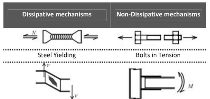
Dealing with the definition of dissipative and non-dissipative mechanisms, it is useful to note that inelasticity in steel structures can arise from different mechanisms, such as the yielding of steel due to the bending of beams or connections, the shear plasticization of panel zones and the friction due to the slippage of plates. Conversely, some examples of non-dissipative mechanisms are local buckling of members and/or of plates, yielding of low ductile materials, such as the steel of high strength bolts, and the plastic engagement of welds, which have been discovered to possess, in light of recent seismic events, low dissipation capacities. Aiming to obtain ductile structures, non-dissipative mechanisms have to be absolutely avoided and the brittle elements have to be over-strengthened with respect to the maximum actions associated with the development of the inelastic mechanisms (Table 2.2).
Tab TabTab
Tablelelele 2.2.2.2.2222. . . . Dissipative and non-dissipative mechanisms in steel structures
Dissipative mechanisms Non-Dissipative mechanisms
Theoretical and Experimental Analysis of Partial Strength Dissipative Joints in Steel Moment Resisting Frames
Dissipative mechanisms Non-Dissipative mechanisms
Yielding of Panel Zones
Plastic Hinge at Beam Ends
Plasticization in small regions Requires high Ductility
Demand
Bearing of Bolts Local Buckling of members
Slippage of plates Failure of welds
Inelastic Behavior of the connecting elements
From the above considerations, it is evident that structural local and global ductility play a role of paramount importance in current design approach. In fact, the plasticization of the dissipative zones elongates the period of vibration of the structure and increases the amount of hysteretic damping, resulting in a reduction of the seismic forces developed (Astaneh-Asl, 1995). In general, with the term local and global ductility it is intended the capacity of a structural element or of a structural system to withstand deformation in inelastic range
Theoretical and Experimental Analysis of Partial Strength Dissipative Joints in Steel Moment Resisting Frames
without significant loss of resistance. In case of MRFs, global ductility assumes the meaning of ratio between the ultimate top sway displacement, accounting for second order effects, and the top sway displacement evaluated in correspondence of the elastic limit. Moreover, the definition of local ductility of MRFs is concerned with the rotational capacity of the plastic hinges, i.e. of beam ends and/or of joints (Mazzolani & Piluso, 1996).
As a result of the importance in current approach of the ductility supply, international codes provide a classification of structures with reference to their capacity of resisting deformations in plastic field. In Eurocode 8 (CEN, 2005c) and AISC 2005 (AISC, 2005), MRFs can be designed to be less or more ductile, according to the three following categories:
• EC8:EC8:EC8:EC8: Ductility Class Low (DCL), AISC 2005AISC 2005AISC 2005:::: Ordinary Moment Frames AISC 2005 (OMF);
• EC8:EC8:EC8:EC8: Ductility Class Medium (DCM), AISC 2005AISC 2005AISC 2005:::: Intermediate Moment AISC 2005 Frames (IMF);
• EC8:EC8:EC8:EC8: Ductility Class High (DCH), AISC 2005AISC 2005AISC 2005AISC 2005:::: Special Moment Frames (SMF);
In both European and U.S. codes, provided that some requirements on strength and ductility supply are satisfied, yielding is allowed to occur either in beam, panel zone or connections. The formation of plastic hinges in columns is prohibited, made exception for base plates, column ends at the top of multi-storey frames, and in case of single multi-storey MRFs.
EC8, in general, favorites a design of MRFs which provides the development of plastic hinges at beam ends rather than in other zones. Dissipation in
beam-to-Theoretical and Experimental Analysis of Partial Strength Dissipative Joints in Steel Moment Resisting Frames
column joints is allowed but strongly limited in everyday practice. In fact, when the weak connection-strong column-strong beam design philosophy is adopted, the ductility supply and strength of connections have to be certified by experimental evidence, providing cyclic tests of joints.
AISC 2005 also favorites design of MRFs which provide the formation of plastic hinges at beam ends, but still offers the possibility to dissipate an amount of seismic input energy by the inelasticity of joints. In particular, AISC 2005 requires that both in case of full-strength and partial strength joints a “conformance demonstration” of the cyclic behavior of beam-to-column connections adopted in the Seismic Load Resisting System (SLRS) is provided by the designer. As a result, connections have to be pre-qualified in order to satisfy code requirements in terms of plastic rotation supply and flexural/shear strength, compatibly with the ductility class of the designed MRF. Therefore, designers have two alternatives: the adoption of prequalified joints or the qualification of specific details. In the former case, joints whose cyclic characteristic have already been qualified, such as the prequalified connections contained in document FEMA 350, are used. In the latter case, joint dissipative characteristics have to be demonstrated to be adequate by means of the qualification procedures contained in AISC 2005.
In reason of the desired global ductility supply, both Eurocode 8 and AISC 2005 provide some requirements regarding inelastic capacities of the dissipative zones. The idea is that, in case of DCH/SMF, the structural system is designed to behave in ductile manner when subjected to a severe seismic event. Thus, brittle mechanisms and buckling are avoided and dissipation is reached by means of inelastic behavior of plastic hinges (Table 2.3).
Theoretical and Experimental Analysis of Partial Strength Dissipative Joints in Steel Moment Resisting Frames
Table Table Table
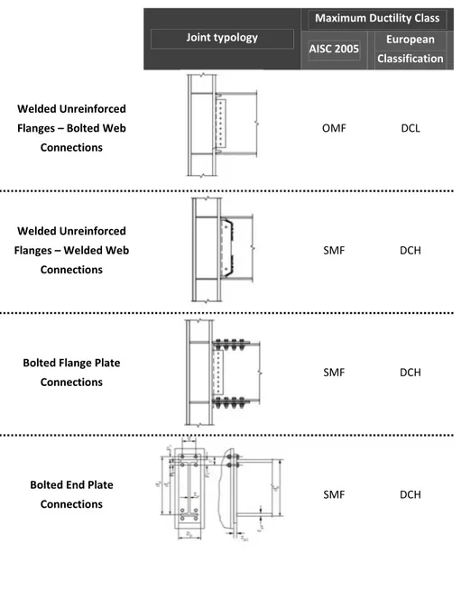
Table 2.2.2.32.333. . . Examples of pre-qualified Joint - Source: (SAC, 2000a). (SAC, 2000a)(SAC, 2000a) (SAC, 2000a)
Joint typology
Maximum Ductility Class AISC 2005 European
Classification
Welded Unreinforced Flanges – Bolted Web
Connections
OMF DCL
Welded Unreinforced Flanges – Welded Web
Connections
SMF DCH
Bolted Flange Plate
Connections SMF DCH
Bolted End Plate
Theoretical and Experimental Analysis of Partial Strength Dissipative Joints in Steel Moment Resisting Frames
Joint typology
Maximum Ductility Class
AISC 2005 European Classification
Double Split Tee
Connections SMF DCH
Reduced Beam Section
Connections SMF DCH
In particular, in AISC 2005 and EC8, connections are required to sustain an interstorey drift angle of 40 mrad and of 35 mrad respectively. In case of DCL/OMF, MRFs are expected to exhibit a low dissipative behavior and connections are not required to possess specific plastic rotation supply (Table 2.4).
Table Table Table
Table 2.2.2.2.4444. . . . Required Ductility of Connections — EC8 vs AISC 2005
Eurocode 8 AISC 2005
Ductility Class Rotational
Capacity [mrad] Ductility Class
Rotational Capacity [mrad]
Ductility Class High 35 Special Moment Frame 40 Ductility Class Medium 25 Intermediate Moment
Frame 20
Theoretical and Experimental Analysis of Partial Strength Dissipative Joints in Steel Moment Resisting Frames
In case of DCM/IMF the behavior is expected to be intermediate between high and low dissipative and, according to EC8 and AISC 2005, connections are required to sustain rotations of 25 and 20 mrad.
2.1.4 Stiffness and Strength of Joints
Fig. 2.14 – Structural Joints Configuration (CEN, 2005)
Structural joints are typically classified according to their geometry, stiffness and resistance. With reference to the geometric characteristics, (CEN, 2005b) individuate the following categories (Fig. 2.14):
1. single sided Beam-to-Column Joints; 2. double sided Beam-to-Column Joints; 3. beam splices;
4. column splices; 5. base plate joints.
Theoretical and Experimental Analysis of Partial Strength Dissipative Joints in Steel Moment Resisting Frames
Usually the words “joint” and “connection” are used likewise to individuate the region of intersection between the beam and the column. In general, with the term “connection” is usually intended the zone where the mechanical devices (bolts, plates, welds etc.), used to join the beam to the column, are located.
With the term “panel zone” is indicated the region of the column web contained within the flanges of the connected beam (Fig. 2.15). The region which includes beam-to-column connections and panel zone is called in technical literature with the word “joint” (Mazzolani & Piluso, 1996; Nethercot & Zandonini, 1990; Kirby et al., 1990; Faella et al., 2000).
Structural response of MRFs strongly depends on the behaviour of its connections. In fact, stiffness and strength of joints deeply affect dynamic properties of frames and their post-elastic behaviour. Furthermore, also the internal actions arising in the structure, both due to Serviceability and Ultimate loads, depend on the elastic and post-elastic stiffness of the connecting elements.
It is well known in technical literature that the actual flexural behaviour of a joint can be considered as intermediate between the two extreme conditions of infinitely rigid or infinitely deformable.
When the elements composing the connection, i.e. the plates, the bolts and the panel zone, are sufficiently stiff and no relative rotation between the beam and the column occurs, in design practice, the joint is usually modelled as a clamp. Conversely, when the beam is free to rotate with respect to the connected elements, the joint is usually considered as a pin. In all the other cases, i.e. when the connecting elements are neither adequately rigid to allow to model
Theoretical and Experimental Analysis of Partial Strength Dissipative Joints in Steel Moment Resisting Frames
the connection as a clamp nor so deformable to consider the beam free to rotate, the column joint is defined semi-rigid. In general, all beam-to-column connections are semi-rigid and should be modelled properly, considering their actual relationship between the bending moment and the rotation (Fig. 2.16).
Fig. 2.15 – Distinction between Connection and Panel zone
Moreover, a joint can be classified as full-strength, pinned or partial strength on the base of the relative resistance of the joint and of the connected beam. If the flexural strength of the joint is greater than the bending resistance of the beam, the connection is defined “full-strength”. Conversely, if the joint is completely incapable to withstand bending, connection is usually called “pinned”, meaning that it is only capable to transfer shear actions. In all the other cases, i.e. when the joint flexural resistance is minor than the bending strength of beam, connection is defined “partial strength”. From the standpoint
Theoretical and Experimental Analysis of Partial Strength Dissipative Joints in Steel Moment Resisting Frames
of the location of dissipative zones, different behaviors are obviously expected if full strength or partial strength connections are adopted.
Fig. 2.16 – Pinned, Continuous and Semi-continuous joints
Basically, three cases can be individuated depending on the relative resistance of beams and joints:
• plastic resistance of the beam lower than the ultimate bending resistance of the connection;
• plastic resistance of the beam greater than the ultimate bending resistance of the connection;
• plastic resistance of the beam and ultimate bending resistance of the connection balanced.
In the first case, the beam-connection overall behavior can be effectively represented with an elastic-plastic model. A plastic hinge will probably develop on the beam, while the connection will contribute only by means of its elastic stiffness. In the second case, the opposite situation will develop.
Theoretical and Experimental Analysis of Partial Strength Dissipative Joints in Steel Moment Resisting Frames
Dissipative zone is located in the connection and the overall structural behavior at ULS is influenced by joints inelastic behavior. In this case, an accurate representation of the connections moment-rotation curve is needed. In the third case, joint and beam bending strength is balanced and, as a consequence, both the elements will be engaged in plastic range under a severe seismic event, so as to the dissipation of the earthquake input energy will be relied on the inelastic behavior either of the beam and of the connection.
Within this framework, it is easy to understand that the design of connections plays a role of fundamental importance in the seismic design of MRFs. In fact, design of joints can be lead aiming to obtain different values of stiffness, strength and rotational capacity on the base of the desired overall structural behavior. As an example, if the design is aimed to obtain a weak beam-strong column — strong joint structural behavior, joints will be designed to be full strength and rigid. So that, thick plates, reinforcing ribs, doubler and continuity plates will be probably adopted to exclude from the dissipative mechanisms panel zones and connecting elements. Conversely, if the design is aimed to obtain a weak connection-strong beam-strong column behavior, joints will be designed to be partial strength and the rotational capacity of the connecting elements will have to be carefully evaluated.
It is clear from the above considerations that detailing of joint plays a role of fundamental importance within MRFs overall structural behaviour. In fact, joints ultimate behaviour can be completely modified by strengthening some elements rather than others, governing the failure mode by means of simple modifications of the joint detail.
Theoretical and Experimental Analysis of Partial Strength Dissipative Joints in Steel Moment Resisting Frames
In conclusion, as will be shown later, on the base of the classification of joints according to strength and stiffness, the following typologies of MRFs can be individuated:
• frames with full-strength rigid connections;
• frames with full-strength semi-rigid connections;
• frames with partial-strength rigid connections;