1
CHAPTER 1
OPTICAL FIBER &
DWDM TECHNOLOGY
The author welcomes you, and tries to say in a few lines why this books starts with a quick but almost detailed description of the basics of optical fiber and DWDM elements.
The PMA32 is an optical add-drop multiplexer, an apparatus which maybe represents the first attempt to largely penetrate the European DWDM optical market.
There are many ways to explain things – the best one is to give people the right key-words and languages – and I’m going to do that by this very first chapter.
1.1 PROPAGATION OF SIGNALS IN
OPTICAL FIBER
Optical fiber is a remarkable communication medium compared to other media such as copper or free space. An optical fiber provides low-loss transmission over an enormous frequency range of at least 25 THz - or even higher - which is orders of magnitude more than the bandwidth available in copper cables or any other transmission medium.
For example, this bandwidth is sufficient to transmit hundreds of millions of phone calls simultaneously, or tens of millions of Web pages per second. The low-loss property allows signals to be transmitted over long distances at high speeds before they need to be amplified or regenerated. It is due to these two properties of low loss and high bandwidth that optical fiber communication systems are so widely used today.
We are going to discuss the basics of light propagation in optical fiber, to have the means to better understand the DWDM technology in the second part of this chapter.
The main job of optical fibers is to guide lightwaves with a minimum of attenuation (loss of signal). Optical fibers are composed of fine threads of glass in layers, called the core and cladding, that can transmit light at about two-thirds the speed of light in a vacuum. Though admittedly an oversimplification, the transmission of light in optical fiber is commonly explained using the principle of total internal reflection. With this phenomenon, 100 percent of light that strikes a surface is reflected. By contrast, a mirror reflects about 90 percent of the light that strikes it. Light is either reflected (it bounces back) or refracted (its angle is altered while passing through a different medium) depending upon the angle of incidence.
Total internal reflection happens when the following conditions are met:
• Beams pass from a more dense to a less dense material.
• The incident angle is less than the critical angle. The critical angle is the angle of
incidence at which light stops being refracted and is instead totally reflected.
[2]
The principle of total internal reflection within a fiber core is illustrated in Figure 1.1. The core has a higher refractive index than the cladding, allowing the beam that strikes that surface at less than the critical angle to be reflected. The second beam does not meet the critical angle requirement and is refracted.
2
So an optical fiber consists of a cylindrical core surrounded by a cladding. Both the core and the cladding are made primarily of silica (SiO2), which has a refractive index of approximately 1.45. The refractive index of a material is the ratio of the speed of light in a vacuum to the speed of light in that material. During the manufacturing of the fiber, certain impurities (or dopants) are introduced in the core and/or the cladding so that the refractive index is slightly higher in the core than in the cladding. Materials such as germanium and phosphorous increase the refractive index of silica and are used as dopants for the core, whereas materials such as boron and fluorine that decrease the refractive index of silica are used as dopants for the cladding.
Figure 1.1 - Principle of Total Internal Reflection
1.1.1 SINGLE & MULTI-MODE FIBERS
The electric and magnetic field vectors in the core and the electric and magnetic field vectors in the cladding must satisfy the wave equations, respectively. However, the solutions in the core and the cladding are not independent; they are related by boundary conditions at the core-cladding interface.
Each fiber mode has a different propagation constant associated with it. (This is true for non-degenerate modes). The propagation constant is measured in units of radians per unit length. It determines the speed at which pulse energy in a mode propagates in the fiber. We can think of a "mode" as one possible path that a guided ray can take. Since the path lengths are different, the propagation speeds of the modes are different). The light energy propagating in the fiber will be divided among the modes supported by the fiber, and since the modes travel at different speeds in the fiber, the energy in a narrow pulse at the input of a length of fiber will be spread out at the output. Thus it is desirable to design the fiber such that it supports only a single mode. Such a fiber is called a single-mode fiber, and the mode that it supports is termed the fundamental mode.
A fiber which supports more than one mode is called a multimode fiber. A typical multimode fiber supports a few hundred propagation modes.
[1]
1.1.2 LOSS & BANDWIDTH
Let’s talk about loss in fiber optics. The two main loss mechanisms in an optical fiber are
material absorption and Rayleigh scattering. Material absorption includes absorption by
silica as well as the impurities in the fiber. The material absorption of pure silica is negligible in the entire band that is used for optical communication systems. The reduction of the loss due to material absorption by the impurities in silica has been very important in making optical fiber the remarkable communication medium that it is today. The loss has now been reduced to negligible levels at the wavelengths of interest for optical communication:0.8 µm, 1.3 µm, and 1.55 µm.
3
Figure 1.2 – Attenuation loss in silica as a function of wavelength
Figure 1.2 shows the attenuation loss in silica as a function of wavelength. We see that the loss has local minima at these three wavelength bands with typical losses of 2.5, 0.4, and 0.25 dB/km. (In a typical optical communication system, a signal can undergo a loss of about 20-30 dB before it needs to be amplified or regenerated. At 0.25 dB/km, this corresponds to a distance of 80-120 km.) The attenuation peaks separating these bands are primarily due to absorption by the residual water vapor in the silica fiber.
The usable bandwidth of optical fiber in these bands, which we can take as the bandwidth over which the loss in decibels per kilometer is within a factor of 2 of its minimum, is approximately 80 nm at 1.3 µm and 180 nm at 1.55 µm. In terms of optical frequency, these bandwidths correspond to about 35,000 GHz. This is an enormous amount of bandwidth indeed, considering that the bit rate needed for most user applications today is no more than a few tens of megabits per second.
The usable bandwidth of fiber in most of today's long-distance networks is limited by the bandwidth of the erbium-doped fiber amplifiers that are widely deployed, rather than by the bandwidth of the silica fiber. Based on the availability of amplifiers, the low-loss band at 1.55 µm is divided into three regions,as shown in Figure 1.3.
The middle band from 1530 to 1565 nm is the conventional or C-band where WDM systems have operated using conventional erbium-doped fiber amplifiers. The band from
1565 to 1625 nm, which consists of wavelengths longer than those in the C-band, is called
the L-band and is today being used in high-capacity WDM systems, with the development of gain-shifted erbium-doped amplifiers that provide amplification in this band. The band below 1530 nm, consisting of wavelengths shorter than those in the C-band, is called the S-band. Fiber Raman amplifiers provide amplification in this band.
Lucent introduced a new kind of single-mode optical fiber, called AllWave fiber, in
1998, which virtually eliminates the absorption peaks due to water vapor. This fiber has an
even larger bandwidth and is expected to be deployed in metropolitan-area networks that do not use erbium-doped fiber amplifiers.
4
Figure 1.3 - The three bands, S-band, C-band, and L-band, based on amplifier availability, within the low-loss region around 1.55 µm in silica fiber.
As we saw earlier in this section, the dominant loss mechanism in optical fiber is Rayleigh scattering. Rayleigh scattering arises because of fluctuations in the density of the medium (silica) at the microscopic level.
Optical fibers need to be bent for various reasons both when deployed in the field and particularly within equipment. Bending leads to "leakage" of power out of the fiber core into the cladding, resulting in additional loss. A bend is characterized by the bend radius, which is the radius of curvature of the bend (radius of the circle whose arc approximates the bend). The "tighter" the bend, the smaller the bend radius and the larger the loss. The bend radius must be of the order of a few centimeters in order to keep the bending loss low. Also, the bending loss at 1550 nm is higher than at 1310 nm. The ITU-T standards specify that the additional loss at 1550 nm due to bending must be in the range 0.5-1 dB, depending on the fiber type, for 100 turns of fiber wound with a radius of 37.5 mm. Thus a bend with a radius of 4 cm results in a bending loss of < 0.01 dB. However, the loss increases rapidly as the bend radius is reduced, so that care must be taken to avoid sharp bends, especially within equipment.
1.1.3 CHROMATIC DISPERSION
Dispersion is the name given to any effect wherein different components of the transmitted signal travel at different velocities in the fiber, arriving at different times at the receiver. Chromatic dispersion is – in other words - the term given to the phenomenon by which different spectral components of a pulse travel at different velocities. To understand the effect of chromatic dispersion, we will restrict our discussion to single-mode fiber since in the case of multimode fiber, the effects of intermodal dispersion usually overshadow that of chromatic dispersion. So the propagation constant in our discussions will be that associated with the fundamental mode of the fiber.
[3]
Chromatic dispersion arises for two reasons. The first is that the refractive index of silica, the material used to make optical fiber, is frequency dependent. Thus different frequency components travel at different speeds in silica. This component of chromatic dispersion is
5
termed material dispersion. Although this is the principal component of chromatic dispersion for most fibers, there is a second component, called waveguide dispersion. To understand the physical origin of waveguide dispersion, we have to know that the light energy of a mode propagates partly in the core and partly in the cladding. If most of the power is contained in the core, the effective index is closer to the core refractive index; if most of it propagates in the cladding, the effective index is closer to the cladding refractive index. The power distribution of a mode between the core and cladding of the fiber is itself a function of the wavelength. More accurately, the longer the wavelength, the more power in the cladding. Thus, even in the absence of material dispersion - so that the refractive indices of the core and cladding are independent of wavelength - if the wavelength changes, this power distribution changes, causing the effective index or propagation constant of the mode to change. This is the physical explanation for waveguide dispersion.
1.2 OPTICAL COMPONENTS
In this section we will discuss the physical principles behind the operation of the most important components of optical communication systems.
For each component, we will try to elaborate a simple description to better understand the following operative chapters about the Marconi PMA32.
The components used in modern optical networks include couplers, lasers, photodetectors, optical amplifiers, optical switches, filters and multiplexers. Couplers are simple components used to combine or split optical signals. After describing couplers, we will cover filters and multiplexers, which are used to multiplex and de-multiplex signals at different wavelengths in WDM systems. We will then describe various types of optical amplifiers, which are key elements used to overcome fiber and other component losses and, in many cases, can be used to amplify signals at multiple wavelengths. Understanding filters and optical amplifiers is essential to understanding the operation of lasers, which comes next. Then we will discuss photodetectors, which convert the optical signal back into the electrical domain. This is followed by optical switches, which play an important role as optical networks become more agile. Finally, we will cover wavelength converters, which are used to convert signals from one wavelength to another, at the edges of the optical network, as well as inside the network.
1.2.1 COUPLERS
The coupler is typically built by fusing two fibers together. It can also be built using waveguides in integrated optics.
Figure 1.4 – Optical coupler scheme
A directional coupler is used to combine and split signals in an optical network.
A 2 x 2 coupler (Figure 1.4) consists of two input ports and two output ports. The most commonly used couplers are made by fusing two fibers together in the middle - these are
6
called fused fiber couplers. Couplers can also be fabricated using waveguides in integrated optics. A 2 x 2 coupler, shown in figure, takes a fraction of the power from input 1 and places it on output 1 and the remaining fraction on output 2. Likewise, a fraction of the power from input 2 is distributed to output 1 and the remaining power to output 2. The coupler can be designed to be either wavelength selective or wavelength
independent. A coupler is a versatile device and has many applications in an optical network. The simplest application is to combine or split signals in the network. For example, a coupler can be used to distribute an input signal equally among two output ports if the coupling length, l in Figure 1.4, is adjusted such that half the power from each input appears at each output. Such a coupler is called a 3 dB coupler.
Figure 1.5 – Star coupler
A star coupler (Figure 1.5) with eight inputs and eight outputs can be made by combining 3 dB couplers. The power from each input is split equally among all the outputs. A star coupler is useful when multiple signals need to be combined and broadcast to many outputs. However, other constructions of an n x n coupler in integrated optics are also possible.
Couplers are the building blocks for several other optical devices.
Couplers are also the principal components used to construct Mach-Zehnder
interferometers, which can be used as optical filters, multiplexers/demultiplexers, or as
building blocks for optical modulators, switches, and wavelength converters.
So far, we have looked at wavelength-independent couplers. A coupler can be made wavelength selective, meaning that its coupling coefficient will then depend on the wavelength of the signal. Such couplers are widely used to combine signals at 1310 nm and 1550 nm into a single fiber without loss. In this case, the 1310 nm signal on input 1 is passed through to output 1, whereas the 1550 nm signal on input 2 is passed through also to output 1. The same coupler can also be used to separate the two signals coming in on a common fiber.
7
1.2.2 ISOLATORS & CIRCULATORS
Couplers and most other passive optical devices are reciprocal devices, in that the devices work exactly the same way if their inputs and outputs are reversed. However, in many systems there is a need for a passive nonreciprocal device.
An isolator is an example of such a device. Its main function is to allow transmission in one direction through it but block all transmission in the other direction. Isolators are used in systems at the output of optical amplifiers and lasers primarily to prevent reflections from entering these devices, which would otherwise degrade their performance.
The two key parameters of an isolator are its insertion loss, which is the loss in the forward direction, and which should be as small as possible, and its isolation, which is the loss in the reverse direction, and which should be as large as possible. The typical insertion loss is around 1 dB, and the isolation is around 40-50 dB.
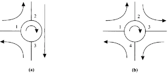
Figure 1.6 - Three-port (a) and four-port (b) optical Circulators
A circulator is similar to an isolator, except that it has multiple ports, typically three or four,
as shown in Figure 1.6. In a three-port circulator, an input signal on port 1 is sent out on port 2, an input signal on port 2 is sent out on port 3, and an input signal on port 3 is sent out on port 1. Circulators are useful to construct optical add/drop elements, as we will see later in this chapter, and in the PMA32 itself.
1.2.3 WAVELENGTH MULTIPLEXERS & FILTERS
In this section, we will study the principles underlying the operation of a variety of wavelength selection technologies. Optical filters are essential components in transmission systems for at least two applications: to multiplex and de-multiplex wavelengths in a WDM system - these devices are called multiplexers/demultiplexers - and to provide equalization of the gain and filtering of noise in optical amplifiers. Further, understanding optical filtering is essential to understanding the operation of lasers later in this chapter.
The different applications of optical filters are shown in Figure 1.7.
Figure 1.7 (a) shows a simple filter, which selects one wavelength and either blocks the remaining wavelengths or makes them available on a third port. Figure 1.7 (b) shows a multiplexer, which combines multiple wavelengths into a single fiber. In the reverse direction, the same device acts as a demultiplexer to separate the different wavelengths.
8
Figure 1.7 - Different applications for optical filters in optical networks .
So we can say that a simple filter is a two-port device that selects one wavelength and rejects all others. It may have an additional third port on which the rejected wavelengths can be obtained. Instead a multiplexer combines signals at different wavelengths on its input ports onto a common output port, and a demultiplexer performs the opposite function. Multiplexers and demultiplexers are used in WDM terminals as well as in larger
wavelength cross-connects and wavelength add-drop multiplexers.
Demultiplexers and multiplexers can be cascaded to realize static wavelength cross-connects (WXCs). In a static WXC, the cross-connect pattern is fixed at the time the device is made and cannot be changed dynamically. Figure 1.8 shows an example of a static WXC. The device routes signals from an input port to an output port based on the wavelength. Dynamic WXCs can be constructed by combining optical switches with multiplexers and demultiplexers. Static WXCs are highly limited in terms of their functionality. For this reason, the devices of interest are dynamic rather than static WXCs.
Figure 1.8 - A static wavelength cross-connect
The Marconi PMA32, which was designed to be a static add-drop multiplexer, with functions of static WXC can be, for example, made dynamic by using optical switches, so to make it capable to switch different wavelengths. This problem has been solved in the new generations of Marconi’s add-drop multiplexers and optical technologies.
A variety of optical filtering technologies are available. [4]
Among all the performance parameters, perhaps the most important consideration is cost. Technologies that require careful hand assembly tend to be more expensive. There are two ways of reducing the cost of optical filters. The first is to fabricate them using integrated-optic waveguide technology. This is analogous to semiconductor chips,
9
although the state of integration achieved with optics is significantly less. These waveguides can be made on many substrates, including silica, silicon, InGaAs, and polymers.
The second method is to realize all-fiber devices. Such devices are amenable to mass production. It is also easy to couple light in and out of these devices from/into other fibers. Both of these approaches are being pursued today.
1.2.4 DIFFRACTION & REFLECTION GRATINGS
Figure 1.9 - (a) A transmission grating and (b) a reflection grating.
Gratings have been widely used for centuries in optics to separate light into its constituent wavelengths. In WDM communication systems, gratings are used as demultiplexers to separate the individual wavelengths or as multiplexers to combine them.
Consider the grating shown in Figure 1.9 (a). Multiple narrow slits are spaced equally apart on a plane, called the grating plane. The spacing between two adjacent slits is called the pitch of the grating. Light incident from a source on one side of the grating is transmitted through these slits. Since each slit is narrow, by the phenomenon known as
diffraction, the light transmitted through each slit spreads out in all directions. Thus each
slit acts as a secondary source of light. Consider some other plane parallel to the grating plane at which the transmitted light from all the slits interferes. We will call this plane the
imaging plane. Consider any point on this imaging plane. For wavelengths for which the
individual interfering waves at this point are in phase, we have constructive interference and an enhancement of the light intensity at these wavelengths. For a large number of slits, which is the case usually encountered in practice, the interference is not constructive at other wavelengths, and there is little light intensity at this point from these wavelengths. Since different wavelengths interfere constructively at different points on the imaging plane, the grating effectively separates a WDM signal spatially into its constituent wavelengths. In a fiber optic system, optical fibers could be placed at different imaging points to collect light at the different wavelengths.
Note that if there were no diffraction, we would simply have light transmitted or reflected along the directed dotted lines in Figure 1.9 (a) and (b). Thus the phenomenon of diffraction is key to the operation of these devices, and for this reason they are called
10
grating is called a transmission grating. If the transmission slits are replaced by narrow reflecting surfaces, with the rest of the grating surface being nonreflecting, we get the
reflection grating of Figure 1.9 (b). The principle of operation of this device is exactly analogous to that of the transmission grating. A majority of the gratings used in practice are reflection gratings since they are somewhat easier to fabricate. In addition to the plane geometry we have considered, gratings are fabricated in a concave geometry. In this case, the slits (for a transmission grating) are located on the arc of a circle. In many applications, a concave geometry leads to fewer auxiliary parts like lenses and mirrors needed to construct the overall device.
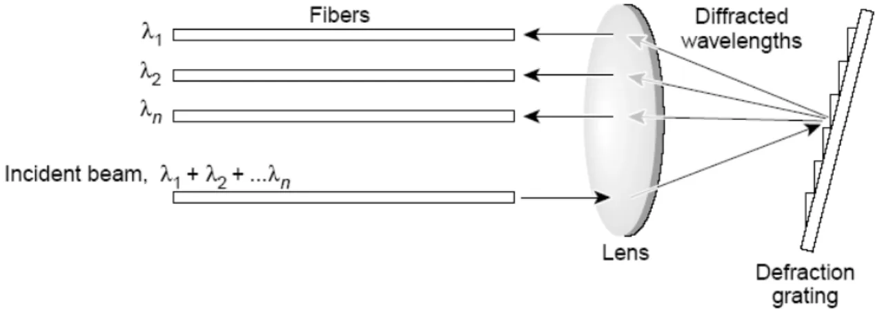
Figure 1.10 shows the obtained signals on the different fiber cables, after the diffraction mechanism due to a simple lens and to the already seen grating.
Figure 1.10 – A lens and the obtained wavelength
Fiber Gratings
Fiber gratings are attractive devices that can be used for a variety of applications, including filtering and add/drop functions. Being all-fiber devices, their main advantages are their low loss, ease of coupling (with other fibers), polarization insensitivity, low temperature coefficient, and simple packaging. As a result, they can be extremely low-cost devices.
Gratings are written in fibers by making use of the photosensitivity of certain types of optical fibers. A conventional silica fiber doped with germanium becomes extremely photosensitive. Exposing this fiber to ultraviolet (UV) light causes changes in the refractive index within the fiber core. A grating can be written in such a fiber by exposing its core to two interfering UV beams. This causes the radiation intensity to vary periodically along the length of the fiber. Where the intensity is high, the refractive index is increased; where it is low, the refractive index is unchanged. The change in refractive index needed to obtain gratings is quite small.
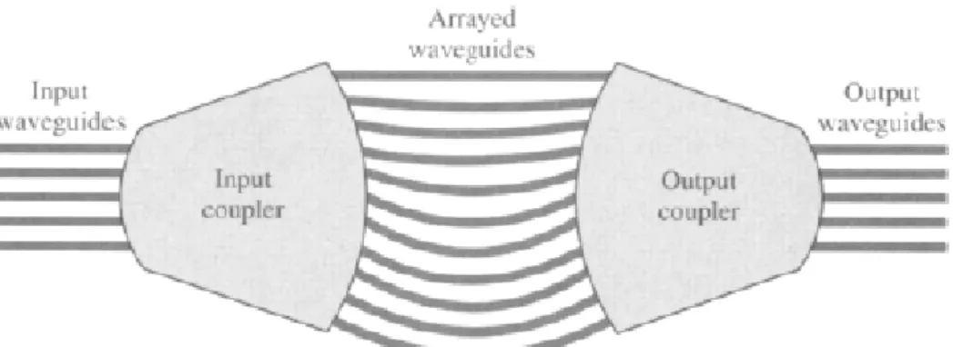
1.2.5 HIGH CHANNEL COUNT MULTIPLEXER ARCHITECTURES
With the number of wavelengths continuously increasing, designing multiplexers and demultiplexers to handle large numbers of wavelengths has become an important problem. Our discussion will be based on demultiplexers, but these demultiplexers can all be used as multiplexers as well. In fact, in bidirectional applications, where some wavelengths are transmitted in one direction over a fiber and others in the opposite direction over the same fiber, the same device acts as a multiplexer for some wavelengths and a demultiplexer for
11
others. We are going to describe several architectural approaches to construct high channel count demultiplexers.
1) Serial Architecture DEMUX
In this approach, the demultiplexing is done one wavelength at a time. The demultiplexer consists of filter stages in series, one for each of the wavelengths. [5]
Each filter stage demultiplexes a wavelength and allows the other wavelengths to pass through. The architecture shown in Figure 1.11 is an example.
Figure 1.11 – Example of Serial Architecture DEMUX
One advantage of this architecture is that the filter stages can potentially be added one at a time, as more wavelengths are added. This allows a "pay as you grow" approach.
Serial approaches work for demultiplexing relatively small numbers of channels but do not scale to handle a large number of channels. This is because the insertion loss (in decibels) of the demultiplexer increases almost linearly with the number of channels to be demultiplexed. Moreover, different channels see different insertion losses based on the order in which the wavelengths are demultiplexed, which is not a desirable feature.
2) Single-Stage Architecture DEMUX
Figure 1.12 – Example of Single-Stage Architecture DEMUX
Here, all the wavelengths are demultiplexed together in a single stage.
12
This approach provides relatively lower losses and better loss uniformity, compared to the serial approach.
However, the number of channels that can be demultiplexed is limited by the maximum number of channels that can be handled by a single device.
3) Multistage Banding Architecture DEMUX
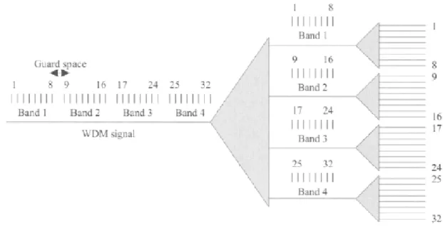
Going to larger channel counts requires the use of multiple demultiplexing stages, due to the limitations of the serial and single-stage approaches discussed above. A popular approach used today is to divide the wavelengths into bands. For example, a total of 32 wavelengths may be divided into four bands, each with 8 wavelengths.
Figure 1.13 - Multistage Banding Architecture DEMUX
The demultiplexing is done in two stages, as shown in Figure 1.13. In the first the set of wavelengths is demultiplexed into bands. In the second stage, the bands are demultiplexed, and individual wavelengths are extracted. The scheme can be extended to more than two stages as well. It is also modular in that the demultiplexers in the second stage (or last stage in a multistage scheme) can be populated one band at a time.
One drawback with the banding approach is that we will usually need to leave a "guard" space between bands, as shown in figure.
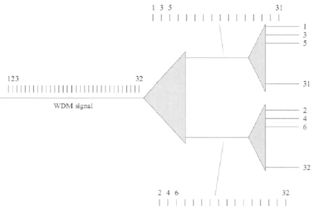
4) Multistage Interleaving Architecture DEMUX
Interleaving provides another approach to realizing large channel count demultiplexers. A two-stage interleaver is shown in Figure 1.14. In this approach the first stage separates the wavelengths into two groups. The first group consists of wavelengths 1, 3, 5… and the second group consists of wavelengths 2, 4, 6… The second stage extracts the individual wavelengths. This approach is also modular in the sense that the last stage of demultiplexers can be populated as needed. More than two stages can be used if needed as well.
13
Figure 1.14 - Multistage Interleaving Architecture DEMUX
A significant benefit of this approach is that the filters in the last stage can be much wider than the channel width. As an example, suppose we want to demultiplex a set of 32 channels spaced 50 GHz apart. After the first stage of demultiplexing, the channels are spaced 100 GHz apart. So demultiplexers with a broader passband suitable for demultiplexing 100 GHz spaced channels can be used in the second stage. In contrast, the single-stage or serial approach would require the use of demultiplexers capable of demultiplexing 50 GHz spaced channels, which are much more difficult to build.
1.2.6 OPTICAL AMPLIFIERS
In an optical communication system, the optical signals from the transmitter are attenuated by the optical fiber as they propagate through it. Other optical components, such as multiplexers and couplers, also add loss. After some distance, the cumulative loss of signal strength causes the signal to become too weak to be detected. Before this happens, the signal strength has to be restored. Prior to the advent of optical amplifiers over the last decade, the only option was to regenerate the signal, that is, receive the signal and retransmit it. This process is accomplished by regenerators.
A regenerator converts the optical signal to an electrical signal, cleans it up, and converts it back into an optical signal for onward transmission.
Optical amplifiers offer several advantages over regenerators. Regenerators are specific to the bit rate and modulation format used by the communication system. On the other hand, optical amplifiers are insensitive to the bit rate or signal formats. Thus a system using optical amplifiers can be more easily upgraded, for example, to a higher bit rate, without replacing the amplifiers. In contrast, in a system using regenerators, such an upgrade would require all the regenerators to be replaced. Furthermore, optical amplifiers have fairly large gain bandwidths, and as a consequence, a single amplifier can simultaneously amplify several WDM signals. In contrast, we would need a regenerator for each wavelength.
14
Thus optical amplifiers have become essential components in high-performance optical communication systems.
Amplifiers, however, aren't perfect devices. They introduce additional noise, and this noise accumulates as the signal passes through multiple amplifiers along its path due to the analog nature of the amplifier. The spectral shape of the gain, the output power, and the transient behavior of the amplifier are also important considerations for system applications. Ideally we would like to have a sufficiently high output power to meet the needs of the network application. We would also like the gain to be flat over the operating wavelength range, and for the gain to be insensitive to variations in input power of the signal.
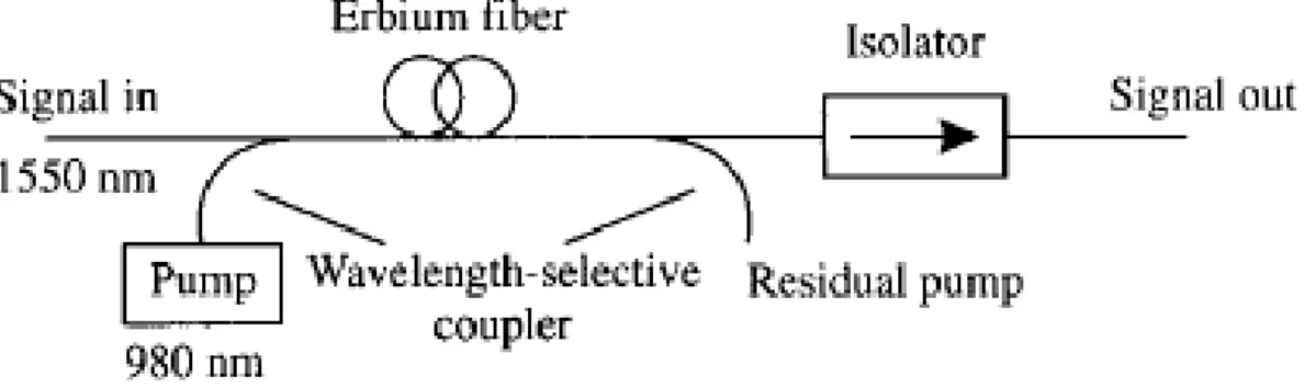
Erbium-Doped Fiber Amplifiers (EDFA’s)
An erbium-doped fiber amplifier (EDFA) is shown in Figure 1.15.
Figure 1.15 – EDFA architecture
It consists of a length of silica fiber whose core is doped with ionized atoms (ions), Er 3+, of the rare earth element erbium. This fiber is pumped using a pump signal from a laser, typically at a wavelength of 980 nm or 1480 nm. In order to combine the output of the pump laser with the input signal, the doped fiber is preceded by a wavelength-selective coupler. At the output, another wavelength-selective coupler may be used if needed to separate the amplified signal from any remaining pump signal power. Usually, an isolator is used at the input and/or output of any amplifier to prevent reflections into the amplifier. A combination of several factors has made the EDFA the amplifier of choice in today's optical communication systems: (1) the availability of compact and reliable high-power semiconductor pump lasers, (2) the fact that it is an all-fiber device, making it easy to couple light in and out of it, (3) the simplicity of the device, and (4) the fact that it introduces no crosstalk when amplifying WDM signals.
And last but not least, the EDFA amplifiers are included in the PMA32 architecture, as we are going to see in the operative chapters of this book. [7]
Multistage Designs
In practice, most amplifiers deployed in real systems are more complicated than the simple structure shown in Figure 1.15. There are more commonly used two-stage designs. The two stages are optimized differently. The first stage is designed to provide high gain and low noise, and the second stage is designed to produce high output power.
15
Semiconductor Optical Amplifiers (SOA’s)Semiconductor optical amplifiers (SOA’s) actually preceded EDFA’s, although they are not as good as EDFAs for use as amplifiers. However, they are finding other applications in switches and wavelength converter devices. The SOA is essentially a p n-junction.
1.2.7 OPTICAL TRANSMITTERS
Lasers
The most important source of light is the laser, of which there are many different types. Lasers are used as transmitters and also to pump erbium-doped amplifiers.
Lasers need to produce a reasonably high output power. For WDM systems, the typical laser output powers are in the 0-10 dBm range. Related parameters are the threshold current and slope efficiency. Both of these govern the efficiency of converting electrical power into optical power. The threshold current is the drive current at which the laser starts to emit optical power, and the slope efficiency is the ratio of output optical power to drive current. Wavelength stability is another important criterion.
A laser is essentially an optical amplifier enclosed within a reflective cavity.
Semiconductor lasers use semiconductors as the gain medium, whereas fiber lasers
typically use erbium-doped fiber as the gain medium. Semiconductor lasers are by far the most popular light sources for optical communication systems.
Since they are essentially p n-junctions, they can be fabricated in large volumes using highly advanced integrated semiconductor technology. Semiconductor lasers are also highly efficient in converting input electrical (pump) energy into output optical energy. As we know from Electronics, beyond a certain threshold called lasing threshold, the p n-junction device is no longer an amplifier but an oscillator or laser.
The term laser is an acronym for light amplification by stimulated emission of radiation. [6]
Light-Emitting Diodes
Lasers are expensive devices and are not affordable for many applications where the data rates are low and distances are short. This is the case in many data communications applications. In such cases, light-emitting diodes (LED’s) provide a cheaper alternative. A LED is a p n-junction in which the recombination of the injected minority carriers by the spontaneous emission process produces light.
Tunable Lasers
Tunable lasers are highly desirable components for WDM networks for several reasons. Fixed-wavelength lasers work very well for today's applications. However, each wavelength requires a different, unique laser. This implies that in order to supply a 100-channel WDM system, we need to stock 100 different laser types. The inventory and sparing issues associated with this are expensive and affect everybody from laser manufacturers to network operators. Laser manufacturers need to set up multiple production and test lines for each laser. Equipment suppliers need to stock these different lasers and keep inventories and spares for each wavelength. Finally, network operators need to stockpile spare wavelengths in the event transmitters fail in the field and need to be replaced.
16
Having a tunable laser alleviates this problem dramatically. Tunable lasers are also one of the key enablers of reconfigurable optical networks.
They provide the flexibility to choose the transmit wavelength at the source of a light-path. For instance, if we wanted to have a total of four light-paths starting at a node, we would equip that node with four tunable lasers. This would allow us to choose the four transmit wavelengths in an arbitrary manner. In contrast, if we were to use fixed-wavelength lasers, either we would have to pre-equip the node with a large number of lasers to cover all the possible wavelengths, or we would have to manually equip the appropriate wavelength as needed. The tuning time required for such applications is on the order of milliseconds because the wavelength selection happens only at the times where the light-path is set up, or when it needs to be rerouted in the event of a failure.
Another application for tunable lasers is in optical packet-switched networks, where data needs to be transmitted on different wavelengths on a packet-by-packet basis. These networks are primarily in their early stages of research today, but supporting such an application would require tuning times on the order of nanoseconds to microseconds, depending on the bit rate and packet size used.
Tunable lasers are included in the Marconi PMA32 technology.
The Lasers Modulation Process
The process of imposing data on the light stream is called modulation. The simplest and most widely used modulation scheme is called on-off keying (OOK), where the light stream is turned on or off, depending on whether the data bit is a 1 or 0.
OOK modulated signals are usually realized in one of two ways: (1) by direct modulation of a semiconductor laser or a LED, or (2) by using an external modulator.
In the direct modulation process, the drive current into the semiconductor laser is set well above threshold for a 1 bit and below threshold for a 0 bit. Direct modulation is simple and inexpensive since no other components are required for modulation other than the light source (laser/LED) itself.
Instead some lasers require an external modulator. In this case, an OOK external modulator is placed in front of a light source and turns the light signal on or off based on the data to be transmitted.
1.2.8 OPTICAL DETECTORS
Figure 1.16 – Block diagram of a receiver in optical communications
A receiver converts an optical signal into a usable electrical signal. Figure 1.16 shows the different components within a receiver. The photodetector generates an electrical current proportional to the incident optical power. The front-end amplifier increases the power of the generated electrical signal to a usable level. In digital communication systems, the front-end amplifier is followed by a decision circuit that estimates the data from the output of the front-end amplifier. The design of this decision circuit depends on the modulation scheme used to transmit the data.
An optical amplifier may be optionally placed before the photodetector to act as a
17
Photodetectors are made of semiconductor materials. Photons incident on a semiconductor are absorbed by electrons. As a result, these electrons acquire higher energy and are excited, leaving behind a hole. When an external voltage is applied to the semiconductor, these electron-hole pairs give rise to an electrical current, termed the
photocurrent.
1.2.9 OPTICAL SWITCHES
Optical switches are used in optical networks for a variety of applications.
One application of optical switches is in the provisioning of light-paths. In this application, the switches are used inside wavelength cross-connects to reconfigure them to support new lightpaths. In this application, the switches are replacements for manual fiber patch panels, but with significant added software for end-to-end network management.
Another important application is that of protection switching. Here the switches are used to switch the traffic stream from a primary fiber onto another fiber in case the primary fiber fails.
Automatic protection switching one of the main innovative solutions included in the Marconi PMA32.
The entire operation must typically be completed in several tens of milliseconds, which includes the time to detect the failure, communicate the failure to the appropriate network elements handling the switching, and the actual switch time.
Switches are also important components in high-speed optical packet-switched networks. In these networks, switches are used to switch signals on a packet-by-packet basis. Switches with port counts ranging from a few hundred to a few thousand are being sought by carriers for their next-generation networks. Given that a single central office handles multiple fibers, with each fiber carrying several tens to hundreds of wavelengths, it is easy to imagine the need for large-scale switches to provision and protect these wavelengths.
Crossbar Switches
A 4 x 4 crossbar switch is shown in Figure 1.17. This switch uses 16 2 x 2 switches, and the interconnection between inputs and outputs is achieved by appropriately setting the states of these 2 x 2 switches.
To connect input i to output j , the path taken traverses the 2 x 2 switches in row i till it reaches column j and then traverses the switches in column j till it reaches output j. Thus the 2 x 2 switches on this path in row i and column j must be set appropriately for this connection to be made.
In general, an n • n crossbar requires n 2 2 • 2 switches.
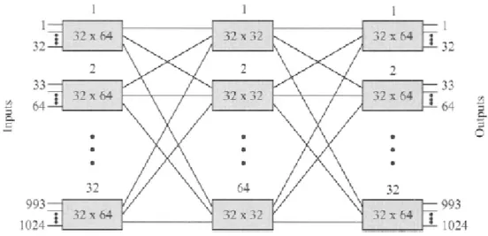
Clos Switches
The Clos architecture is widely used in practice to build large port count switches. A three-stage 1024-port Clos switch is shown in Figure 1.18.
18
Figure 1.17 – Crossbar switch
An n x n switch is constructed as follows. We use three
parameters, m, k, and p. Let n - m k . The first and third stage consist of k (m x p) switches. The middle stage consists of p (k x k) switches. Each of the k switches in the first stage is connected to all the switches in the middle stage. (Each switch in the first stage has p outputs. Each output is connected to the input of a different switch in the middle stage.) Likewise, each of the k switches in the third stage is connected to all the switches in the middle stage.
If p >__ 2m - 1, the switch is strictly non-blocking.
Usually the individual switches in each stage are designed using crossbar switches.
Figure 1.18 - 1024 • 1024 switch using 32 x 64 and 32 x 32 switches interconnected in a three-stage Clos architecture
With this topology the number of switch elements require a cost which is significantly lower than the one required for a crossbar.
19
Micro-Electro-Mechanical System (MEMS) SwitchesThe crossbar architecture is also used in the MEMS switches. Micro-electro-mechanical systems (MEMS) are miniature mechanical devices typically fabricated using silicon substrates. In the context of optical switches, MEMS usually refers to miniature movable mirrors fabricated in silicon, with dimensions ranging from a few hundred micrometers to a few millimeters.
These mirrors are deflected from one position to another using a variety of electronic actuation techniques, such as electromagnetic, electrostatic, or piezoelectric methods, hence the name MEMS.
The simplest mirror structure is a so-called two-state pop-up mirror, or 2D mirror, shown in Figure 1.19.
Figure 1.19 – A 2D mirror
In one state, the mirror is flat in line with the substrate. In this state, the light beam is not deflected. In the other state, the mirror pops up to a vertical position and the light beam if present is deflected.
Another type of mirror structure is shown in Figure 1.20. The mirror is connected through flexures to an inner frame, which in turn is connected through another set of flexures to an outer flame. The flexures allow the mirror to be rotated freely on two distinct axes. This mirror can be controlled in an analog fashion to realize a continuous range of angular deflections. This type of mirror is sometimes referred to as a 3D mirror.
20
The control of these mirrors is not a trivial matter, with fairly sophisticated mechanisms required to deflect the mirrors to their correct position and hold them there.
As we’ll see analyzing the PMA32, some MEMS switches could be used to make a PMA-based network even more dynamic and reconfigurable by any software but the one offered by Marconi when this should be requested or useful.
1.2.10 WAVELENGTH CONVERTERS (TRANSPONDERS)
A wavelength converter is a device that converts data from one incoming wavelength to another outgoing wavelength. Wavelength converters are useful components in WDM networks for three major reasons.
First, data may enter the network at a wavelength that is not suitable for use within the network. A wavelength converter used to perform this function is sometimes called a transponder. Transponder is the name we’ll use in the next chapters when talking about the PMA32. Actually every card in the PMA32 is a transponder/wavelength converter, as it convert any signal from a frequency to the one it’s supposed to apply.
Second, wavelength converters may be needed within the network to improve the utilization of the available wavelengths on the network links.
Finally, wavelength converters may be needed at boundaries between different networks if the different networks are managed by different entities and these entities do not coordinate the allocation of wavelengths in their networks.
There are four fundamental ways of achieving wavelength conversion: (1) optoelectronic, (2) optical gating, (3) interferometric, and (4) wave mixing.
The latter three approaches are all-optical but not yet mature enough for commercial use. In fact the PMA32 was planned with opto-electronic converters.
Optoelectronic converters today offer substantially better performance at lower cost than comparable all-optical wavelength converters.
21
1.3 WDM ALL-OPTICAL NETWORKS
1.3.1 COMPARING OPTICAL POINT-TO-POINT LINKS
AND COMPLEX OPTICAL NETWORKS
All-optical networks consist of optical fiber links between nodes with all-optical switching and routing of signals at the nodes, without electronic regeneration.
Designing networks is obviously significantly harder than designing point-to-point links, and this is mainly due to the following reasons:
- The reach required for all-optical networks is considerably more than the reach required for point-to-point links, since light-paths must traverse multiple links. In addition, loss, chromatic dispersion, and nonlinearities do not get reset at each node.
- Misalignment of multiplexers and demultiplexers along the path is a big problem more in networks than in links.
- Because of bandwidth narrowing of cascaded multiplexers and demultiplexers, the requirements on laser wavelength stability and accuracy are much higher than in point-to-point links.
- The system designer must deal with the variation of signal powers and signal-to-noise ratios among different light-paths travelling through different numbers of nodes and having different path lengths. This can make system design particularly difficult. A common approach used to solve this problem is to equalize the powers of each channel at each node individually. Thus, at each node the powers in all the channels are set to a common value. This ensures that all light-paths reach their receivers with the same power, regardless of their origin or their path through the network.
We’ll notice during our PMA32 discovery that power levels are actually very irregular and difficult to be managed in case of system failure or damage.
- For the reasons just explained, rapid dynamic equalization of the amplifier gains will be needed to compensate for fluctuations in optical power as light-paths are taken down or set up, or in the event of failures.
1.3.2 WAVELENGTH PLANNING IN WDM & IN THE PMA32
The International Telecommunications Union (ITU) has been active in trying to standardize a set of wavelengths for use in WDM networks. This is necessary to ensure eventual interoperability between systems from different vendors (although this is very far away). An important reason for setting these standards is to allow component vendors to manufacture to a fixed standard, which allows volume cost reductions, as opposed to producing custom designs for different system vendors.
The channels, according to ITU standards, are to be placed in a 50 GHz grid – as you can see in Figure 1.22 - (0.4 nm wavelength spacing) with a nominal center frequency of 193.1 THz (1552.52 nm) in the middle of the 1.55 µm fiber.
Other possibilities can be chosen: for example, a system using the channels 193.1,193.2, 193.3, and 193.4 THz is spaced on a 100 GHz grid and the channel spacings are all equal to 100 GHz. This is the case of our PMA32.
A difficult decision is to pick a standard set of wavelengths for use in 4-, 8-, 16-, and 32-wavelength systems to ensure interoperability.
22
Figure 1.22 - Wavelength grid selected by the ITU
This is because different manufacturers have different optimized channel configurations and different upgrade plans to go from a system with a small number of channels to a system with a larger number of channels.
At the time of projecting the first prototypes of PMA32, ITU had standardized (ITU G.959) the set of 16 wavelengths starting with 192.1 THz, and spaced 200 GHz apart, for multichannel interfaces between WDM equipment.
The PMA32 itself was projected starting with 192.1 THz but with 32 wavelengths and a 100 GHz spacing. A complete list of the frequencies involved, together with tolerance and nm wavelengths can be found in the chapter introducing the PMA32 itself.
1.3.3 TRANSPARENCY ADVANTAGES IN WDM SYSTEMS
Among the advantages in WDM systems is the fact that they are transparent to bit rate, protocol, and modulation formats. It is true to a large extent that a wavelength can carry arbitrary data protocols. Providing transparency to bit rate and modulation formats is much more difficult. For instance, analog transmission requires much higher signal-to-noise ratios and linearity in the system than digital transmission and is much more susceptible to impairments. A WDM system can be designed to operate at a maximum bit rate per channel and can support all bit rates below that maximum. Thus the system must be designed up front to support the maximum possible bit rate.
1.3.4 CLIENT LAYERS OF THE OPTICAL NETWORK
In this paragraph we are going to shortly explain several networks that use optical fiber as their underlying transmission mechanism. These networks can be thought of as client layers of the optical layer. As we know, the optical layer provides light-paths to the client layers. To the client layer, these light-paths look like simple physical links between client layer network elements. All the client layers process the data in the electrical domain, performing functions such as fixed time division multiplexing or statistical time division multiplexing (packet switching). These client layers aggregate and bring a variety of lower-speed voice, data, and private line services into the network. Each of these client networks is important in its own right and can operate over point-to-point fiber links as well as over a more sophisticated optical layer, using the lightpaths provided by the optical layer. [9]
The predominant standards in backbone networks today are SONET/SDH, IP, and ATM. SONET/SDH is particularly adept at dealing with lower-speed time division multiplexed streams, whereas IP and ATM are adept at dealing with statistically multiplexed packet streams. In many cases, IP and ATM use SONET/SDH as the underlying transport mechanism. With the emergence of high-speed interfaces on IP and ATM equipment, we
23
are also seeing IP and ATM mapped directly into the optical layer, without requiring separate SONET/SDH equipment.
SONET & SDH
SONET (Synchronous Optical Network) is the current transmission and multiplexing standard for high-speed signals within the carrier infrastructure in North America.
A closely related standard, SDH (Synchronous Digital Hierarchy), has been adopted in Europe and Japan and for most submarine links.
Both standards have always been used as multiplexing-demultiplexing systems to transport voice traffic.
Prior to SONET and SDH, the existing infrastructure was based on the plesiochronous
digital hierarchy (PDH), dating back to the mid-1960s.
PDH suffered from several problems, which led carriers and vendors alike to seek a new transmission and multiplexing standard in the late 1980s. This resulted in the SONET/SDH standards, which solved many problems associated with PDH.
Nowadays SONET/SDH systems are still very common and they are used over the optical layer infrastructure: here is the reason why they are a client layer.
ATM
Voice and data networks have traditionally been separate even though almost the entire telephone network is digital.
ATM (asynchronous transfer mode) is a networking standard that was developed with many goals, one of which was the integration of voice and data networks. An ATM network uses packets or cells with a fixed size of 53 bytes; this packet size is a compromise between the conflicting requirements of voice and data applications. A small packet size is preferable for voice since the packets must be delivered with only a short delay. A large packet size is preferable for data since the overheads involved in large packets are smaller. Of the 53 bytes in an ATM packet, 5 bytes constitute the header, which is the overhead required to carry information such as the destination of the packet. ATM networks is used in local-area networks (LANs), metropolitan-area networks (MANs) and wide-area networks (WANs).
One of the key advantages of ATM is its ability to provide quality-of-service guarantees. Another advantage of ATM is that it employs switching even in a local-area environment, unlike other LAN technologies like Ethernets, token rings, and FDDI, which use a shared medium such as a bus or a ring.
IP
IP (Internet Protocol) is by far the most widely used wide-area networking technology today. IP is the underlying network protocol used in the all-pervasive Internet and is equally important in most private intranets to link up computers. IP is a networking technology, or protocol, that is designed to work above a wide variety of lower layers, which are termed data link layers in the classical layered view of networks. This is one of the important reasons for its widespread success.
Figure 1.23 shows IP within the layered architecture framework. Some traditional data link layers over which IP operates are those associated with popular local-area networks such as Ethernet and token ring.
24
Figure 1.23 - IP in the layered hierarchy
Several layering structures are possible to map IP into the optical layer. The term "IP over WDM" is commonly used to refer to a variety of possible mappings shown in Figure 1.24.
Figure 1.24 – Various implementations of IP over WDM
Figure 1.24 (a) shows a traditional implementation, which maps IP packets into ATM cells, which are then encoded using SONET framing, before being transmitted over a wavelength. (b) shows the packet-over-SONET (POS) variant, where IP packets are mapped into PPP frames and then encoded using SONET framing. (c) shows Gigabit or Gigabit Ethernet media access control (MAC) as the link layer and Gigabit or 10-Gigabit Ethernet physical layer (PHY) for encoding the frames for transmission over a wavelength. This can make it clear that many different ways are possible and that different technologies have been put together in different period creating a stratification which should be eliminated with all-optical networks.
Gigabit and 10-Gigabit Ethernet
Ethernet is the most popular local-area packet-switched network today. The original Ethernet operated at 10 Mb/s and was then upgraded to 100 Mb/s. Ethernet is based on a bus architecture where all the nodes are connected to a single bus. The nodes use a simple media access control protocol called carrier-sense multiple access with collision detect (CSMA/CD). A node wanting to send a packet senses the bus to see if it is idle. Upon detecting that it is idle, it transmits the packet. If another node happens to sense the bus at the same time and transmits a packet, the two packets collide and get corrupted. In this case, both nodes back off and attempt to transmit again after waiting for a randomized delay interval. At higher speeds and longer bus lengths, the efficiency of the protocol drops. For this reason, Ethernet is also deployed in point-to-point configurations with only two nodes on the bus.
25
Gigabit Ethernet is an extension of the same standard to 1 Gb/s. It operates over both copper and fiber interfaces. Gigabit Ethernet over fiber is becoming a popular choice in metro networks to interconnect multiple enterprise networks. It is also extending its tentacles into the long-haul network.
Actually the Marconi PMA32 and the following photonic apparatuses use Gigabit Ethernet transponders with optical fiber interfaces, and the old SDH/Sonet standard.
1.4 WDM MAIN COMPONENTS
WDM networks provide circuit-switched end-to-end optical channels, or light-paths, between network nodes to their users, or clients. A light-path consists of an optical channel, or wavelength, between two network nodes that is routed through multiple intermediate nodes. Intermediate nodes may switch and convert wavelengths. These networks may thus be thought of as wavelength-routing networks. Light-paths are set up and taken down as dictated by the users of the network.
The architecture of such a network is shown in Figure 1.25.
Figure 1.25 - A wavelength-routing mesh network showing optical line terminals (OLTs), optical add/drop multiplexers (OADMs), and optical crossconnects (OXCs). The network provides light-paths to its users, such as SONET boxes and IP routers.
The network consists of optical line terminals (OLTs), optical add/drop multiplexers (OADMs), and optical crossconnects (OXCs) interconnected via fiber links. Not shown in the figure are optical line amplifiers, which are deployed along the fiber link at periodic locations to amplify the light signal. In addition, the OLTs, OADMs, and OXCs may themselves incorporate optical amplifiers to make up for losses.
The architecture supports a variety of topologies, including ring and mesh topologies. OLTs multiplex multiple wavelengths into a single fiber and also demultiplex a composite WDM signal into individual wavelengths. OLTs are used at either end of a point-to-point
26
link. OADMs are used at locations where some fraction of the wavelengths need to be terminated locally and others need to be routed to other destinations. They are typically deployed in linear or ring topologies. OXCs perform a similar function but on a much larger scale in terms of number of ports and wavelengths involved, and are deployed in mesh topologies or in order to interconnect multiple rings.
The users (or clients) of this network are connected to the OLTs, OADMs, or OXCs. The network supports a variety of client types, such as IP routers, ATM switches, and SONET terminals and ADMs.
Let’s see some important WDM network feature:
Wavelength reuse. Multiple light-paths in the network can use the same wavelength, as
long as they do not overlap on any link. This spatial reuse capability allows the network to support a large number of light-paths using a limited number of wavelengths.
Wavelength conversion. Light-paths may undergo wavelength conversion along their
route. Figure 1.25 shows one such light-path that uses wavelength λ2 on link EX, gets converted to λ1 at node X, and uses that wavelength on link X F. Wavelength conversion can improve the utilization of wavelengths inside the network.
Wavelength conversion is also needed at the boundaries of the network to adapt signals from outside the network into a suitable wavelength for use inside the network.
This is exactly the feature that PMA32 offers to the operator, as it’s possible to convert any particular entering frequency to a certain wavelength carried by the PMA32 transponders.
Transparency. Transparency refers to the fact that the light-paths can carry data at a
variety of bit rates, protocols, and protocol. This enables the optical layer to support a variety of higher layers concurrently. For example, Figure 1.25 shows light-paths between pairs of SONET terminals, as well as between pairs of IP routers. These light-paths could carry data at different bit rates and protocols.
Circuit switching. The light-paths provided by the optical layer can be set up and taken
down upon demand. These are analogous to setting up and taking down circuits in circuit-switched networks, except that the rate at which the setup and take-down actions occur is likely to be much slower than, say, the rate for telephone networks with voice circuits. In fact, today these light-paths, once set up, remain in the network for months to years. With the advent of new services and capabilities offered by today's network equipment, we are likely to see a situation where this process is more dynamic, both in terms of arrivals of light-path requests and durations of light-paths.
Note that packet switching is not provided within the optical layer. The technology for optical packet switching is still fairly immature.
Survivability. The network can be configured such that, in the event of failures,
light-paths can be rerouted over alternative light-paths automatically. This provides a high degree of resilience in the network.
Light-path topology. The light-path topology is the graph consisting of the network nodes,
27
1.4.1 OPTICAL LINE TERMINALS (OLT’s)
OLT’s are relatively simple network elements from an architectural perspective. They are used at either end of a point-to-point link to multiplex and demultiplex wavelengths.
Figure 1.26 - Block diagram of an optical line terminal
Figure 1.26 shows the three functional elements inside an OLT: transponders, wavelength
multiplexers, and optionally, optical amplifiers.
A transponder adapts the signal coming in from a client of the optical network into a signal suitable for use inside the optical network. Likewise, in the reverse direction, it adapts the signal from the optical network into a signal suitable for the client. The interface between the client and the transponder may vary depending on the client, bit rate, and the distance and/or loss between the client and the transponder. The most common interface is the SONET/SDH interface described in the section above.
The signal may need to be converted into a wavelength that is suited for use inside the optical network. The wavelengths generated by the transponder typically conform to standards set by the International Telecommunications Union (ITU). The transponder may add additional overhead for purposes of network management. It may also add forward error correction (FEC), particularly for signals at 10 Gb/s and higher rates.
The adaptation is typically done through an optical-to-electrical-to-optical (O/E/O) conversion.
Transponders typically constitute the bulk of the cost, footprint, and power consumption in an OLT. Therefore reducing the number of transponders helps minimize both the cost and the size of the equipment deployed.
The signal coming out of a transponder is multiplexed with other signals at different wavelengths using a wavelength multiplexer onto a fiber. Any of the multiplexing technologies already described previously can be used for this purpose.
In the other direction, the WDM signal is amplified again, if needed, before it is sent through a demultiplexer that extracts the individual wavelengths. These wavelengths are again terminated in a transponder (if present) or directly in the client equipment.
Finally, the OLT also terminates an optical supervisory channel (OSC). The OSC is carried on a separate wavelength, different from the wavelengths carrying the actual traffic. It is used to monitor the performance of amplifiers along the link.
28
1.4.2 OPTICAL LINE AMPLIFIERS
Optical line amplifiers are deployed in the middle of the optical fiber link at periodic intervals, typically 80-120 km.
The basic element is an erbium-doped fiber gain block. Typical amplifiers use two or more gain blocks in cascade.
1.4.3 OPTICAL ADD-DROP MULTIPLEXERS (OADM’s)
Optical add/drop multiplexers (OADM’s) provide a cost-effective means for handling pass-through traffic in both metro and long-haul networks. OADMs may be used at amplifier sites in long-haul networks but can also be used as stand-alone network elements, particularly in metro networks.
Figure 1.27 - A three-node linear network example to illustrate the role of optical add/drop multiplexers.
(a) A solution using point-to-point WDM systems.
(b) A solution using an optical add/drop multiplexer at node B.
To understand the benefits of OADMs, consider a network between three nodes A, B, and C, shown in Figure 1.27, with IP routers located at nodes A, B, and C. This network supports traffic between A and B, B and C, and A and C. Based on the network topology, traffic between A and C passes through node B. Thus the network in figure actually consists of a pair of fibers carrying traffic in opposite directions.
Suppose the traffic requirement is as follows: one wavelength between A and B, one wavelength between B and C, and three wavelengths between A and C. Now suppose we deploy point-to-point WDM systems to support this traffic demand.
The resulting solution is shown in Figure 1.27 (a). Two point-to-point systems are deployed, one between A and B and the other between B and C. As we saw earlier, each point-to-point system uses an OLT at each end of the link. The OLT includes multiplexers, demultiplexers, and transponders. These transponders constitute a significant portion of the system cost.