FACOLTÀ DI CHIMICA INDUSTRIALE
Dipartimento di Chimica Industriale e dei Materiali
NEW CATALYSTS FOR ACRYLONITRILE
SYNTHESIS
Tesi di dottorato di ricerca in
CHIMICA INDUSTRIALE (Settore CHIM/04)
Presentata da
Dr. Alessandro CASTELLI
Relatore
Coordinatore
Prof. Fabrizio CAVANI
Prof. Fabrizio CAVANI
Correlatore
Dr. Guido PETRINI
1.1 Acrylonitrile... 2
1.1.1 History, use and market ... 2
1.1.2 Properties ... 3
1.1.3 Processes for the synthesis of ACN7... 4
1.1.4 Propene ammoxidation and Sohio Process8-10... 5
1.2 Propane Vs Propene... 7
1.3 Ammoxidation... 9
1.3.1 Ammoxidation of Hydrocarbons11... 9
1.3.2 Ammoxidation of propene8,10... 10
1.3.3 Catalysts for propene ammoxidation8-10... 11
1.3.4 Ammoxidation of propane ... 13
1.3.5 Catalysts for propane ammoxidation8... 15
1.4 Rutile-type structure ... 18
1.4.1 Rutile Structure ... 18
1.4.2 Rutile structure properties... 20
1.4.3 Heterogeneous ammoxidation catalyst design ... 24
2 EXPERIMENTAL ... 27
2.1 Catalysts ... 27
2.1.1 Catalysts preparations ... 27
2.1.2 Rutile Phase ... 29
2.1.3 Antimony oxides phases21-23... 30
2.1.4 Rutile – antimony oxide phase cooperation ... 32
2.1.5 Synthesis ... 33 2.1.6 Catalysts characterization ... 35 2.2 Catalytic tests ... 37 2.2.1 Plant ... 37 2.2.2 Analysis ... 39 2.2.3 Thermic system... 42 2.2.4 Calculation sheet... 42
3.1 Ga/Sb and Cr/Sb mixed oxides...45
3.1.1 Characterization ...45
3.2 Catalytic results ...65
3.2.1 Cr1Sbxcpw - Propene ammoxidation...65
3.2.2 Cr1Sbxcpw - Propane ammoxidation...69
3.2.3 Ga1Sbxcp – Propene ammoxidation ...72
3.2.4 Ga1Sbxcp – Propane ammoxidation ...74
3.2.5 Cr1Sbxasl – propene ammoxidation ...76
3.2.6 Cr1Sb2xosl – propene ammoxidation ...78
3.3 Catalysts comparation ...80
3.4 Starting materials ...86
4 CONCLUSIONS...87
5 BIBLIOGRAPHY ...91
1
INTRODUCTION
Everyone, in some way, gets in contact with acrylonitrile (ACN) every day.
Annual worldwide production of ACN outstrips 6,2 million tons (in 2008), with an European capacity of 1,25 million tons, for such manufacture of polymers and co-polymers as synthetic fibres, plastics and elastomer.
ACN is nowadays produced by sohio process, which in the late '50s superseded the old acetylene-hydrocyanic acid route, by means of gas phase ammoxidation of propylene; then new processes based on ammoxidation of a cheaper starting resource propane have been developed, so that has been reached an industrial scale. Today more than 95% of the world acrylonitrile is produced with Sohio process.
Propane ammoxidation:
CH3-CH2-CH3 + NH3 + 2O2 → CH2-CH-CN + 4H2O
Propene ammoxidation:
CH3-CH-CH2 + NH3 + 3/2O2 → CH2-CH-CN + 3H2O
Ammoxidation (also known as ammonoxidation, oxyamination or oxidative ammonolysis) describes the nitriles production by means of alkanes and alkenes oxidation in presence of ammonia.
Two main systems are active in gas ammoxidation of propane and propene to acrylonitrile: (i) Multy Metal Molybdate containing Bi, Fe, Ni, Co, Mo and additives like Cr, Mg, Rb, K, Cs, P, B, Ce, Sb and Mn; (ii) Rutile-type antimonate containing Sb, Sn, Nb, Fe, V, Cr, U, Ga.
Studies on the rutile-type structure and relative catalytic properties are not extensive, so it is interesting to get information about the new systems based on rutile-type antimonate which is able to operate as a catalyst or as a promoter in complex molybdenum-based system.
1.1
Acrylonitrile
1.1.1 History, use and market
After its discovery by hand of C. Moureau via dehydrogenation with phosphorous pentoxide of acrylamide (or ethylene cyanohydrin), ACN offered no application but its use as a copolymer in synthetic rubber shortly before the Second World War in Germany (Buna-N) and U.S. (GR-A, NBRNitrile rubber) mainly because of its high resistance to fuel and other apolar substances. Then this expensive and multistep process has been overtaken by a new one discovered and developed by Sohio with a considerable costs reduction; after its war-time application, this process fulfilled the needs of fibre factory, main field of market supply from '50s to date, along with a minor use in resins, thermoplastics, elastomer and intermediate in productions of nylon and acrylamide.
Fibres manufacture uses ACN as a copolymer (with vinyl acetate or methyl acrylate) in two different ways, acrylic (>85% w/w) and Modacrylic (50 - 85% w/w), to produce textile; acrylic fibres are useful as a precursor in production of carbon fibres, which is a suitable material for high technology use (army, aerospace, automotive).
Resins containing ACN are relevant in different and wide fields of application: SAN (styrene-ACN) is a copolymer known for its glass replacement ability due to its mechanical properties and transparency; ABS (SAN in polibutadyene matrix) is a strategic material in Electronics and in automotive applications because of its high rigidity and endurance12.
Nylon 6,6 is a well known polyamide which is used mainly in textile production,
above all collant and clothing3. ACN is a raw material for production of adiponitrile,
Fig. 1.1 ACN Worldwide employment
Annual worldwide production of ACN has grown from 118 thousand tons in 1960 to more than 5,2 million tons in 2005 (Fig.1.1 shows the ACN world use, in terms of production.), with higher growth rate in developing Countries (South America and
China)4 while its demand in western Countries is still around the same as in 2005.
1.1.2 Properties
Acrylonitrile (also known as 2-propenenitrile, propenenitrile, vinyl cyanide, cyanoethene, ACN) is a chemical compound with formula CH2=CH-CN registered
with the CAS number 107-13-156. It consists of a vinyl group linked to a nitrile and it
looks like a clear colourless or slightly yellow liquid with a pungent odour; in tab 1.1 the chemical-physical data for acrylonitrile5 are reported.
Melting point -83°C
Boiling point 77°C
Solubility (water) 70g/Kg
Specific gravity 0.81
Vapour pressure 11KPa at 20°C
Flesh point 0°C
Explosion limits 3-17%
ACN is a dangerous reactant which requires a high level of attention when manipulated or disposed: R45 (may cause cancer, carcin class 2), R11 (highly flammable), R23/24/25 (toxic by inhalation, in contact with skin and if swallowed), R37/38 (irritating to respiratory system and skin), R41 (risk of serious eyes damage), R43 (may cause sensitisation by skin contact), R51/53 (toxic to aquatic organisms,
may cause long-term adverse effects in the aquatic environment)5.
The conjugated system composed by vinilyc and cyano group results in double bond activation from polar nitrile group; it gives to ACN high reactivity which brings spontaneous exothermic polymerization (induced by light or bases), which is why this nitrile has to be stored and packed with inhibitors of polymerization
(4-methoxyphenol)5. The double bond in ACN can undergo different reactions:
Dies-Alder, Hydrogenation, Cyanoethylation, hydrodimerization, hydroformilation. The nitrile in ACN can undergo hydrolysis to acrylamide (partial hydrolysis) and to acrylic acid; ACN and primary alcohol react in presence of acids to acrylic esters7.
1.1.3 Processes for the synthesis of ACN7
Before the discovery of the Sohio process (which will be thoroughly illustrated later) there were many ways to produce ACN:
• Ethylene Cyanohydrin process has first produced acrylonitrile in Germany
and in America on industrial scale. Ethylene oxides react with aqueous hydrocyanic acid at 60°C to yield ethylen cyanhydrin; ACN is produced by its dehydration in liquid phase at 200°C.
C2H2O + HCN → HO-CH2-CH2-CN → CH2=CH-CN + H2O (1)
• Catalytic addition of hydrocyanic acid to Acetylene was the major route of ACN supply before the beginning of ammoxidation processes (in the 70s); commercially it was performed at 80°C in dilute hydrochloric acid in presence of cuprous chloride.
H-CC-H + HCN → CH2-CH-CN (2)
CH3CHO + HCN → CH3-CHOH-CN → CH3CHCN + H2O (3)
• Nitrosation of propene, never achieved commercial status
CH2=CH-CH3 + NO → CH2=CH-CN + H2 (4)
• Dehydrogenation of propionitrile, has never been commercially developed
CH3-CH2-CN → CH2=CH-CN + H2 (5)
• Ammoxidation of propene (SOHIO process) displaced the processes (2)
practised by Du Pont, American Cyanamid and (3) performed by Union Carbide, American Cyanamid and BASF.
H2C=CH-CH3 + 3/2O2 + NH3 → H2C=CH-CN + 3H2O (6)
1.1.4 Propene ammoxidation and Sohio Process8-10
Performing the main reaction (6), during ammoxidation of propene other product are produced as described by reaction (7)(8)(9)(10)(11)(12)
H2C=CH-CH3 + 9/2 O2 → 3CO2 + 3H2O (7) H2C=CH-CH3 + 3 O2 → 3CO + 3H2O (8) H2C=CH-CH3 + O2 → CH2-CH-CHO +3H2O (9) H2C=CH-CH3 + 3O2 +3NH3 → 3H-CN + 6H2O (10) H2C=CH-CH3 + 3/2O2 +3/2NH3 → 3/2CH3-CN + 3H2O (11) NH3 + 3/4O2 → 1/2N2 + 3/2H2O (12)
Although the high number of undesired reactions, even favourite in oxidant atmosphere at high temperature, the continuous development of the catalytic system leads to a rise in ACN selectivity from 50% up to 80%.
The SOHIO process uses a fluid bed reactor (necessary to remove efficiently the heat of reaction) where in a single pass is possible to reach a conversion of propene over 95% with a selectivity in ACN near 80%. Ammonia and olefin are fed highly pure (>90% for propene and 99,5% for ammonia) and preheated (150-200°C) to the reactor separately to avoid homogeneous reactions; ammonia to propene molar ratio is
between 1.05 and 1.2 and oxygen to propene molar ratio is between 1,9 and 2,1. Reactor works at a temperature between 420 and 450°C with a residence time of 3-8s with a superficial linear gas velocity between 0,2 and 0,5 m/s. The system operates at around atmospheric pressure because ACN from propene formation is a first order reaction, while undesiderable products are of higher order; low pressure is in favour of the target molecules, but overpressure is necessary to maintain fluidized condition.
In a reactor 10m large and 7/8m high, catalyst average load is 75tons with a particle size lower than 40µm in diameter.
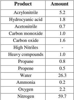
The outcoming flow (Tab.1.2) oversteps a cyclone to lose finer solid particles and to
reach a refrigerated water absorber (5°C) in which N2, COx and unreacted propene exit
and reach incineration. Ammonia is neutralized with sulphuric acid and it is separated as solid while nitriles remain dissolved. After tricky distillation and settling it is possible to separate water and organic phases; water solution is concentrated (97%) and refluxed, while the organic one, rich in ACN and HCN and containing also traces of acetone, acetaldehyde, propionaldehyde and acrolein, carries on to purification step in which the liquid flow undergoes a double distillation and vacuum ultra purification so that ACN reaches more than 94% purity grade.
Product Amount Acrylonitrile 5.2 Hydrocyanic acid 1.8 Acetonitrile 0.7 Carbon monoxide 1.0 Carbon oxide 1.6 High Nitriles - Heavy compounds 1.0 Propane 0.8 Propene 0.5 Water 26.3 Ammonia 0.2 Oxygen 2.2 Nitrogen 59.7
1.2
Propane Vs Propene
Only in the last decade came along the right conditions to take into account propane technology for ACN production. The development of new catalysts, correlated with new technologies of process along with the increase of propylene feedstock (up to 300 $/tons more expensive than saturated molecula), made alkane ammoxidation competitive on the market, especially if we consider that the price of olefin engraves on full cost in the amount of 67%. The need to substitute old plant along with the easily way to revamp the old ones made the challenge appealing.
In January 2007 Asahi Kasei Corporation started with a production based on propane technology and originated with the modification of an existing 70000ton/y ACN plant.
Some considerations are useful to understand this topic:
• Propane ammoxidation is a reaction composed of two theoretical steps:
o An endothermic process in which propane is dehydrogenated to
propene
o An exothermic process in which propene is ammoxidated to ACN
Esothermicity of ammoxidation is greater than endothermicity of dehydrogenation; the overall process is an exothermic auto-sustained reaction. To start from propene means splitting this reaction in two steps in which it is necessary to supply heat for propene production (i.e. in cracking technology, the actual main route of alkene yield) and to drain heat for ACN production, with a consequent energetic inefficiency.
• To Split a reaction in many steps means that we have the opportunity to tune
“easily” and thoroughly a catalyst so obtaining the better results which is possible to reach (right temperature, pressure, reactor, catalyst, precursors, contact time). Being able to condensate many stages and eventually to reach the single step means to strike a balance. In the first case high full costs reflect high production (high gain); in the latter one low production means
• An effective process for propane conversion to ACN has been developed over 30 years ago. It works at a higher temperature than the propene process and it needs the use of gas-phase precursors (causing problems in materials resistance and the increase of purification/recycling apparatus and costs). A strategic choice in ammoxidation to develop a successful replacing process is the conversion of an existing plan as long as the reactor conditions are the same.
• As far as the economical factor is concerned, many things have to be taken
into consideration: the reaction conditions, productivity and process costs. Propane works at a temperature 100-150°C higher than propene (due to an increase of homogeneous phase reactions), at a contact time 4-6 times longer, at lower conversion and selectivity, with a fixed investment 10-15% more expensive and with a feedstock 5-6 times cheaper. These parameters have some aftermaths such as higher ammonia consumption (due to the higher contact time, which leads to a higher oxidation to nitrogen) and more difficulties in reaction management (higher temperature and low ACN selectivity lead to higher deep oxidation products, which have strong effects on reaction heat and system temperature).
• Choosing the starting materials it is not the final goal: different technological
solutions have been developed to increase propane productivity and to enlarge the gain gap between alkane and alkene technologies.
The actual situation lies on the borderline defined with these two different processes, so that a little improvement in catalysts and processes or market changes may lead to prefer one feedstock or the other.
1.3
Ammoxidation
1.3.1 Ammoxidation of Hydrocarbons11
Ammoxidation is an oxidative process in which an Oxygen, Ammonia and Hydrocarbon mixture is selectively converted to nitrile and water; deep oxidation and unwanted nitriles are parallel and consecutive reaction products.
It is possible to feed every kind of hydrocarbon, even though alkanes, alkenes and aromatics are the main carbon source converted. It is possible to feed pure oxygen, but most commonly air is used.
R-CH3 + 1,5O2 + NH3 → R-C≡N + 3H2O (13)
The reaction is characterized by high exothermicity (AH° propene ammoxidation = -515KJ/mol) and increasing amount of moles (0,5) which makes the ammoxidation favourite at every temperature. The exothermic character of this class of reactions is increasing due to secondary products, such as carbon dioxide, which proceeds with higher energy release.
The ammoxidation reaction involves three consecutive steps:
• Hydrocarbon oxidation to form the intermediates on the active site; this is the
tricky step due to the hydrocarbon thermodynamic tendency to be over-oxidated to degradation and/or combustion products
• Nitrogen insertion; the activated ammonia on the catalytic site in presence of
oxygen can overcome combustion to produce N2 as main nitrogen-waste
product whereas the insertion of oxygen rather than nitrogen gives aldehyde in place of nitrile
• Oxidative dehydrogenation of the N-bonded species
The oxidative activation of the substrate is the main step, so it is crucial to design a system which is able to dehydrogenate with high efficiency and high selectivity in order to avoid over oxidation. This is why a catalyst for ammoxidation is usually also effective as a catalyst for dehydrogenation, but not the other way around.
1.3.2 Ammoxidation of propene8,10
Analyzing the alkene ammoxidation in literature almost every paper ascribes to propene.
The accepted general mechanism refers to the catalytic cycle (Fig.1.2) composed of three main steps:
• α-H abstraction (operated by Bi3+, Sb3+, Te4+)
• Olefin chemisorption and N/o insertion (over Mo6+, Sb5+)
• Lattice reoxidation (on redox couple Fe2+/Fe3+, Ce3+/Ce4+)
Fig. 1.2 Alkene ammoxidation Cycle
The cycle starts from the active site composed by two contiguous metal atoms in a
solid system: the first (M1) bonded to bridge oxygen and the second (M2) bonded with
oxygen by means of double bond. The site interacts with ammonia and forms an imino group (M2) after the expulsion of a molecule of water. Propene co-ordinates on M2 while Oxygen on M1 brakes the bridge bounding with the allylic hydrogen (α-H) to
radical hydrogen if the O-abstractor has a partial radical character too, conveyed by
some electron density present on the metal (M1). Insertion of nitrogen is now possible
and after a final oxidation ACN can leave the catalytic site along with a couple of water molecules. The reduced catalytic sites send vacancies to the reoxidation site, which is able to dissociate bimolecular oxygen in lattice oxygen (O2-), which moves toward the O-deficient metal and so neutralizes the vacancy.
The mechanism described above is possible in a solid system which is able to accommodate different metal cations arranged in complex bifunctional catalytic sites and in which oxygen, electron and anion vacancies are free to move in the lattice.
Multifunctionality which is needed in propene as well as in propane ammoxidation, can be achieved in two ways:
• Phase cooperation (antimonate): two different catalytic sites related to two different phases operate very close to each other, so that the molecules undergo the first reaction, desorb from the active site and then reach the second reaction to complete the transformation. Sometimes the phase boundary is not sharp-cut, but it is connected by a midway phase which settles the mismatch by means of nonstoichiometry.
• Element cooperation (multi metal molybdate): the sites which are able to
transform the hydrocarbon lie in the same phases so that the molecule does not need to desorb from a site to complete the ammoxidation, but it just needs to move from an element to another on the same lattice.
1.3.3 Catalysts for propene ammoxidation8-10
There are two classes of solid systems which are able to match with the properties listed above and actually used to perform propane ammoxidation:
• Multi metal molybdate (MMM) constituted of Mo Bi Fe Ni Co and
additivated with Cr, Mg, Rb, K, Cs, P, B, Ce, Sb and Mn, dispersed in silica (50%w/w) for fluid bed reactor application. The active site, as described in par. 1.2.2, is composed of Bi (M1) and Mo (M2) and can be described with
than to Mo, is active in α-H abstraction and Mo=O is responsible for NH-to-O substitution and NH insertion. The two electron pairs associated with two Bi atoms in Bi-O-Bi group or redox couple made by Fe, Ce, U and Cu are responsible for the O2 dissociation.
Fig. 1.3 Bi-Mo Catalytic Site of Bi2MoO6: O’ represents the Bi-oxygen active in α-H
abstraction and O’’ represents the oxygen substituted by nitrogen. Two lone pairs between Bi are the hypothetic site which is able to dissociate bimolecular oxygen for the solid state re-oxidation mechanism.
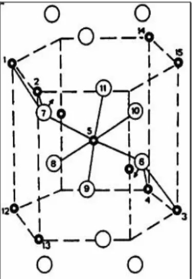
• Antimonate with rutile-type structure. The catalytic site is made of four metal antimonate cations: two bonded Sb5+ in the centre with two external Sb3+, as shown in Fig.1.4. Sb5+ activates and inserts ammonia as well as coordinating the olefin; the oxygen associated with the trivalent antimony is responsible for the α-H abstraction. In addition to antimony, at least one of the redox couple made by Fe, Ce, Cr and U is present to replenish the oxygen vacancy which had been created during the ammoxidation cycle.
Fig. 1.4 Antimony based catalytic site for propene ammoxidation. Starting from the oxidated site (in the square), the cycle represented in Fig. 1.2 is accurate: after the N-activation, propene is co-ordinated on Sb5+ and transformed in allylic intermediate by means of H-abstraction made by Sb3+; N-insertion is then operated by Sb5+ and after partial oxidation, ACN is desorbed and the catalytic site is re-oxidated.
1.3.4 Ammoxidation of propane
As already seen above, the activation of hydrocarbon is the crucial step in the ammoxidation process, especially the one in which alkane is converted due to the well known paraffin inertia.
The propene coordination, previously analyzed, starts with olefin allocation on the catalytic site thanks to the electron surplus due to the double bond which is not present in propane.
The key step in propane ammoxidation is the C-H bond dissociation, to form activated complex which is subjected to further H abstraction and propene formation. The activation proceeds via carbocation or carbanion formation by means of homolitical or eterolitical dissociation. Carbocation is more stable in central position (tertiary>secondary>primary) while, on the contrary, carbanion is more stable in pheripherical position (primary>secondary>tertiary). Propene is composed of 2 primary and 1 secondary carbons while isobutene is composed by 3 primary and 1
tertiary carbons, so that the reactivity of these probe molecules is associated with the carbon character. It seems reasonable to claim that to compare the conversion rate of propane and isobutene reflects the stability of the associated carbocation (CH3 -C+(CH3)-CH3 is more stable than CH3-CH+-CH3) and carbanion(CH3-CH2-CH2- is
more stable than CH3-CH(CH3)-CH2-). Conversion data are in favour of propane hence
the mechanism seems to occur via carbanion formation12.
In a two stage configuration of propane ammoxidation, hypothetically conducted in two different reactors, the reaction sequence is the following:
Propane → Propene → Acrylonitrile
It is reasonable to imagine that the same mechanism occurred in a single stage configuration, in which the transformation happened consecutively on two catalytic
sites, without an effective desorption mechanism after alkene formation13:
[Propane → Propene] desorption → re-adsorption [Propene → Acrylonitrile]
Another possible way of propane activation, proposed by Centi and co-workers14, was investigated by IR studies on probe molecules adsorbed on Vanadium antimonate.
Propane can undergo H- abstraction on Lewis acid site (represented by coordinatively
unsaturated vanadium) and subsequent nucleofilic oxygen attack. The obtained intermediate undergoes secondary H-abstraction and oxidation to form the propionate species. Oxidative dehydrogenation yields acrylate, which is the succeeding step in
ACN formation. In this mechanism the key step of H- abstraction can be disturbed by
ammonia adsorption on Lewis sites.
Catalysts active in propene ammoxidation are not able to convert effectively propane given their inability to abstract methylen hydrogen of paraffin in place of allylic one in olefin, mainly because of the higher C-H bond energy (89kcal/mol Vs 77 kcal/mol).
It is indeed necessary to implement the catalytic system with an oxidative enhancer
1.3.5 Catalysts for propane ammoxidation8
As in propylene ammoxidation, molybdate and rutile-type antimonate are effective in transformation of propane in acrylonitrile. Nowadays, the most active system is represented by Mo/V/Nb/Te/O, which is able to reach yield in ACN up to 62%. It has been developed by Mitsubishi Kasei and it is composed of two phases called M1 and M2 whose preparation is very difficult and relevant, along with the composition, the synthesis, the activation, the modality of doping and the nucleation/growth of the phases8.
Other catalysts have been developed by different Companies who claim very different reaction condition: propane rich and propane lean conditions, such as maximum conversion and low conversion with recycle, remain mostly unknown.
• Mo/V/Te/Nb/O: in the propane ammoxidation catalyst the metal cations are
arranged in more than one phase, mutually consistent in structure. Each phase is pure obtainable and tunable preparations are developed to reach
desired solid system composition. M1 phase (Mo7.8V1.2NbTe0.94O28.9
orthorhombic, in Fig1.5) is able to transform independently propane to
acrylonitrile with good performance but co-catalyst M2 phase
(Mo4.67V1.33Te1.82O19.82 pseudo-hexagonal) is required to promote the
unconverted-desorbed propene to ACN; catalyst is composed of 60% M1 phases and 40% M2 phases with traces of other phases. The general metals role is listed after:
o V is necessary to obtain the required crystalline structure, forming VO6 lattice network; it is the metal responsible for the alkane dehydrogenation; the lack of vanadium in M2 make the co-catalyst unable in alkane activation.
o Mo, like V, forms MoO6 lattice network; catalytically it provides to allylic co-ordination and nitrogen insertion.
o Te is located in the hexagonal ring and promotes the α-H abstraction
o Nb occupies the same position of Vanadium and improves the selectivity in ACN.
Fig. 1.5 M1 ammoxidation catalyst phase: O atoms are shown as brown spheres in the middle of each coloured four sided. In rectangular boxes are shown four active sites; looking at the upper one: the side lone sphere is Te4+, around central site composed bi the V4+0.8/Mo5+0.2 couple. Two opposite pitched sites are made by V5+0.5/Mo6+0.5 (bonded
out of the square with Mo6+) while the other two ones are made by Mo6+0.5/Mo5+0.5
(bonded out of the square with Mo6+ and Mo5+). The pentacoordinated site, made by four Mo6+ external site and one Mo5+, is occupied by Nb5+ and finally the site opposite to Te4+ bond site and between 4 Mo6+ sites is composed by V4+0.8/Mo5+0.2
• Bimetallic antimonate catalysts are solid systems typified by
nonstoichiometry, composed by Sb5+ and a metal in 3+ oxidation state (Cr3+)
or a couple of the same metal in different oxidation state (V4+/V5+, Fe2+/Fe3+,) in which the electro-neutrality is maintained by cation vacancies creation. V antimonate is one of the more investigated systems: a catalyst with a molar ratio equal to 1 gives a solid system in which cation-deficient structure is achieved with 0.04 cationic position unoccupied per O2- anion and electro neutrality is maintained by means of different V oxidation state (V0.92Sb0.92O4 is indeed V3+0.28V4+0.64Sb0.92O4). Preparation methods engrave on V(III) to V(IV) ratio so that it is possible to obtain system with V/Sb molar ratio equal to one in the V3+xV4+ySbzO4 range x=1 y=0 z=1 / x=0
y=0.89 z=0.89 (that is V3+1Sb1O4 to V4+0.89Sb0.89O4). However it is possible to obtain catalyst with V/Sb ratio different from 1:
o To keep unitary the coefficient of antimony, excess of Vanadium can
be inserted in the structure with a mechanism related to an
hypothetical insertion of V3+ atoms in the cation vacancies made on a
quasi- V4+0.89Sb0.89O4 high defective compound (the higher the V4+/V3+ ratio, the higher the cation vacancy amount) so that each V inserted is 3+ and, to maintain electro neutrality, three V4+ atoms
reduce to V3+: this way, starting from a mainly V4+ formula, a mainly
V3+ formula is reached. In the same way, in iron antimonate, the cation is placed in specific position and iron is reduced to evolve the rutile structure of FeSbO4 (FeIII) in tri-rutile superstructure FeSb2O6 (FeII).
o It is possible to increase the Sb to V ratio, but α or β Sb2O4 are formed in crystalline or amorphous forms
1.4
Rutile-type structure
1.4.1 Rutile StructureRutile refers to a structure composed by metal fluoride (Me2+) or metal oxide (d-incomplete transition and XIV group Me) in a tetragonal cell in which metal is bonded with six oxygen in octahedric coordination (Fig.1.7) and oxygen is in planar coordination with three metals (Fig.1.6).
Fig. 1.6 Rutile unit cell: in the centre and in the edge there are octahedric metals and on the other position the oxygens are placed in planar coordination
Fig. 1.7 Octahedric coordination of centred metals in rutile structure. Compared to Fig 1.6, the structure here is 90° rotated in the sheet plane and 90° perpendicularly.
It is possible to show another structural view considering a hexagonal coordination instead of tetragonal, as shown in Fig.1.8
Metal ions and oxygen hybridization cause distortion in the rutile structure:
• Highly charged vicinal ions repel each other and destabilize the structure inducing distortion.
• Oxygen bonded to 3 metal atoms reaches pure sp2 hybridization (from a quasi-sp2 one) so that a triangular planar configuration is achieved.
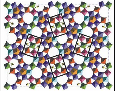
Fig. 1.8 HCP rutile lattice. Full circles in metal cation and empty circles represent oxygen ions.
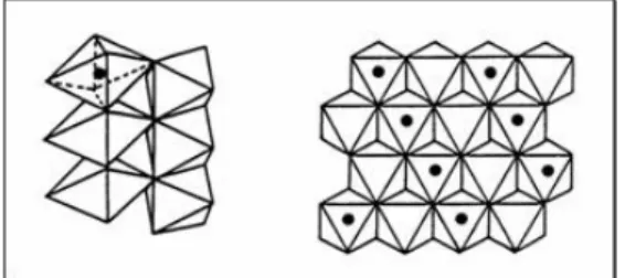
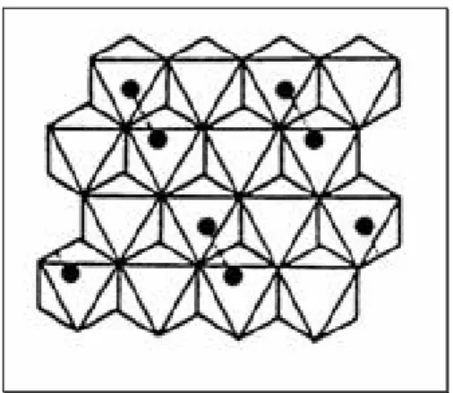
Octahedra are linked by vertex (c axe) and by edge (a and b axes, 90° rotated) to form infinite chain in c directions, as shown in Fig.1.8 and Fig.1.9. Considering all the octahedral site formed by oxygen (not shown in Fig. 1.9, but existing early in the empty spaces), half of the whole cavity is occupied by metal atoms (Fig.1.10).
Fig. 1.10 Octahedra edge-linked rotation and half-filled site arrangement.
Rutile systems can be classified as:
• Oxide (TiO2, SnO2)
• Rutile-type (FeSbO4, VSbO4, CrSbO4, AlSbO4, GaSbO4, CrNbO4, FeNbO4, RhVO4) and trirutile (NiSb2O6)
• Solid solution (VxTi1-xO4, VxSn1-xO4)
• Non stoichiometric solid solution (typical in Sb-rutile with the formation of
Sn oxides)
Trirutile structure (Me1Me2O6) mentioned above is a superstructure in which Me1
and Me2 are alternatively accommodated in an ultra ordered network (Fig.1.11).
Fig. 1.11 Rutile and tri-rutile structure 1.4.2 Rutile structure properties
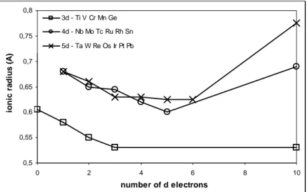
• Cationic Radius (Pauling) of cations (Me4+) which are able to get rutile structure are plotted versus the related number of d electrons (Fig.1.12); it is therefore clear that the existence range is 0.52<rc<0.78 Å. The cationic/anionic radius ratio (0.37<rc/ra<0.56 considering the previous data
and the oxygen radius in III coordination, 1.36 angstrom) is usually useful to predict the coordination geometry: 0.414 as minimum radius ratio in octahedric and 0.732 for cubic. The data are thus coherent but it is important to remember that this theory is applicable only for full ionic compound. This is a constraining factor for the rutile structure, in which covalent partial character is crucial in energetic stabilization. Moreover, the ionic model is unsuitable because of the prediction of four short and two long bonds, which is just the opposite of the real configuration. The loss in ionic character is mainly due to the cationic charge made by the oxygen.
0,5 0,55 0,6 0,65 0,7 0,75 0,8 0 2 4 6 8 10 number of d electrons io n ic r a d iu s ( A ) 3d - Ti V Cr Mn Ge 4d - Nb Mo Tc Ru Rh Sn 5d - Ta W Re Os Ir Pt Pb
Fig. 1.12 Ionic radiuses (angstrom) versus number of d electron 15. All data refer to charge 4+ and coordination VI.
• Electro-negativity, according to radius data, supports the pure ionic bond character mismatch: the electro-negativity difference between O2- and Me4+ describes the character so that values lower than 1,7 define the bond as covalent while values upper than 1,7 define the bond as ionic. As it is well known, it is wrong to consider “pure” a character only on that grounds but it is widely accepted to consider medium a character which is near the borderline value and pure a character clearly far from the borderline. As shown in Fig.1.13, rutile structure lies on the entire range of electro-negativity.
1 1,5 2 0 2 4 6 8 10 number of d electrons E le c tr o n e g a ti v it y D if fe re n c e 3d - Ti V Cr Mn Ge 4d - Nb Mo Tc Ru Rh Sn 5d - Ta W Re Os Ir Pt Pb
Fig. 1.13 Difference in electronegativity between metal and oxygen versus the number of d electron
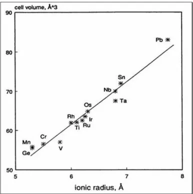
• Cell Volume: Rutile structure is able to accommodate cations with very
different size, condition which underline the elasticity of the lattice. As already said above, in some cases metal-metal interaction can occur and so the distortion of the cell happens: two ions accommodate on the same plane on “c” direction and attract one another (Fig.1.14). Cation interaction causes a lattice contraction along “c” parameters and a consequent “a” parameter stretching; these events modify the cell geometry but the volume remains the same. Vegard’s law is still valid in every rutile composition range (cell volume increases linearly with the ionic radius of the cation, as shown in Fig. 1.15).
Fig. 1.15 The cell volume value (cubic Angstrom) versus the ionic radius (Angstrom) shows linearity, as stated in Vegard’s law.
• Rutile-type structure solid solution can be theoretically formed as interstitial
or substitutional:
o Interstitial solid solution is formed by the insertion of a cation in an empty cavity. Many processes can compensate the positive excess of charge, such as cation vacancy formation, anion interstitial insertion or redox process on original lattice cation.
o Substitutional solid solution is formed by a substitution of an original
cation with another one. To maintain a lattice stability the substitute and the expelled metal have usually to be similar in radius and charge; however it is possible a larger cation insertion, which creates a lattice distortion, but the insertion of a differently charged cation is only possible if accompanied with redox reaction or vacancies creation, so that to maintain electro neutrality.
As far as the half octahedric empty sites are concerned, rutile-type interstitial solid solution has never been prepared, mainly because of the high instability created by the
positive ions inclusion. On the contrary, substitutional rutile can be easily synthesized provided that the general concept of similarity between the metal ions is observed in order to reach homogeneous solid solution; this means that similar cations may be un-soluble and very different metal may be miscible. It is impossible to make previsions and usually only a small range of composition may be obtained.
This structure gives a wide range of possible modifications which lead to different redox, electric and surface properties.
1.4.3 Heterogeneous ammoxidation catalyst design
The efficiency of a catalyst can be described with many parameters such as conversion, productivity and yield, but the power of a solid system in which a transformation of a molecule into another occurs, is mainly described with selectivity. Seven basic principles describe the features that a compound must have in order to drive efficiently a heterogeneous catalytic reaction.
• Lattice oxygen: catalytic mechanism can be shortly defined with the word
“coordination”. In gas phase oxidation, the gaseous oxygen is able to attack a molecule without hanging location preferences, so O2 is intrinsically unselective. The power of catalysis is due to the coordination activated on the reactants by the lattice. Reciprocal positions and the distance between the coordination site and the oxygen site allow the oxygen to attack the substrate only in specific position. Oxygen is present as O2- and it is exposed to gaseous phase to get in contact with the reductant; the vacation left by the reacted oxygen moves toward re-oxidation site and oxygen is replenished with bulk O2-.
• Metal-oxygen bond: the strength which keeps the oxygen bonded to the
catalysts is a key factor. A weak bond means that the oxygen is very reactive and available to different substrate sites, while, on the other hand, a hard bond highlights a low reactivity or even unreactivity. It is very important to tune the oxygen-lattice bond strength in order to obtain a mild condition
between the two extreme situations “selective/unreactive” and “reactive/unselective”.
• Redox properties: in order to define a reaction as “catalytic”, the reactive mechanism has to be repeated more than once on the catalytic site. The lack of Oxygen, occurred during the reaction on the catalytic surface, is replenished by bulk oxygen while the vacancy moves toward the reoxidation site, in which molecular oxygen is adsorbed from the gas phase, then it is cleaved and introduced in the solid system as O2-. The vacancy is thus neutralized and the redox catalytic cycle is now complete.
• Multifunctionality: the whole mechanism of substrate transformation is made
up in different steps: adsorption, activation, N-inserption and, oxidation. Different metals are involved in such reactions in different catalytic sites, so that multifunctionality is often synonymous of multimetallicity. Different metals are different elements with different atomic number (i.e. Bismuth molybdate composed by Bi3+ and Mo6+) or the same element with different oxidation state (i.e. antimonate catalyst made of Sb3+ and Sb5+)
• Site isolation: it is necessary to achieve selectivity, which can be obtained with spatial separation among the surface sites, usually the oxygen ones. The number of vicinal oxygens reflects the reaction stoichiometry achieved in the catalytic mechanism: less oxygen than necessary leads to a hydrocarbon activation without complete transformation; higher amount of vicinal oxygen can push the activated substrate to over-oxidation.
• Cooperation of phases: as already seen before, multifunctionality is reached
with the aim of placing different catalytic sites in one single phase or in more than one. The mechanism of substrate transformation starts from adsorption and activation; if the multifunctionality occurs in different phases, the intermediate has to move on the surface from a site to another, in adsorbed (or quasi-adsorbed) conditions. To reach effective cooperation the site has do be near and, consequently, the phases must be intimately linked; it means
that different phases must form a coherent interface, which is usually reached only in similar structures or by means of intermediate lattice.
2
EXPERIMENTAL
2.1
Catalysts
Rutile-type antimonates are catalysts which are active in ammoxidation of hydrocarbons. In order to increase the substrate activation properties of the catalyst, a secondary element (such as vanadium or others active in dehydrogenation) is often added to form a binary system. These elements are able to increase the conversion rate of olefins or to allow the activation of the paraffins.
2.1.1 Catalysts preparations
Many preparations are claimed to be active in the synthesis of such systems and the choice depends on many important factors, like the final product features and the scale applications (lab scale or industrial scale). Generally speaking, the main steps are the following:
• Raw material selection: antimony and the second component can be used in
different oxidation state and associated to different anions; preparation claimed to be active in rutile synthesis starts from Carbon oxides (Sb2O3, Sb2O5, V2O4, V2O5, Cr2O3,…) or from soluble salt (SbCl3, SbCl5, Cr (NO3)3, VO(acac2), SnCl4, NH4VO3…).
• Component mixing: there are basically two ways, a dry one (oxide mixing) and wet one (water solution). The aim of this step is to reach a homogenous intimate-contact mixture.
• Precursor preparation consists of evaporation of the solvent and/or redox
reactions.
• Thermic treatment involves phase changes and reactions necessary to obtain
rutile structure.
The dry way of catalyst preparation consists of oxide mixture made by graining or milling and subsequent heat treatment; typical preparation made by solid reaction is the formation of vanadium antimonate rutile. It is desirable to obtain a catalyst in this
way because of the easy operation, the absence of liquid reflue and the economic factor; the container and the balls have to be made by materials selected in order to avoid corrosion or element migrations. On the other hand it is difficult to control reaction parameters such as real temperature produced by the reaction itself, pressure impressed on grains by the spheres in the mill, influence of speed induced by the mill. As claimed by Berry et al., the operation described above on Sb2O3 and V2O5 is easily conducted, but very condition sensitive: the preparation consists of equimolar mixing and a very slow heating rate composed by (i) heating to 600°C in 12 hours, (ii) still 600°C for 12h, (iii) temperature increasing to 750°C in 6 hours and (iiii) isothermal treatment at 750°C for 24h. This reaction, performed in oxygen-free nitrogen, leads to
a monophasic vanadium-rich rutile phase (V1.05Sb0.95O4) and sublimation of
antimony(III) oxide; no reagents residue are observed. The same reaction made in
commercial nitrogen results in a rutile antimony-deficient phase and a α-Sb2O4 phase
formed by oxidation of antimony by molecular oxygen; in presence of oxygen, vanadium oxide is subjected to a redox reaction, due to the antimony which reduces
V2O5 to form the tetroxide. Oxygen excess in the gas phase leads to an initial antimony
oxidation to α-Sb2O4 which is unable to react with vanadium. In all preparation methods an excess of antimony leads to the formation of surplus antimony oxide phase while an excess of vanadium results in presence of V2O5 as unreacted reagent. 16. Solid state reaction of Chromium and antimony trioxides are described by Filipek at al. to obtain rutile phase in long-time thermic condition (from 500°C to 1000°C in almost 12 days)17.
The wet way consists of a suspension of Sb2O3 in water in which NH4VO3 is dissolved. After solvent evaporation the precursor is dried and calcined at 900K.
Starting from equimolar V and Sb, rutile phase and traces of α-Sb2O4 are obtained; an
excess of antimony leads to an increasing amount of antimony tetroxide18. Similar preparations are described by Cavani and co-workers starting from Antimony(III) oxide and Vanadium pentoxide pre-treated with hydrogen peroxide to obtain monoperoxovanadium cation (VO(O2)+); also in this case rutile phase is obtained19.
Another wet way consists of the dissolution of the soluble salt containing the metal to be incorporated into the structure (VCl3, SnCl4, SbCl3, SbCl5, Cr(NO3)3, Fe(NO3)3 and so on), in absolute ethanol and the subsequent drip in water buffered at pH 7. Separation, dryness and calcinations complete the synthesis.
2.1.2 Rutile Phase
As already said before, rutile phase occurs during the precursor calcination. Centi and co-workers claim that in vanadium antimony rutile phase, the cation redox reaction takes place in the 350-500°C range20. Cavani et al., studying the solid state reactions between different antimony oxides and vanadium pentoxide, observed the absence of rutile formation at 400°C calcination temperature, traces of SbVO4 at 500°C (using Sb2O3) and complete transformation to rutile phase at 600°C (using Sb2O3). At the latter temperature, rutile formation in Sb2O4 synthesis is detected in
small amount.19. To obtain rutile phase with good confidence, temperature has to keep
in the range of 700-800 °C. Temperatures above 800°C break the rutile lattice to form Carbon oxides more stable.
It is necessary to stress the relevance of the time needed for the rutile formation: intimate contact reached in wet way synthesis corresponds to an easy diffusion of a cation to another phase to give redox reaction. Solid state reactions are related to a spatial separation between the cations placed in different (although intimately mixed and grained) physically separated grains, so that the mutual diffusion needs a great deal of time and sometimes a higher temperature. Actually, in solid state reactions, the higher temperature holds on the order of days (24 hours or more) while in coprecipitation temperature holds on the order of hours (usually 3 hours).
Rutile phases are detectable and usually studied by means of X-ray spectroscopy and Raman spectroscopy:
• In X-ray spectroscopy the antimonate chromium and vanadium rutile lattice
cell shows four main lines around 28, 35, 54 and 68 2θ and minor line around 39, 41, 57, 61 and 64 2θ. As observed before, rutile structure owns a very flexible lattice, which is able to accommodate vacancies and excess of
cations by means of non-stoichiometry. This variation results in lines-shift: an expansion of the cell induces a shift of the lines to lower angles and the extent of the movement is different from line to line. Different cations incorporated in the rutile lattice may induce a variation in the crystallinity and in the crystal size; this effect is recognised in XRD spectroscopy observing the lines shape. Scherrer formula relates the crystal size to the peak width at half height:
B(2θ) = Kλ/Lcosθ
• Raman spectroscopy is a very useful technique, as it is easy and fast.
Unluckily the spectra collected are often of low quality, so sometimes they are difficult to be interpreted. It has often been noticed that an improvement in the crystals quality leads to a better peaks resolution. Three bands at about
760, 670, 540 cm-1 are typical of the rutile structure and a broad band placed
in the 800 – 900 cm-1 range is usually assigned to defects in the Sb-O-Sb chain.
2.1.3 Antimony oxides phases21-23
Antimony is a silvery lustrous grey metalloid, present in oxidation states III and V, found in nature mainly as the sulphide mineral stibnite (Sb2S3). Oxides formed by antimony, included often in oxidation catalysts preparation, are difficult to be studied because of the different existing stoichiometry and different polymorph. The active
phase in catalysis is the most stable oxide Sb2O4, but oxide described with the formula
Sb2O3, Sb2O5 and Sb6O13 may also be obtained.
• Sb2O3 may be found in two different allotropes, both stable at room
temperature: (i) cubic colourless senarmonite consists of dimeric units highly volatile which is able to sublimate above 775K; (ii) orthorhombic valentinite has a layered structure formed by chains hold together by weak Sb-O interactions. There is no evidence of differences in catalysts preparation between the two polymorphs. Volatility of senarmonite leads to use aqueous media in the oxidation reactions. Preparation of antimony trioxide is possible
by oxidation of Sb (or Sb2S3) in air or by hydrogenation of higher oxides In Raman spectroscopy, senarmonite shows a main peak around 261 cm-1 and
secondary remarkable peaks at 197 and 84 cm-1; Valentinite shows peaks at
140, 294, 223 and 502 cm-1.
• Sb2O5 is the other full antimony oxidation state oxide and there is no evidence for the existence of the anhydrous powder. It is possible to synthesize the pentoxide starting from lower oxides in drastic conditions. Preparation of pure Sb2O5 starting from Sb2O5*nH2O, is often claimed to be possible; the heat necessary for the water evaporation is enough for the partial dehydration coupled with the oxygen loss, with the consequent
formation of Sb6O13. Only two Raman bands have been recognized in
pentoxide at 502 and 620 cm-1.
• Sb2O4 is the main mixed valency oxide, made of equimolar proportion of Sb(III) and Sb(V) and it should be responsible for the catalytic activity in
oxidation. It is prepared via Sb2O3 oxidation (at temperature above 870K) or
via decomposition of higher oxide (upper than to 1000K). “α” orthorhombic (also known as cervantite) and “β” monoclinic allotropes are available, but the first one is the most common and it is prepared by Sb (or Sb2O3) oxidation at 873K or higher oxide decomposition at 1223K. Lower reduction temperature leads to β allotropes formation, also achievable from α one at 1233K in sealed tubes. Cervantite is observed by means of Raman
spectroscopy through bands at 200, 62, 43, 140 and 403 cm-1; β form shows
band at 212, 79 and 405 cm-1.
• Sb6O13 is the mixed oxide made by Sb(V) and Sb(III) in 2:1 ratio. It is made
by Sb2O5 decomposition at 973K or by Hydrogen peroxide oxidation and it
shows a Raman band on 470 cm-1 This oxide has a structure between Sb2O4
and Sb2O5.The formation of Sb2O4 is a thermal evolution of Sb2O5, as described by the following steps:
o Sb6O13 non-stoichiometric amorphous - Sb6O13 non-stoichiometric crystalline (977K)
o Sb6O13 non-stoichiometric crystalline - Sb6O13 (977 – 1026K)
o Sb6O13 – α-Sb2O4 (>1026K)
2.1.4 Rutile – antimony oxide phase cooperation
Once analysed the great properties of rutile as lattice host structure, his synthesis and the phase characteristics of the antimony oxide, some consideration are needed in order to understand the behaviour of the antimonate catalysts.
It is widely accepted that an excess of antimony in rutile catalysts is needed to form an antimony tetroxide phase, which is able to enhance ACN selectivity. This effect has
been discussed by Andersson and co-workers: SbVO4 is unselective in propane
ammoxidation to acrylonitrile while cervantite is not active in alkane conversion; as shown in Fig.2.1, the increase of Sb to V ratio up to 1, leads to a clear decrease in propane conversion and in propene selectivity with a clear increase in ACN selectivity.
Fig. 2.1 Catalytic properties of rutile with increasing of nominal Antimony amount. Moving from 50 to 33.3 (from Sb/V = 1/1 to Sb/V = 2/1), the increase in ACN selectivity is drastic; higher Sb quantity influences significantly the selectivity and affects negatively the activity.
In order to understand the behaviour of the phases inside the catalyst, has been made a comparison of the following solid systems:
• mixture of SbVO4 and α-Sb2O4 after co-calcination at 800°C, (b)
• SbVO4 after co-calcination with α-Sb2O4 and sub-sequent sieve separation (c)
• α-Sb2O4 after co-calcination with SbVO4 and sub-sequent sieve separation (d)
This study (Fig. 2.2) points out the effective activity and selectivity in ACN of (b) compared to (a), according to the phase cooperation theory mentioned above. The increase in selectivity of (c) in comparison to (a) is remarkable, which is understandable if an antimony cation migration has been considered; the mechanism of migration, on vanadium cations, is crucial to explain the activity loss and the selectivity improvement on the usually unselective antimony tetroxide (d).
Fig. 2.2 Comparison of the solid systems described above: (a) pure SbVO4, (b)
mixture of SbVO4 and α-Sb2O4 after co-calcination at 800°C, (c) SbVO4 after
co-calcination with α-Sb2O4 and sub-sequent sieve separation, (d) -Sb2O4 after
co-calcination with SbVO4 and subsequent sieve separation.
2.1.5 Synthesis
Chromium antimonate has been synthesized with two different preparation methods:
• Co-precipitation, developed for preparation of SnO2 based systems by
Rhodia24: different weights of starting material (different soluble salt have been tested) have been calculated to obtain 10g of the desired Sb/Cr ratio.
SbCl5 (or i.e. SbCl3) and the other cation (Cr(NO3)3, Ga(NO3)3) are dissolved in absolute ethanol (usually 100mL of solvent are used); the first gives a pale yellow solution which becomes transparent and Cr3+ salt gives an intense blue mixture. Vigorous stirring has been kept for 15 minutes, at room temperature, to guarantee sufficient homogeneity of the solution. The mixture is then dropped in 100mL of water solution buffered with ammonium acetate (10%w/w) and kept at pH 7±0.2 by means of ammonia aqueous solution (10% w/w). After its separation from the supernatant, the solid has been washed 3 times with distilled water. The precursor is then dried at 120°C for 12 hours and calcined in air at 700°C for 3 hours. A crucial step of this preparation is the managing and accurately weighting the antimony chloride for its very tendency to hydrolyze, also with air moisture, to give gaseous hydrochloric acid and a white solid.
• Slurry, in 100mL of the water solution of Cr(NO3)3, or Ga(NO3)3, antimony
trioxide is kept in suspension by stirring at room temperature. After 15 minutes mixing, the solution is dried in rotavapor at 70°C and low pressure, then it is calcined in air. Varying time and temperature of the heat treatment allows obtaining different solid systems.
• High-energy milling is an easy technique already available to prepare
vanadium antimonate: the oxides of the cation (Sb2O3 or Sb2O5 and Cr2O3) are weighed and premixed in ethanol to ensure good homogeneity of the sample. After the liquid removal (3 hours at 120°C), the solid mixture is milled for the time needed to complete the solid-state reaction. The milled powder is then calcined for 3 hours at 700°C. In our case carborum tungstenate balls and container were used to avoid contamination or corrosion. Raman analyses of these samples did not point out considerable rutile bands and for this reason no test in ammoxidation has been performed. Further investigations are needed to understand the solid state reaction mechanism in rutile synthesis.
2.1.6 Catalysts characterization
The catalysts prepared with the methods described above are characterized with Raman spectroscopy, EDX probe, XRD spectroscopy, XPS, BET and AAS analysis.
• Raman Spectroscopy analyses are performed on a Renishaw 1000, with
confocal microscope confocal Leika DMLM (zoom 5X, 20X e 50X) coupled with a CCD camera. Excitement is made by green Argon at 514nm. The
instrument works in reflectivity within an area of 1 µm2 (considering a 50X
zoom) and 2 µm deep, so Raman spectroscopy is considered a technique for superficial investigation. Raman analysis is fast, in the order of minutes, very punctual and non invasive (usually non destructive, but sometimes bonds rupture occurs due to the high energy of the light source).
• EDX probe INCA Oxford mod 350 SEM Zeiss. Evo 50: the sample is
analyzed in powder or tablets form. During the analysis it is possible to collect SEM images of the catalyst.
• XRD diffraction analysis are conducted on an automatic powder
difractometer Phillips X’ Pert 9/29 with Bragg Brentano geometry, using Cu Kα (λ= 1,5416 Å) radiation and 1,5kw power. Analysis are performed in the range of 5° - 90° (2θ) with 0,02° (2θ) steps of 40 seconds each. Inorganic phase searching is based on Hanawalt on PDF-2 (Powder Diffraction File, ICDD) data. Quantitative analysis and structural data are calculated by means of GSAS software (Generalized System Analysis System). Scherrer formula is used for particle size estimation.
• XPS analysis are conducted in ultra high vacuum at 2x10⁻⁹ Torr, 200kV in “Survey” modality (surface atomic concentrations) and “Multi” modality (signals shape). The analysis works within an area of about 0,5mm2 and 10nm depth.
• BET measurements are made on a Carlo Erba Sorpty 1750 instrument, using
and nitrogen pulses at ca 77K (by means of liquid nitrogen). The pressure is measured during the pulse and gives indication of the monolayer formation; the number of pulses indicates the amount of nitrogen adsorbed as well as the area covered by the molecules.
• ICP-AAS: the sample is dissolved in TFM and hydrochloric acid by means
of a Milestone Ethos1 microwave (power around 1500W and at 220°C). Analysis are performed on an ICP PERKIN ELMER “OPTIMA 4300∆V”.
2.2
Catalytic tests
2.2.1 PlantIn Fig.2.3 it is shown the plant employed in gas phase ammoxidation of propane and propene.
Fig. 2.3 Schematic representation of the gas phase ammoxidation plant
Gas flows are measured by means of Mass Flow Meter (MFM) and are mixed joining together the exit pipes. MFMs are reliable in a fixed range, so the values set around the lower borderline lead to instability of the flow. V1+M1 and V2+M2 are two separated lines useful to spill out part of the reaction stream in order to decrease the total flow. That way it is possible to reach a lower flow than the MFM range or to change the stream (therefore the contact time) during the reaction. The feed line and an air line enter in a 4-way valve (V4) from which two lines come out: one headed to the reactor and the other to the gaschromatograph (GC). In one position of the valve the reaction feed goes to the analysis system while air passes through the reactor; in the
other position the reactant reaches the reactor and the air goes to the (GC). In the first case it is possible to maintain the reactor hot and the catalyst in air environment while the feed undergoes analysis. This is crucial because an oxide kept at high temperature in oxygen-free atmosphere may undergo to irreversible surface modifications and therefore lose the lattice oxygen. In the second case the feed runs to the reactor while air cleans the analysis system lines. V4 is important for the reaction safety because, if some problems occur and a security arrange is necessary, an easy and immediate valve switching quenches the reactor and puts the plant in safe conditions.
Following the analysis line, M4 is useful to waste part of the flow (like M1 and M2): little pressure is necessary to allow the flow feed the GC, but overpressure is unwanted. To handle the pressure of the GC, M4 is adjusted.
The reactor line crosses V5, a three way valve which is able to direct the flow to a soap flow meter (F1) for the flow measurement. That way the reactor has not been crossed by reaction feed, or by other gases so it is fully isolated. This is a way to interrupt the reaction (like in the case already seen with V4), but in this situation the catalyst has not been crossed by air so that it may undergo reduction and surface modification.
The flow that passes through the reactor is subjected to friction loss, which is nearly absent in the soap flow meter. The measured and the real flows are different; we claim that the over pressure induced by the friction loss is negligible so that measured and real flows may be considered equals; it is not possible to measure the stream in the outflow because of the condensation of some products due to the lower temperature and the crossing of the soap.
The flow passes through the reactor and it is parted: a portion reaches the GC, dosed by M5, and the other goes to vent.
Each flow coming out bubbles in a water basic absorber so that products and acids are stopped by condensation or neutralization. Only gases such as carbon oxides, nitrogen, helium, unreacted oxygen and negligible amount of hydrocarbon are released to atmosphere.
2.2.2 Analysis
The plant is integrated with an on-line GC AGILENT 7890 A and an at-line GC able to separate propane and propene
The analysis of the flows is carried on with 3 columns:
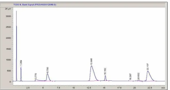
• Col 1 leads to a chromatogram like the one shown in Fig.2.4, in which the first peak is formed by O2, N2 and CO while the others are related to CO2 (1.3’), NH3 (3.8’), Propane/Propene (5.7’), H2O (12.9’), HCN (15.1’), Acrolein (19.3’), AcCN (20.5’) and ACN (22.1’).
Fig. 2.4 Gas-Chromatogram obtained with the column 1; peaks are resolved except for the ammonia one(3.7s), which shows a long tail on which propene peak is formed.
• Col 2 is a pre-separation column, in which O2, N2 and CO pass un-held at the
same time.
• Col 3 makes the separation of the previously un-separated peaks eluted in Col 2 (Fig.2.5): O2 (2.4’), N2 (3.2’) and CO (6.6’).
Fig. 2.5 Gas-Chromatogram obtained on Column 3: Nitrogen (3.2’) comes out as oxygen shoulder.
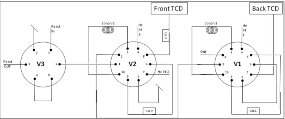
The sample insertion in the GC occurs by means of pneumatic valves handled with the instrument software. Three valves are required, as shown in Fig. 2.6.
Fig. 2.6 The sampling valves needed to feed the columns.
V3 is the first-six-way-valve in which the flow coming from the line before the reactor (react in) and the flow coming out of the reactor (react out) are selected to be sent to the other valves or to be joined to the vent line.
V2 is a ten-way-valve in which the flow selected in V3 and two separated flows of Helium enter and then may be connected to a loop (loop V2), to the vent line or to the column 2. The last one is then directed to the vent line, to the other valve or to the column 3. In the “off” position, the flow coming from V3 crosses the loop and reaches V1; at the same time an He feed washes the column 2 counter-current and goes to vent
while the other He feed passes through column 3/TCD. In the “on” position the flow coming from V3 is joined to the V1 line directly and a helium line crosses the loop and reaches the column 2, the column 3 and eventually the detector. The other He line goes to vent. This system is useful because in column 3 it is possible to separate oxygen, nitrogen and carbon monoxide, but at the same time the column filler can not get in contact with ammonia. In fact, the gas feed injected by loop V2 is pre-separated in column 2, in which O2, N2 and CO exit all together not restrained (retention time is indeed dead column time) and go to column 3; after these substances retention time, the valve switches so that gases not eluted have been washed away by an helium flow. This way Oxygen, nitrogen and carbon monoxide in the column 3 have been separated and reach the detector TCD front.
In V1 the flow coming from the second valve and helium are fed; a loop and the column 1 line may be joined with the inner line. Gases coming out from column1 and the loop may be connected to the back detector or to the vent line. In the “off” position the feed crosses the loop while the column and TCD have been crossed by Helium. In the “on” position the loop V3 is washed by helium and the content goes to back detector after having been separated in column 3.
The normal position of valves 1 and 2 is “off”, which means that loop is loading and helium is cleaning the columns and the detectors. When analysis starts, the valves automatically turn in “on” position and the sample reaches the columns. After ca. 3 minutes valve 2 repositions itself on “off” position, as well as valve 1 at the end of the analysis after 25 minutes.
In ammoxidation of propene , no other device is required.
In propane ammoxidation, however, along with unreacted alkane, propene is present in reacted flow. In the analysis system described above, propane and propene are not separated, so they have been revealed at the same elution time (same peak). The quantification of propane and that of propene are operated on another instrument equipped with a Flame Conductivity Detector (FID) by means of sample injection with syringe, drown by a septa inserted in the line coming out of the reactor and directed to vent. The response factors of propane and propene are the same both in TCD and in