The contents of the following works of the author of this PhD thesis have
been taken as a reference point for the writing of this thesis:
1. G. Ivetic, A. Lanciotti, Finite Element analysis of Laser Shock Peening
of Aluminium alloy 7050-T7451 thick plates, submitted to the 2
ndInternational Congress on Laser Peening, San Francisco, USA, April
18-21, 2010.
2. G. Ivetic, 3-D FEM Analysis of Laser Shock Peening of Aluminium Alloy
2024-T351 Thin Sheets, Accepted for publishing in Surface Engineering,
July 26, 2009.
3. G. Ivetic, A. Lanciotti, C. Polese, Electric Strain Gauge Measurement
of Residual Stresses in Welded Panels, Journal of Strain Analysis for
Engineering Design, Vol. 44-1, 2009, 117-126.
4. G. Ivetic, A. Lanciotti, C. Polese, Analysis of Out-of-plane Welding
Deformations, 19th Italian Abaqus Regional Users’ Meeting, Milan,
Italy, November 5-7, 2008.
esten-Table B1. Temperature dependant thermal and mechanical properties
of 2219-T851
Temperature
Young’s
Modu-lus
Thermal
Con-ductivity
Specific Heat
(
◦C)
(MPa)
(W/m
◦C)
(kJ/kg
◦C)
20
70000
155
0.9
80
68000
170
0.95
100
66000
175
0.98
140
64000
180
1
180
61000
185
1.02
220
58000
190
1.05
240
56000
195
1.07
280
52000
205
1.1
300
49000
210
1.12
320
47000
215
1.15
380
40000
225
1.18
400
32000
230
1.2
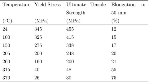
Table B2. Temperature dependent mechanical properties for 2219-T851
Temperature Yield Stress
Ultimate Tensile
Strength
Elongation
in
50 mm
(
◦C)
(MPa)
(MPa)
(%)
24
345
455
12
100
325
415
15
150
275
338
17
205
200
248
20
260
160
200
21
315
40
48
55
370
26
30
75
Table B3. Temperature dependent mechanical properties for 2219 FSW
weld bead
Temperature Yield Stress
Ultimate Tensile
Strength
Elongation
in
50 mm
(
◦C)
(MPa)
(MPa)
(%)
24
165
270
12
100
155
258
15
150
131
211
17
205
95
154
20
260
76
124
21
315
19
30
55
370
12
18
75
Laser Shock Peening literature overview is presented in this appendix
and it is adapted from reference [59], where the most important works
considering LSP from the ’60s to today are summarized. The literature
overview is integrated with the most recent works regarding LSP.
The appendix is divided in three tables, covering the historic
develop-ment of the LSP, the most important works regarding LSP as a method
for introducing residual stresses in structures for improvement of fatigue
properties and finally, FEM analyses of LSP.
Table C1. Laser Shock Peening literature overview - historic
develop-ment of the process
Processed materials/ targets Confining/ absorbing layers or environment Lasers and beam proper-ties
Novel features, observed phenomena and comments
Ref.
Generation of momentum on solid targets by recoil pressure of laser evaporated mate-rials is proposed, possible applications be-ing the acceleration of bodies and genera-tion of ultrasound
[103] (1963)
Duraluminium Black coating (optionally)
Ruby ≈500µs A pressure pulse corresponding to laser pulse and not explainable by light pressure was observed; black coating enhanced the pressure [50] (1963) Cu, Al, Pb, Ta, steel, brass, porce-lain
Vacuum 50 ns, 0.32 J Momentum achieved by target was mea-sured by piezoelectric transducer; mo-ments up to 0.36 dyn s were recorded ≈4 decades more that the momentum of light
[104] (1964) Be, C (graphite), Al, Zn, Ag, W Vacuum Ruby, 7.5 ns, up to ≈ 4x10¹⁰ W/cm2 spot 3.4-29 cm2
Momentum achieved by target was mea-sured by a pendulum; , the momentum has maximum at laser energy density ≈ 1GW/cm2, depending on target [105] (1966) Al and Cu (films 0.1152µm) Transparent material (not specified) Q-switched 20 ns, 5 J
Damage of targets observed; pressures measured by piezoelectric transducer reached tens of kbar; pressure pulse duration was 100 ns
[106] (1968)
Ta, Ag, Sn, Si, Pb, V, Hf, Zn, 6061-T6, AISI 304 Vacuum (for avoiding breakdown) Nd:glass, 1.06 µm, 60 ns, 60 J, 1 GW
Momentum achieved by target was mea-sured by a pendulum; estimated shock pressure 736 kbar depending on target ma-terial [107] (1968) Al (0.5µm film on back side of a quartz plate) Quartz (6 mm) Ruby, 12 ns, 7 J, spot 6mm
Measurements of laser pulse induced pres-sure transients by quartz gauge, epoxy bonded to the Al film; maximum pressure of 34 kbar was recorded; pressure pulse was longer than the laser pulse; experiments were performed in vacuum chamber
[51] (1970)
Processed materials/ targets Confining/ absorbing layers or environment Lasers and beam proper-ties
Novel features, observed phenomena and comments Ref. Ni, V (50µm foils) ? Ruby, 694.3 nm, spot 3mm
Laser irradiation generated crystal lattice vacancies in targets, probably due to shock waves; no ablation crater, but some surface damage and slight depression of the foils were observed [108] (1971) Al (100µm layer on glass) Glass (5.1 mm) Ruby, up to 4 J
Laser irradiation caused detonation of vari-ous explosives in contact with the Al layer; the shock strength of these explosives was 715 kbar [109] (1971) 7075 T73 and 7075 T6 Al al-loys Glass (1 mm) with Na2SiO3 contact layer Nd:glass, 32 ns, up to 72 J/cm2
The 0.2% offset yield strengths of mate-rials were increased up to 30% over un-shocked values; microstructural analyses showed that laser shocking induced a tan-gled dislocation substructure similar to ex-plosively shocked aluminium
[110] (1972) 1100-0 Al alloy (0.76 mm) Silicone adhe-sive (25µm) or Duco cement (63µm) Nd:glass, ≈50 ns, up to 91 J/cm2
Recorded by piezoelectric gauge pressures reached 7.9 kbar (Duco cement layer on surface); pressure on coated targets was over 10 times larger than on bare targets; pressure dependence on laser fluence pre-sented; the experiments were performed in vacuum [111] (1972) 2024 T3 Al al-loy Air? Ruby, 694 nm, 1 ms, 4 J, spot 9.53 mm
Surroundings of a small hole (3.175 mm di-ameter) were treated by laser pulse; fatigue life of the treated workpiece was enhanced; fatigue life improvement corresponded to compressive stress 55.2MN/m2 [112] (1973) Stainless steel (0.63 and 0.76 mm), Al (0.41 mm) Plexiglass or fused silica/Al (1µm) + adhe-sive or Mylar film Nd:glass, 25-55 ns, up to 1.7 GW/cm2
Permanent local deformation was observed in the targets; estimated specific impulse > 3000 dyns/cm2 and pressure up to 30
kbar; deformation occurs in some µs (de-termined by a probe beam); discussion of deformation mechanism on the basis of elastic/plastic wave propagation in the tar-gets presented; the experiments were per-formed in vacuum
[113] (1973)
Processed materials/ targets Confining/ absorbing layers or environment Lasers and beam proper-ties
Novel features, observed phenomena and comments Ref. Fe-3 wt% Si alloy (rolled, 92.7-300µm) Fe (14µm -for pressure measurement) Fused silica (3 mm) Nd:glass, 20-30 ns, up to 31.2 J/cm2
Peak pressures at backside of samples up to 56.6 kbar (Fe, 14µm) recorded; pressure absorption in samples compared with cal-culations [114] (1974) Plexiglass (3.2-12.7 mm), 1100-series Al (0.17 mm), 6061-T6 Al (1 mm) Water droplet and/or black paint Nd:glass, 1.06 µm, 1.5 and ≈30 ns, spot 2.8 mm, up to 500 J/cm2
Target’s surface damage and effects of confining/absorbing layers on induced by laser pressure investigated; greatest pres-sure (3.8 kbar peak - 1mmAl, 10 J/cm2)
were observed in case of water confinement in conjunction with black paint absorber
[115] (1974)
B, C, Mg, Al, Si, Ti, Cr, Mn, Fe, Co, Ni, Cu, Zn, Ge, Zr, Mo, Ag, In, Sn, Sb, Pt, Au, Pb, Bi, (25 - 1100 µm foils or films on glass) Borosilicate glass (5.2 mm) Ruby, 5 J, up to 14 kJ/cm2
Target films were confined between two glass plates (5.2 and 1.9 mm); pressures up to 20 kbar were recorded, the pressure depend nearly linearly on laser fluence
[116] (1974)
A theory of blow-off vapour-generated shock fracture of brittle and ductile ma-terials is presented; the theory considers the degree of ionization of the plasma and shock attenuation
[117] (1976)
Table C2. Laser Shock Peening literature overview - residual stresses
and fatigue
Processed materials/ targets Confining/ absorbing layers or environment Lasers and beam proper-tiesNovel features, observed phenomena and comments Ref. 5086 H32 and 6061-T6 Al alloys (welded zones) Fused quartz (2mm on one side of the tar-get or 3mm on both sides) Nd:glass, 25 and 185 ns, up to 2.16x10⁹W/cm2; irradiation also from both sides of the sample (also simultane-ously and of overlapped areas)
After laser shocking the tensile yield strength of 5086-H32 was raised to the bulk level and the yield strength of 6061-T6 was raised midway between the welded and bulk levels; the increases in ultimate tensile strength and hardness were smaller than the increases in the yield strength; the microstroctures after shocking showed heavy dislocation tangles typical of cold working; melted surface layer thickness was 5-50µm; shrinkage cracks in melted layer were observed
[118] (1976)
Aluminium al-loys, foils, and films
Fused quartz, water
Nd:glass A short review (19 refs., 5 figs) on LSP techniques and results; quartz overlay pro-vides up to 40% higher peak pressure than water overlay; for ≈30 ns laser pulses the pressure pulse was up to ≈7 times longer than the laser pulse; yield strength of weld zones in 5086 H32 and 6061 T6 Al-alloys was increased after laser treatment to the bulk value [119] (1976) 7075 T73, 7075 T6, 2024 T3, 2024 T8, 5086 H32, 6061 T6, AISI 304, Fe-3 wt% Si, Ti- and TiV-alloys
Water, quartz, plastic
Nd:glass, 22 and ≈40 ns
LSP resulted in increased surface hard-ness, yield and fatigue strength of homo-geneous samples, weld zones and fastened joint specimens; multiple shock treatment (five shocks) was advantageous for AISI 304 (surface hardness increased for 40%); results of calculation of transient temper-atures and pressures by LILA code pre-sented - Zn coating on Al target should en-hance both temperature and pressure; mi-crostructure photos of unshocked/shocked aluminium alloys and steels presented
[120] (1979)
Processed materials/ targets Confining/ absorbing layers or environment Lasers and beam proper-ties
Novel features, observed phenomena and comments Ref. 2024-T351, 2024-T851, 7075-T73, 2024-T351, 7075-T651 (0.9 - 3 mm) Quartz or water/ black paint
Laser shocking increased considerably hardness of 2024-T351, tensile strength of 7075-T73, 2024-T351 and fatigue life of 7075-T6; irradiation of samples from both sides simultaneously gives better results
[121] (1979) 2024-T3 (6,4 mm) Water, quartz, acrylic (both 6.4 mm)/metal primer+black paint Nd:glass, 30 ns, up to 12x109 W/cm2, spot 1.1-1.6 mm, also annular beam
One and two-sided, simultaneous and subsequent, also with “momentum trap” shock processing compared; hole surround-ings processed by annular beam as well; best results were achieved by simultane-ous two - sided shocking, but the use of momentum trap provided nearly the same results; fatigue life of plates with hole was increased up to 40 times due to shock pro-cessing; fractographs and fracture propaga-tion schemes presented
[73] (1983)
35CD4 stain-less steel
3 and 30 ns A 1D-analytical model for calculation the thickness of plastically affected zone (PAZ) in laser-shocked half-plane, solid presented; residual stress profile and plasti-cally affected zone thickness presented for laser shocked 35CD4 alloy; the simulation yielded twice deeper PAZ than observed in the experiment [122] (1988) [87] (1991) 18 Ni (250) maraging steel (4.15 mm), also weld zones Water (≈3.5 mm)/ black paint (≈0.1 mm) Nd:YAG, 1.06 µm, 100 ps, 20 mJ, 8 Hz, spot ≈0.1 mm, ∼1012W/cm2, scanned beam
LSP results have been compared with shot peening (20 min with chopped steel fibres of 0.5 mm diameter and of 1.5mm length in a 0.54 MPa air, 100% coverage) results; the modified depth (raised hardness and compressive residual stresses) were 0.05 and 0.25mm for LSP and SP, respectively, the residual stresses in weldments - 416 and 893MPa, and the fatigue strength of welded samples (2x10⁶cycles) 380 and 587
MPa, respectively
[123] (1990)
Processed materials/ targets Confining/ absorbing layers or environment Lasers and beam proper-ties
Novel features, observed phenomena and comments Ref. 18 Ni (250) maraging steel Water (≈3.5 mm)/ black paint (≈0.1 mm) Nd:YAG, 1.06 µm, 150 ps, 8 Hz, spot ≈0.1 mm, scanning with shot over-lapping
Shock processing increased the hardness and fatigue strength (17%) of weldments; plastically affected depth was ≈50 µm, con-taining reverted austenite phase and in-creased dislocation density (according to TEM studies) [124] (1990) 35CD4, XC38 Glass or water (2 mm)/ black paint Nd:glass, 1.06 µm, 2.5, 3, 25 and 30 ns (Gaussian or asymmetri-cal), spot 8 mm, up to 70 GW/cm2
Residual stress distribution vs. depth for irradiance power densities 1-70 GW/cm2
presented; repeated shocks increase the plastically affected depth but decrease the surface stress (1-6 laser pulses); laser peen-ing increased fatigue strength 40% and did not affect the surface roughness
[125] (1991) 7075-T6, 2024-T3, and 5456 Al alloys; 1026 and 4340 steels Mostly water/ black paint 1.06 µm,≈20 ns, spot 5-10mm
Data about residual stress distribution, fa-tigue life and surface hardness of laser-shocked, samples presented
[126] (1991) [127] (1992) [128] (1992) AISI 316L No/black paint 0.6 ns, 80 J, spot 7.2 mm, 0.3 TW/cm2, 18 GPa
LP was compared with explosive shock treatment (1-2 GPa, 1 µs); the formed mi-crostructures and hardness profiles were quite similar; surface mirohardness was raised from 180 HV to ∼300 HV in both cases, the surface hardness of LP processed samples was somewhat higher (345 HV) but the hardness decrease was more faster than in explosively treated material; the residual stresses in both cases were stable during a whole cycling of a plastic fatigue test (constant plastic strain rate 2x10⁻³ s−1), contrary to SP processed material
[129] (1992)
Processed materials/ targets Confining/ absorbing layers or environment Lasers and beam proper-ties
Novel features, observed phenomena and comments Ref. 7075-T7351 Water/Al self-adhesive foil (0.1 mm) Nd:glass,∼25 ns, spot 0.5-1 mm (square and circular), 1-7GW/cm2
Residual stress and hardness profiles, and fatigue resistance were determined for both laser shocked and shot peened (0.6mm steel beads,Almen intensity F20-23A/F23-27A, coverage rate 125%) samples; LSP was found to provide greater improve-ment of fatigue limit than SP; combined SP+LSP treatment was found to be benefi-cial; the experimental results are compared with analytical and numerical (SHYLAC 1D) models predictions
[130] (1995)
0.55%C steel Water or glass Nd:glass, 1.06 µm, 25 ns, spot 5mm (circle and square), 1.7-10 GW/cm2, 25% overlap
Residual compressive stresses down to depth of 1.1 mm exceeding up to -350 MPa on surface were formed; shocked surface de-pression was up to 7 µm; the surface hard-ness was not modified; the central stress drop was present in case of circular laser spot, but was absent in case of square spot
[67] (1995)
SUS304 (austenitic, 20 mm)
Air and wa-ter (specimen were immersed into water) Cu-vapour (511 nm) and Nd:YAG (532 nm), 5-50 ns, spot 0.2-1.1 mm, 75-375 J/cm2, 15-75 TW/m2
The specimens were laser peened using scanned beam, coverage 500-8000%; sur-face compressive residual stresses of 200-400MPa were built up; the depth of com-pressive residual stresses was over 200 µm; the peened sample’s surface was oxidized down to a depth of 3 µm; high-speed pho-tographs of plasma radiation in air and in water presented - in water the plasma lasted ∼10 ns; plasma expansion velocity in water was ∼1500 m/s, in air ∼7700 m/s
[131] (1995) A356-T6, Al12Si-T6, 7075-T7351 (Al alloys) Water (2- 5 mm) Nd:glass, 1.06 µm, 25 ns (Gaussian), spot 5-12 mm, 1-8 GW/cm2; up to four im-pacts (square, ellipse or cir-cle, up to 67%
Laser shock-induced residual compressive stress field extended to depth more than 1 mm, surface hardening was limited to +10% of the initial value, half of the increase achievable by conventional SP (+22%); in contrast to SP, laser shocking did not affect the surface roughness of the materials; fatigue life (107 cycle tests) of
lasershocked specimen exceeded these of [56] (1996)
Processed materials/ targets Confining/ absorbing layers or environment Lasers and beam proper-ties
Novel features, observed phenomena and comments Ref. 55C1 steel (10 mm) Glass/PMn treated sur-face Nd:glass, 1014 W/m2, 6 GPa
Quenched by 5 kW CO2 laser in Ar
at-mosphere sample was shocked by Nd:glass laser; a 50% increase of surface stresses (-280 to -420 MPa) and a suppression of the tensile peak at depth of ∼500 µm was ob-served; the physical processes and analyti-cal modelling of LSP are reviewed
[132] (1996)
SUS304 Water 2ω-Nd:YAG, 532 nm, 5 ns, 10 Hz, spot 0.75mm, Cu-vapour, 511 nm, 60 ns, 4 kHz, spot 0.5mm
Relatively large pulse frequencies were used resulting in large shot coverage fac-tors of 500-8000%; peak power densities ranged 15-75 TW/cm2; residual
compres-sive stresses exceeding 400 MPa were de-veloped over 100 µm in depth; in case of 60 ns, 4 kHz laser irradiation, a 10 µm sur-face layer exhibited tensile stresses
[133] (1996) SUS304, In-conel 600 Water 2ω-Nd:YAG, spot 0.75 mm, 230 kJ/m2, 50 TW/m2
Compressive residual stresses over 100 MPa were created by laser shocking
[134] (1996) Al (200 µm foil), AISI 316L (200 and 500 µm), 55C1 (360 µm and notched samples), 7075-T7351 (1.6 mm) Water/Al-based paint or adhesive (90-140 µm) Up to 8.5 GW/cm2, spot sizes 1 and 6 mm
VISAR-measurements of back free veloc-ities (BFV) behind foil targets (up to 500 m/s at ≈6 GPa) agreed well with SHYLAC-simulations; paint/adhesive lay-ers enhanced the shock pressure for ≈50%; HEL of materials was determined from BFV at elastic-plastic inflection point (1.2 σyfor 7075; 2.3 σyfor 316L and 55C1);
us-ing small impacts (1 mm, 25% overlap) the achieved residual stresses were higher, but surface waviness was ≈2 times greater (1.3 µm) than in case of 6 mm impacts (50% overlap) and ≈20 times greater than that of untreated material (55C1 steel); fatigue life of 55C1 was improved for ≈30% at R = σmin/σmax= 0.1 [135] (1997) [136] (1998) continued
Processed materials/ targets Confining/ absorbing layers or environment Lasers and beam proper-ties
Novel features, observed phenomena and comments Ref. 316L (200 µm), 55C1, 12% Cr (martensitic) Water/Al paint (140 µm) or Al adhesive (100 µm) 0.6, 2.3, and 10-25 ns; spot 1 and 7 mm; up to 40GW/cm2
For 55C1 steel, small impacts (1 mm) pro-vided 30% greater fatigue limit (490MPa R = σmin/σmax= 0.1) than 7 mm impacts;
for 12% Cr steel, corrosion tests were per-formed (10mM NaCl+ 10mM Na2SO4):
LSP reduced the passive current density from 1.2 to 0.5 µA/cm2, kept the pitting
potential almost constant, and prevented anticipated initiations of pits or inclusions at lower potentials; the article also includes a concise review of LSP mechanisms, ex-perimental techniques and applications
[137] (1998) 2024-T62 (2.5 mm) Glass (4.5 mm)/ black paint (0.1 mm) Nd:glass, 1.06 µm, 30 ns, spot 7 mm, 0.7-1.75 GW/cm2
2 mm diameter hole area was shock treated from both sides separately; as a result of laser shock treatment the fatigue life of the sample was enhanced for 6 times (R =0.1, 13 Hz); surface roughness lowered from Ra 6.3 µm to 0.1 µm; dislocation density in-creased and 110 µm deep dip was formed onto surface [138] (1999) Ti-6Al-4V (air-foil geometry sample) Water cur-tain/paint spot 5.6 mm, overlap 30%
The narrower edge of the sample (0.75-mm thick) was laser shock processed from both sides simultaneously; results of fa-tigue crack growth rate and fractographic investigations are presented
[139] (1999) SUS 304 (20% cold worked, 10 mm) Water (sample immersed into water) Nd:YAG, 532 nm, 8 ns, 200 mJ, spot 0.8 mm, 36 impacts/mm2
Surface tensile stresses converted to com-pressive up to depth of ≈1 mm; corrosion tests performed (water, 561 K ,O28 ppm,
500 h), LSP totally inhibited the stress corrosion cracking; FEM-simulation re-sults (2D cylindrical coordinates) of shock wave propagation and residual stresses pre-sented; a system for in situ processing of nuclear reactor core shrouds in water is de-scribed
[140] (2000)
Processed materials/ targets Confining/ absorbing layers or environment Lasers and beam proper-ties
Novel features, observed phenomena and comments Ref. AISI 316L (austenitic, 13mm) Water (2-5 mm, flow-ing)/Al ad-hesive (100 µm) 1.06µm, 10 ns Gaussian, 1.06 µm, 3 ns, 0.2 ns rise time, up to 20GW/cm2
Structural changes in material are com-pared with those induced by shot peening (microphographs presented); surface resid-ual stress of laser shocked material reaches ∼500MPa (6 GW/cm2, 12 impacts) and
hardness 250 HV (8 GW/cm2, 6 impacts);
laser-shocked surface layer was contami-nated by C,O, and H for 0.4 µm in depth; corrosion tests in NaCl (30 g/l) showed an improvement of corrosion behaviour of both shot peened and laser shock pro-cessed samples [141] (2000) AISI304 (20% cold-worked, 10 mm) Water (flow-ing) 2ω-Nd:YAG, 532 nm, 5 ns, 10 Hz, 100 mJ, spot 0.6-0.7mm
Laser light was fed through silica fibre (core diameter 1.5 mm, length 5 m); tensile near-surface stresses (up to 400MPa) were converted to compressive stresses (down to 700MPa, peak ∼30 µm below the surface, irradiation 21 J/cm2/4.2GW/cm2, 10 000 pulses/cm2) [142] (2000) [143] (2001) 2024-T62 (2.5 mm) K9 glass/black paint Nd:glass, 1,06 µm, 30 ns, 8.1-20.2 J, spot 7 mm, 0.7-1.75 GW/cm2
As result of LSP, the fatigue life of the specimen increased by 2.2-8.7 times (differ-ent specimen, tensile test, R =0.1), hard-ness ∼30%, and surface residual compres-sive stress was ∼-30 MPa; fracture surface micrographs are presented
[144] (2000) 6061-T6 (6 mm, welded by 5083 and 5356) Water (1-3 mm)/black paint 1064 nm,∼40 ns, 6-8 J, 100 and 200 J/cm2, spot∼1.8 and 2.75 mm, 2.5 and 5GW/cm2
Laser shocking increased the hardness down to 3mm in depth; the elastic mod-ulus of material was decreased in the bulk peak-aged material, but increased in the overaged metal in the HAZ and weld zone; the changes in elastic modulus were from -5% to +10% and in hardness from +4% to +76%; measured hardness and elastic modulus profiles are presented
[145] (2000) 2024-T3 (2 mm) Water/black paint Nd:glass, 1.054 µm, 18 ns (∼Gaussian), spot 10 mm,
Specimen with a fastener (5 mm) hole and with 2 or 6 crack stop-holes (1.5 mm) were laser shocked from both sides; fatigue tests were performed at R =0.1, 10 Hz, σmax
= 100 MPa; crack length vs. number of [74] (2001)
Processed materials/ targets Confining/ absorbing layers or environment Lasers and beam proper-ties
Novel features, observed phenomena and comments Ref. Cu (90 µm and 0.8 mm), Ni (120 µm) Water (3 mm)/Al foil (25µm) and vacuum grease (∼10 µm) 3ω-Nd:YAG, 355 nm, 50 ns, 1 kHz, spot 12 µm, 2.83-4.24 GW/cm2
Microstucture studies by orientation imag-ing microscopy revealed that LSP im-proved grain size uniformity and increased texture; fatigue test (0.8mm Cu, axial load 110-220 MPa, 80 Hz) showed a 2 times fatigue lifetime improvement of laser-shocked samples; results of numerical simu-lation of plasma pressure and stress/strain phenomena in the target are presented
[146] [64] (2001) 2024-T62 (2.5 mm) Glass/black coating Nd:glass, 30 ns, 40 J, spot 7 mm, 0.5-2.3 GW/cm2
Both sides of the sample were shocked successively; ultrasound velocity measure-ments were used for determination of C11, λ, and Poisson’s ratio distribution in
shocked samples; all these elastic constants had raised values (12-24%) at the centre of the laser impact; yield strength, tensile strength and surface hardness increased (13-117%) as result of LSP, saturating at
power laser density ∼1.5GW/cm2
[147] [148] (2001) SUS304, HT1000, S15C (12 mm) Water/no coating Nd:YAG, 532 nm, 60 and 200 mJ, spot 0.4-1 mm, coverage 1696-10603%
The LSP-induced residual stress in laser beam scanning direction were lower than in transverse direction; a steep stress gra-dient with negative sign form surface to inner part of the specimen was discovered; this gradient cannot be detected by using sin2ψ method only; compressive residual stresses were formed till 500 µm in depth
[149] (2002) UNS N06022 (20 and 33 mm, weld-ments) Water (1 mm)/Al tape (120 µm) 25 ns, 10 GW/cm2, up to 20 peening layers
Plastically affected depth up to 12mm was observed; near-surface residual compres-sive stresses were larger than -300 MPa and the depth of compressive stresses was up to 7.7 mm [150] (2003) Ti-6AL-4V (rod of diame-ter 7 mm) Water? 18 ns, 7 GW/cm2, spot 2.6x2.6 mm, to both sides simul-taneously,
Deep rolling (roll diameter 6.6 mm, 150 bar, feed 0.1125 mm/revol.) is compared with LSP; DR provided up to 40% longer fatigue life than LSP, obviously due to a higher magnitude of induced compressive stresses, a higher degree of work
harden-[151] (2003)
Processed materials/ targets Confining/ absorbing layers or environment Lasers and beam proper-ties
Novel features, observed phenomena and comments Ref. 2024-T351 Water/Al coating (70 µm) Nd:YAG, 0.532 µm, 6-7 ns,∼1.3 J, spot 2 mm, 10GW/cm2 (∼5 GPa), 50% overlap
Residual stress and hardness profiles and fatigue life vs. maximum surface stress for SP (intensity 4A, incident angle 45, cov-erage 200%) and LSP (2 and 3 passes) processed specimens presented; LSP pro-vided hardness increase and compressive residual stresses to a larger depth; com-bined SP and LSP was proved to be ad-vantageous for fatigue life extension; frac-tographic analysis results, and fracture sur-face microphotographs are presented
[152] (2003) Ti-6Al-4V (8.7 mm) ? ns-pulses, 180 J/cm2, 200% coverage
Compressive residual stresses up to -800 MPa were induced at the specimen surface, balancing tensile residual stresses were lo-cated 2 mm deep beneath the material’s surface; residual stress distribution was de-termined by neutron diffraction
[153] (2003) Alloy 22 (13.5 and 20 mm;welds in 33mm plate) Flowing water (1 mm)/Al tape (120 µm) 25 ns, 6 Hz, 20 J, 7-13 GW/cm2, up to 20 layers
Residual stress distribution was deter-mined by slitting and contour methods; the depth of compressive residual stresses varied from 4.3-7.7 mm [154] (2004) [155] (2005) Ti-6Al-4V (2 mm) Overlay (0.1 mm) Nd:YAG, 355 nm, 8 ns, 10 kHz, 450 mJ, spot 2.5 mm, 15 impacts
Laser shocking enhanced the surface hard-ness of the workpiece for ∼50%; calculated peak surface temperature was over 5000 K; calculated stress profiles in the material at different times are presented; the numeri-cal model is described
[156] (2004) 6061-T6 (6.3 mm) Water Nd:YAG, 1.064 µm, 8 ns, 10 Hz, 1.2 J, spot 1.5 mm
The specimens were laser shocked by 900, 1350 and 2500 pulses/cm2; surface
hard-ness was increased up to 10%, residual compressive stresses up to -280 MPa were formed (below the surface), and fatigue crack growth rate ∆K was reduced by 20MPa(m)1/2 [157] (2004) AISI 304 (rod, 7mm in diame-ter) Water? 18 ns, spot 2.5x2.5mm (sq.), 10 GW/cm2, 200% coverage
LSP was compared with deep rolling (spherical rolling element of diameter 6.6 mm, 150 kbar); both treatments produced almost identical fatigue lifetime enhance-ments in temperature range 25-600 C;
[158] (2004)
[159] (2005)
Processed materials/ targets Confining/ absorbing layers or environment Lasers and beam proper-ties
Novel features, observed phenomena and comments
Ref.
SUS304 Water Nd:YAG, 532 nm, 8 ns, 10 Hz, spot 0.8, and 1 mm, cov-erage up to 800%
LSP was performed without protective coating; at successive impacts (at rising coverage rate), the residual tensile surface stresses were gradually converted into com-pressive [160] (2005) Al (5 mm) Water (3 mm)/Al foil (16 µm) + vacuum grease Nd:YAG, 355 nm, 50 ns, spot 12 µm, 226 µJ, 4 GW/cm2
Residual compressive stresses up to -80 MPa and dents of depth down to 1.8 µm were created in the surface of specimen; shock propagation and deformation simu-lation results are presented
[92] (2005) Ti-6Al-4V (12.7 mm) Flowing wa-ter/black vinyl tape Nd:glass, 1.054 µm, 20 ns, spot 5.3 mm, 8 GW/cm2
Laser shocks were applied simultaneously to both sides of the samples; shot peening was investigated as well (6-8 A using cast steel shots and 6-9 N using glass beads); LSP resulted in ∼-600 MPa surface resid-ual stresses; a linear elastic fracture me-chanics analysis of crack growth threshold is presented; LSP proved to be superior over SP
[161] (2005)
Ti-6Al-4V (10 and 15 mm)
? ? Residual stress vs. depth profiles of laser-shocked samples were measured by neu-tron diffraction; compressive stress from LSP reached 1.25mm in depth; the maxi-mum of tensile stresses (160 MPa) located at a depth of 2.6 mm [162] (2005) SUS 304, SUS 316L Water/no pro-tective layer 2ω-Nd:YAG, 532 nm, 60-200 mJ, spot 0.4-1 mm, 9.5-100 TW/m2
The specimen were laser shocked by 36-135 impacts/mm2; the shocked surface of
SUS304 was oxidized for ∼1 µm depth and surface roughness Rawas less than 2 µm;
the depth of LPPC-induced compressive residual stress exceeded 1mm from the sur-face for both materials; LPPC completely prohibited the initiation of SCC and the propagation of small pre-cracks on SUS304 in an environment that accelerates SCC (water 561 K, dissolved O2 8 ppm, 500
h); rotating bending fatigue tests showed [163] (2006)
Processed materials/ targets Confining/ absorbing layers or environment Lasers and beam proper-ties
Novel features, observed phenomena and comments Ref. 6061-T6 (5 and 6.3 mm) Water jet/black paint (13 µm) Nd:YAG, 1.064 µm, 8 ns, 10 Hz, spot 1.5 mm, 2500 pulse/cm2
Without absorptive coating, the maximum compressive residual stress in samples was reached at a depth about 0.7 mm; the cor-responding value for coated samples was between 0.1 and 0.2 mm (stress profiles given); superficial grooves along the scan direction were observed
[164] (2006)
Ti-6Al-4V (aeroengine
fan blade con-tact surfaces)
Water? 9GW/cm2,
coverage 200%
In-plane residual stresses of order 700-800MPa were introduced by laser shock peening near surface, the compressive re-gion extending to a depth of ∼1.5 mm; a tensile peak residual stress of 250 MPa was located at a depth of around 2.5 mm; fretting fatigue loading of Dovetail Biaxial Rig samples treated with combined LSP and SP on their contact surface causes significant stress relaxation extending to a depth of 0.5 mm; FEM has been used to determine the profile of plastic misfit (eigenstrain) introduced by peening respon-sible for the observed distributions of elas-tic strain [165] (2006) Ti-6Al-4V (8.5 mm) ? Nd:YAG, 355 nm, 20 ns, spot ∼2x3 mm, ∼7GW/cm2, coverage 200%
LSP-induced residual elastic strain profiles were measured by synchrotron radiation (∼60 keV) diffraction; microstrain values up to 4000 were measured; plastically af-fected depth was over 3 mm; strain mea-surement methodology by the presented method is laid out in detail
[166] (2006) 7050-T7451 (150 mm) Water/ black paint Q-switched Nd:glass, 1.054 µm, 1525 ns, 0.1250.25 Hz, spot 5.5 mm
The effect of laser power density on fatigue life of 7050-T7451 aluminium alloy by ex-perimental and numerical analysis
[84] (2007) 7075-T7351, 6.35 mm Water/ Al tape 0.22 mm 1 µm, spot 4.72 x 4.72 mm, 4 GW/cm2,
The influence of SP and LSP on the fa-tigue crack growth behavior of friction FSW 7075-T7351 sheets. Significant de-crease in fatigue crack growth rates
re-[57] (2007)
Processed materials/ targets Confining/ absorbing layers or environment Lasers and beam proper-ties
Novel features, observed phenomena and comments Ref. 2195-T8, 12.5 mm Water/ Al tape 0.22 mm 4 GW/cm2, 18 ns, 3% peen overlap
The effects of laser and shot peening on the mechanical properties were investigated for FSW 2195 joints. The LSP samples dis-played ∼60% increase in the yield strength of the material;shot peening exhibited only modest improvement to the tensile proper-ties when compared to the unpeened FSW specimens [167] (2008) 7085-T7651, 5.2 mm Nd:glass, square spots
High-cycle fatigue, specimen treated with combinations of LSP and anodization. LSP specimens exhibited significantly im-proved fatigue performance, with non-anodized specimens having a 5-14x im-provement in fatigue life and anodized specimens having a 8-9 x improvement in fatigue life. Without LSP, anodized specimens had reduced fatigue life at all stress levels. With LSP, anodized and non-anodized specimens had similar lives at high stress (life < 105cycles) but anodized
specimens had shorter lives at low stress [58] (2008) 7050-T7451, 19 mm Nd:glass, square spots
Constant amplitude, fatigue tests in four-point bending at a stress ratio of R = 0.1. LSP induces a layer of compres-sive residual stress 3x deeper than for SP. Both treatments significantly increase fa-tigue performance. At a moderate level of stress, peened specimens outlast as-machined specimens, by a factor of 7.9 for LSP and 2.9 for SP. At higher stress, life improvements are lower, a factor of 3.3 for LSP and 2.1 for SP. At a 105-cycle
life-time, fatigue strength of LSP specimens is 41% higher than as-machined specimens and the fatigue strength of SP specimens 30% higher than as-machined
[102] (2009)
Processed materials/ targets Confining/ absorbing layers or environment Lasers and beam proper-ties
Novel features, observed phenomena and comments Ref. Al 2195, 12.5 mm Water/ Al tape 1 µm, 5 GW/cm2, 18 ns, peen frequency 2.7 Hz, 33% peen offset in two in plane directions
The effects of various surface treatment techniques on the fatigue crack growth performance of FSW 2195 aluminum al-loy were investigated. A significant reduc-tion in fatigue crack growth rates using laser peening compared to shot peening and native welded specimens.This reduced fatigue crack growth rate was comparable to the base unwelded material
[168] (2009)
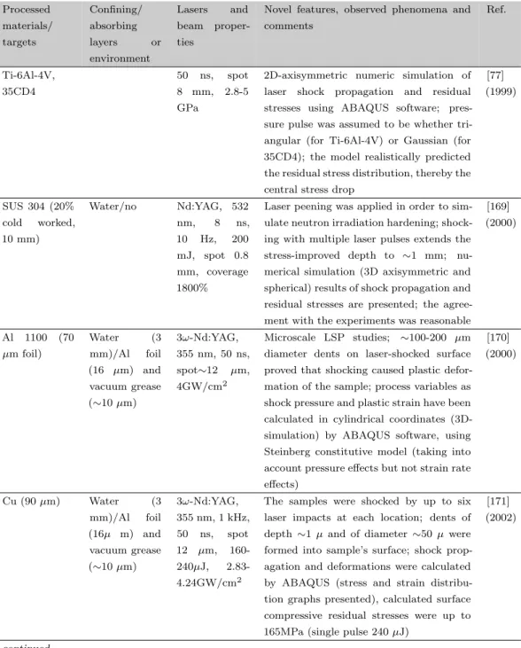
Table C3. Laser Shock Peening literature overview - FEM analyses
Processed materials/ targets Confining/ absorbing layers or environment Lasers and beam proper-tiesNovel features, observed phenomena and comments Ref. Ti-6Al-4V, 35CD4 50 ns, spot 8 mm, 2.8-5 GPa
2D-axisymmetric numeric simulation of laser shock propagation and residual stresses using ABAQUS software; pres-sure pulse was assumed to be whether tri-angular (for Ti-6Al-4V) or Gaussian (for 35CD4); the model realistically predicted the residual stress distribution, thereby the central stress drop
[77] (1999) SUS 304 (20% cold worked, 10 mm) Water/no Nd:YAG, 532 nm, 8 ns, 10 Hz, 200 mJ, spot 0.8 mm, coverage 1800%
Laser peening was applied in order to sim-ulate neutron irradiation hardening; shock-ing with multiple laser pulses extends the stress-improved depth to ∼1 mm; nu-merical simulation (3D axisymmetric and spherical) results of shock propagation and residual stresses are presented; the agree-ment with the experiagree-ments was reasonable
[169] (2000) Al 1100 (70 µm foil) Water (3 mm)/Al foil (16 µm) and vacuum grease (∼10 µm) 3ω-Nd:YAG, 355 nm, 50 ns, spot∼12 µm, 4GW/cm2 Microscale LSP studies; ∼100-200 µm diameter dents on laser-shocked surface proved that shocking caused plastic defor-mation of the sample; process variables as shock pressure and plastic strain have been calculated in cylindrical coordinates (3D-simulation) by ABAQUS software, using Steinberg constitutive model (taking into account pressure effects but not strain rate effects) [170] (2000) Cu (90 µm) Water (3 mm)/Al foil (16µ m) and vacuum grease (∼10 µm) 3ω-Nd:YAG, 355 nm, 1 kHz, 50 ns, spot 12 µm, 160-240µJ, 2.83-4.24GW/cm2
The samples were shocked by up to six laser impacts at each location; dents of depth ∼1 µ and of diameter ∼50 µ were formed into sample’s surface; shock prop-agation and deformations were calculated by ABAQUS (stress and strain distribu-tion graphs presented), calculated surface compressive residual stresses were up to 165MPa (single pulse 240 µJ)
[171] (2002)
Processed materials/ targets Confining/ absorbing layers or environment Lasers and beam proper-ties
Novel features, observed phenomena and comments Ref. 12% Cr steel,Al, 7075-T7351 Pressure pulse 2.5, 10, or 25 ns
Axisymmetric 3D-FEM-simulation of laser peening induced residual stresses; Johnson-Cook plasticity law with isotropic hard-ening, taking into account strain rate de-pendence of the stress was applied pres-sure pulse and HEL were taken from ex-periments; shock propagation and residual stresses distributions are presented for sin-gle and multiple laser impacts; simulation describes the central stress drop
[79] (2003) 35 CD4 50 HRC Water/black paint 30 ns, spot 5x5 mm, 8 GW/cm2, 3 GPa
Numerical simulation of the experiment by Ballard (1991) [264], using a 3D-model in ABAQUS, assuming pressure pulse square in time and uniform over laser spot, and the plastic strain following von Mises yielding criterion with dynamic yield strength HEL(1-2ν)/(1-ν); calculated dy-namic stresses and residual stress profiles are presented for different shock pressures, shock duration, and the number of impacts
[80] (2003) Cu (1 and 3 µm) on Si (111) Water cur-tain/Al foil (16 µm) + vacuum grease Nd:YAG, 355 nm, 50 ns, spot ∼10 µm, ∼209 and 244 µJ, 3.67 and 4.31 GW/cm2
Laser shocking induced stress in Cu layer has been evaluated from structure cur-vature measurements (∼300MPa for 3 µm Cu); an improved analytical model for plasma pressure is presented, taking into account both axial and radial ef-fects (important for small pot size); the stress/strain analysis was performed by ABAQUS software (stress and strain dis-tributions are presented)
[172] (2004) Ti-6Al-4V, Al2024 Nd:YAG, 10 ns, spot 0.75 mm, 0.31 J, 900 impacts/cm2
A 3D-LSP simulation computer program, SHOCKLAS, was developed; examples of simulation the residual stress distribution of given materials at given regime are pre-sented [173] (2005) 35CD4 50 HRC Water/black paint 30 ns, spot 5x5 mm, 8 GW/cm2
3D-FEM analysis of single and multiple LSP by LS-DYNA and ANSYS commer-cial software is described; the target ma-terial was assumed to be perfectly
elastic-[81] (2006)
Processed materials/ targets Confining/ absorbing layers or environment Lasers and beam proper-ties
Novel features, observed phenomena and comments Ref. 35CD4 30 HRC (15 mm) Water 50 ns (Gaus-sian), spot 8 mm, 2.8 GPa
Laser shock propagation in the specimen and residual stresses were calculated by ABAQUS using a 2D axisymmetric model; calculated residual stress distributions are compared with available analytical and experimental results; the size of residual stress field and the depth of the plastic de-formation increases clearly when the diam-eter of the spot is increased from 2 to 8 mm [83] (2006) 12Cr steel, 316L (4 mm) Water/Al (70-80 µm, optional) Pressure dura-tion 6-50 ns, peak pressure 3-5 GPa, im-pact size 1.6 and 5 mm
FEM calculation (2D axisymmetric, by ABAQUS) of shock propagation and resid-ual stresses; materials were given by hy-drodynamic Grueneisen EOS and Johnson-Cook’s plasticity model; effects of impact pressure and diameter, pressure pulse du-ration, number of impacts and of sacrificial overlay were studied numerically; without sacrificial layer, the heating of workpiece by plasma was found to last several mi-croseconds and thermally affected depth was ∼30 µm (6 ns pressure pulse)
[90] (2007)
7050-T7351 Geometrical effects of metallic specimens with curved surface on the residual stress fields produced by LSP process using D FEM analysis and aluminium alloy rods with a middle scalloped section subject to two-sided laser shock peening. Specimens were numerically studied to determine dy-namic and residual stress fields with vary-ing laser parameters and geometrical pa-rameters, e.g. laser power intensity and ra-dius of the middle scalloped section. The geometrical effects of the curved target sur-face greatly influenced residual stress fields
[82] (2008)
Processed materials/ targets Confining/ absorbing layers or environment Lasers and beam proper-ties
Novel features, observed phenomena and comments Ref. 35CD4, 50 HRC steel Water/ black paint 8 GW/cm2, 30 ns, 5 x 5 mm spot
With the FEM model, effects of different overlapping rates and impact sequences on the distribution of residual stresses are sim-ulated. Overlapping laser shock can in-crease the compressive residual stresses, overlapping rate should be optimized for the large area treatment, appropriate over-lapping rate is beneficial to obtain a ho-mogeneous residual stress field, the impact sequence has a great effect on the residual stress field [98] (2008) AISI 52100 steel 4 GW/cm2, 40 ns, 7 mm spot
The effects of parallel multiple laser/material interactions on the stress/strain distributions during LSP. Smaller laser spot decreases the largest magnitude of residual stress and the depth affected by LSP. Larger spots cause more plastic deformation. Spacing between peening zones is critical for the uniformity of mechanical properties across the surface. The greatest uniformity and largest stress magnitudes are achieved by overlapping of the laser spots
[78] (2008) AISI 1045 steel Q-switched Nd:YAG, 10 Hz, 10 ns, 532 nm, output pulse energy 1.03 J, spot radius 1 mm
Simulation of the process of overlapping LSP, including a confined plasma develop-ment model and a finite eledevelop-ment model. The mechanically induced residual stresses were predicted using a newly developed symmetry cell
[174] (2008)
Ti-6Al-4V 5.5-8.3 GPa, 2.8 mm spot
Investigation of the appropriate material model that could be used in LSP simula-tion and design; the effect of multiple non-linear material models for representing the elasticplastic behavior of materials. Elas-tic perfectly plasElas-tic, JohnsonCook and Zer-illiArmstrong models are compared with available experimental results
[91] (2009)
Processed materials/ targets Confining/ absorbing layers or environment Lasers and beam proper-ties
Novel features, observed phenomena and comments Ref. 2024-T351 (2mm) 1-4 GW/cm2, 18 ns, 6-8 mm spot
LSP of thin sheets with reflection of shock waves from the back side of the treated specimen. Different set-ups of laser shock peening process are evaluated and an op-timal set of parameters is suggested for a possible real structure application
[175] (2009)