37
4
4
N
N
e
e
w
w
B
B
l
l
u
u
e
e
t
t
o
o
o
o
t
t
h
h
M
M
o
o
d
d
u
u
l
l
a
a
t
t
o
o
r
r
The introduction of the new Bluetooth standard on chip requires the implementation of the π/4-DQPSK and 8-DPSK modulations. When new features are introduced in a chip, it is appropriate to perform the essential changes only, because this reduces the impact on the already working blocks. In this way, the new implementation is forced to respect some constraints defined by the old chip; moreover, it has to find the best solution in order to minimize chip area and power consumption. Now follows a description of a possible hardware architecture, which follows the Enhanced Data Rate specifications and it will then be added on the BT-GFSK chip. Firstly, it is necessary to introduce some concepts about digital signal filtering and then some filter structures will be investigated, in order to deduce a suitable architecture for approaching our scope. Further, the modulator architecture will be completely examined.
4.1 Digital
Filtering
As shown in the previous chapter, for both of the new EDR modulation schemes it is necessary to implement a square root raised cosine shaping filter (SRRC). This is because before transmitting, the data sequence related to the eight constellation points is filtered through a SRRC digital transmission filter. As known, this impulse time response has an infinite extension and necessitates a truncation to obtain a real implementation. Since this filter impulse response is quite narrow, consideration could be given to a truncated filter shaping into an interval of
[
−NT ,NT]
,where NT value could be between 2T and 3T. Clearly, the truncation involves approximation errors. During simulations investigation isChapter 4 New Bluetooth Modulator
38 made into different values of filter’s length (2·NT), in order to find the best solution to minimize both errors and filter complexity.
Now follow some basic relations to understand how the digital filter works. In the continuous-time case, the filtering is obtained through a convolution, which follows the next equations:
( ) ( )
t = xt ⊗g( )
t =∫
−t∞x( ) (
g t−)
d =∫
−t∞x(
t−) ( )
g dy τ τ τ τ τ τ (4.1)
( )
f X( ) ( )
f G fY = ⋅ (4.2) At this point, the characterisation of discrete-time signals is obtained thanks to an uniformly sampling performed on this continuous-time signal, with a sampling period equal to TC. In this way, the relation of the digital convolution is obtained
(equation 4.4).
y(t) → y[k] , where each signal is given by: s[k]=s(t)t=kTC , (4.3)
[ ] [ ] [ ]
∑
[ ] [
]
∑
[
] [ ]
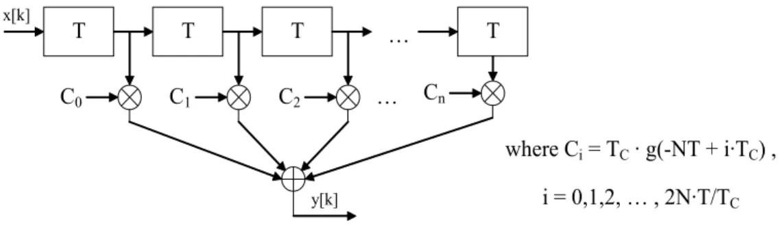
−∞ = −∞ = − = − = ⊗ = k n k n n g n k x T n k g n x T k g k x k y C C (4.4)This is the equation of fundamental importance upon which every digital filter is based on. For a first approach, the relations above could be implemented by a typical FIR filter with the following architecture:
T C0 x[k] T C1 T C2 T Cn … … y[k] where Ci = TC · g(-NT + i·TC) , i = 0,1,2, … , 2N·T/TC
Figure 4.1 – FIR filter internal architecture.
This architecture is composed of an amount of multiplier equal in number to the filter taps, fixed by 2N·T/TC. In this case, the input data are sent every T period
Chapter 4 New Bluetooth Modulator
39 equal to 1 µsec, while the SRRC filter time response is sampled at the highest frequency available on chip, that is exactly 13 MHz; thus the relation
13
1 T
f T
C
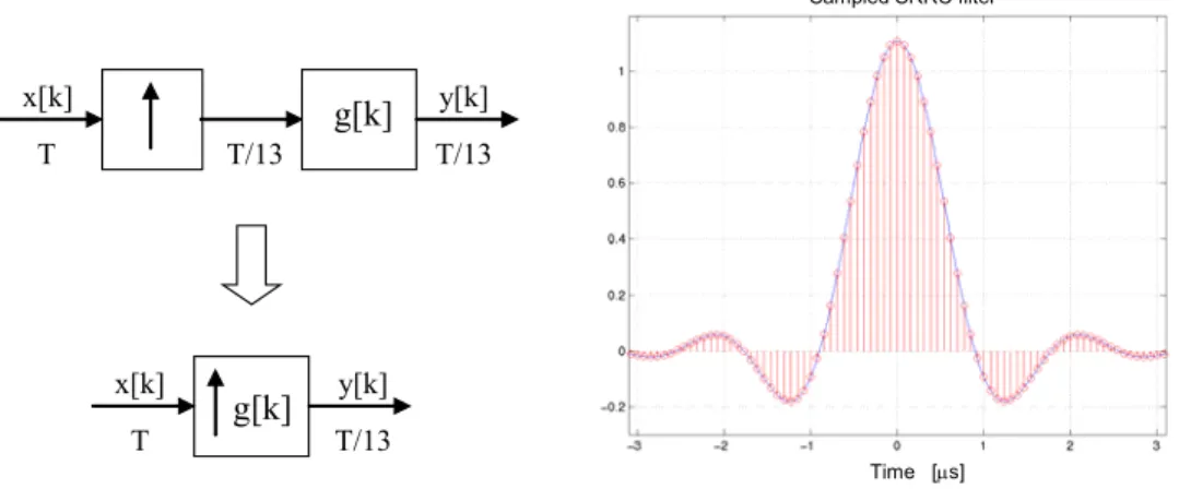
C= = is valid. This is the behaviour of an Interpolator Filter, which
scheme is shown on the left side of Figure 4.2. In this way, the previous relation of the digital convolution is substantially simplified.
x[k] y[k] g[k] x[k] y[k] g[k] T T/13 T/13 T T/13 Time [µs] Sampled SRRC filter
Figure 4.2 – Interpolator Filter scheme and SRRC filter time response sampled @13MHz.
The input data are no longer sampled with a frequency equal to fC, where only 1
data every 13 could be significant (diverse by 0). Thus the next relations are obtained, where many coefficients are equal to 0 and hence they have been removed:
[ ] [ ] [ ]
[ ] [ ] [ ] [ ] [ ] [ ] [ ]
[ ] [ ] [ ] [ ] [ ] [ ] [ ] [ ] [ ]
2 0 50 1 51 2 52 0 50 51 0 52 1 51 0 1 52 0 0 − = − + − + − = − = − + − = − = g x g x g x g x y g x g x g x y g x y = 0 = 0 = 0…
Now it is useful to change the current coefficient notation into the next one, in order to obtain a more clear understanding.
= ⋅ = = ≠ otherwise 0 ] [ 2 2 1 0 where , for 0 x[k] k x T T N , ..., , , i T T i k C C (4.5)
Chapter 4 New Bluetooth Modulator
40 Therefore the relation can be considered:
⋅ = − + ⋅ = = =⋅ 2 ..., 2, 1, 0, where ] [ / C C T T i k T T N n T T n NT g k x X n
g
C i (4.6)In this way, a FIR structure is not suitable, even for the power consumption because every part of this architecture works at the frequency FC = 1/TC.
4.2 Filtering through Look-Up Table
In the previous chapter, the implementation of the GFSK modulator was shown and in that case a ROM for the Gaussian filtering was employed. In fact, that is an implementation through Look-Up Table (LUT). This kind of architecture follows a different approach to digital signal filtering and it is specially used when the input data values belong to a limited amount. Hence it could be suitable in this case, where the input data are one of the eight complex symbols, belonging to the EDR constellation points. A look-up table architecture is composed by a digital buffer that registers the input data sequence, with a length depending on the filter’s length; and a ROM. The data sequence contained into the buffer selects the correct row inside the ROM, where the output data are stored. They are codified on a number of output bits and thanks to the frequency clock, the digital output signal is brought out every TC , where fCK = 1/TC .
ROM
Output bits D/A x[k] B uffe r fCK ŷ(t) Input bits y[k]Chapter 4 New Bluetooth Modulator
41 The most important parameter of this scheme is the ROM size. It is correlated to both filter’s length and sampling frequency, in addition to the number of used bits to codify the input and output data, as specified by the following equation:
bits output # bits input # 2 ⋅ ⋅ C T T (4.7) In this case, the eight constellation points are codified on 3 bits (shown in the next paragraphs), and three different filter’s lengths are investigated:
[
−2T ,2T]
;[
−2.5T ,2.5T]
and[
−3T 3 , T]
.In the first example, the filter has a length of 4T and this means that it has at least 52 filter taps (13x4). If the last coefficient corresponding to g52 = g(2T) is
considered, the filter could have also 53 taps (g0 → g52). In that way it should
involve 5 significant input data during a single step; otherwise only 4 input data are elaborated. In many applications, when it is given a filter length of 2·NT, the filter time response is sampled into
[
−NT ,NT[
;this means that the last coefficient is missed in order to obtain a more uniform architecture. Moreover, the resulting ROM size could be at least 2L time smaller, where L is the bit’s number, using to codify each input data (i.e. : 23 = 8, in this case).Following this example, the ROM size related to the SRRC filter can be simplified once again, if consideration is given to the decomposition of the EDR phase value Φk into both of sine and cosine projections: IK = cos
( )
Φk ,and QK = sin
( )
Φk . As has been shown in the previous chapter, the EDRspecifications give a complete freedom to choose an arbitrary phase for the symbol reference. In order to obtain a symmetric structure of the constellation point, the initial reference phase is set to π/8. In this way, a rigid rotation of π/8 is applied to the previous constellation points, where the reference phase value was fixed to 0. Thus symmetric values can be obtained for IK and QK:
(
)
(
)
(
)
(
)
Chapter 4 New Bluetooth Modulator
42 Now there are four different values for both IK and QK data and each is codified
on 2 bits. It is interesting to make now a comparison with the ROM size related to the eight values of Φk and these two new filter ROMs:
2 2 3 2 bits input # 2 2 2 2 = N⋅ > ⋅ N⋅
The ROM size related to the new IK and QK value is 2 2N-1 times smaller.
Finally, the Odd-symmetry
(
f(−x)=−f(x))
of the input data sequence could be used in order to reduce by as much as half again the ROM size. A simple demonstration considering a filter’s length of 4T, is shown as equations:Input sequence: X = X0 ,X1 ,X2 ,X3
[
] [ ]
(4.8) 39 0 13 3 ) ( : signal Output 39 0 26 1 13 2 0 3g X g X g X g X y y X f + + + = = = + ⋅ =Negate input sequence: −X =−X0 ,−X1 ,−X2 ,−X3
[ ]
39 ( ) (4.9) ) ( : signal Output 3 0 2 13 1 26 0 39 X f y g X g X g X g X X f − = − = = − − − − = −Therefore it is sufficient to add to the LUT scheme, a small size block that checks the sign of the input data sequence. If an appropriate codification of the input data is chosen, such as opposite data value corresponding to complementary bit codifies, it is sufficient to check only the MSB of the input data sequence. The next coding could be a useful coding for IK and QK values:
b1 b0 B1 b0
+cos(π/8) 0 0 +sin(π/8) 0 1
-cos(π/8) 1 1 -sin(π/8) 1 0
Chapter 4 New Bluetooth Modulator
43 At this point, the several ROM sizes related to every filter’s length of interest is summarized (see Table 4.2). The byte values are calculated supposing a number of output bits fixed to 8 and using a sampling frequency of 13MHz.
[-2T, 2T [ ( 4 input data ) [-2.5T, 2.5T [ ( 5 input data ) [-3T, 3T [ ( 6 input data ) 2·2 4·2 ·13 x 8 2·2 5·2 ·13 x 8 2·2 6·2 ·13 x 8 Digital Convolution (6656 x 8 bits) 6.5 Kbytes (26624x 8 bits) 26 Kbytes (106496x 8 bits) 104 Kbytes 2·2 7 ·13 x 8 2·2 9 ·13 x 8 2·2 11 ·13 x 8 Digital Conv.
with Odd-symmetry (3328 x 8 bits)
3.25 Kbytes
(13312 x 8 bits)
13 Kbytes
(53248x 8 bits)
52Kbytes Table 4.2 − Look-Up Table ROM sizes.
4.3 Filtering through Polyphase decomposition
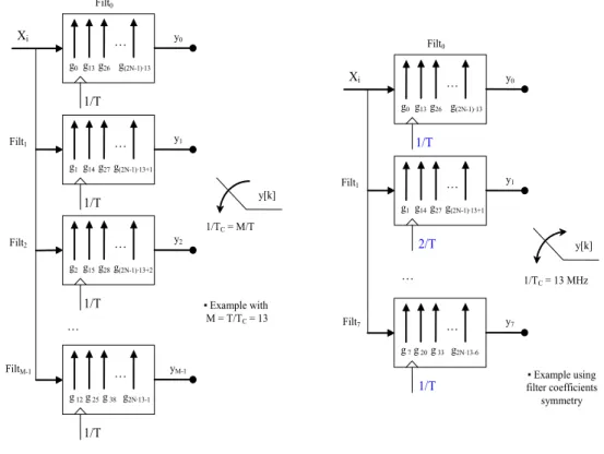
Following a different approach for the implementation of the interpolator filter, a less filled chip area and less power consumption could be obtained. This is possible thanks to a Polyphase Filter Bank (PFB). Filter banks are often used in signal processing applications in order to split the signal into frequency bands and to permit an alias-free reconstruction of the filtered signal, from the individual bands. In this case, it is interesting to analyse the polyphase filter’s working in the time domain. The filter time response, sampled with a frequency FC = 1/TC, can
be divided in M sub-filters, where M = T/TC. During the division, each sub-filter
response is composed by the original time response, shifted every time of 1/TC
and sub-sampled by a factor of M. Inputs signals are sent to every sub-filter and a switching block is able to chose sequentially the output values from the correct sub-filter. In this way, M blocks may be obtain which work with a frequency M time smaller, as shown in the left side of Figure 4.4. Only the switching block
Chapter 4 New Bluetooth Modulator
44 works at the highest frequency 1/TC and thus the total power consumption could
be less than LUT case. Every sub-filter could be implemented in a ROM structure and the total chip area shall be quite similar to the previous look-up table filter implementation. … 1/T 1/TC = M/T Xi y0 … y[k] Filt0 Filt1 Filt2 FiltM-1 g0 g13 g26 g(2N-1)·13 … 1/T y1 g1 g14 g27 g(2N-1)·13+1 … 1/T y2 g2 g15 g28 g(2N-1)·13+2 … 1/T yM-1 g 12 g 25 g 38 g2N·13-1 ▪ Example with M = T/TC = 13 … 1/T Xi y0 y[k] Filt1 g0 g13 g26 g(2N-1)·13 … y1 g1 g14 g27 g(2N-1)·13+1 Filt0 … Filt7 2/T … y7 g 7 g 20 g 33 g2N·13-6 1/TC = 13 MHz
1/T filter coefficients ▪ Example using symmetry
Figure 4.4 – Polyphase Filter network: decomposition and using filter coefficient symmetry.
Moreover, the symmetry between the SRRC filter coefficients can be exploited in order to reduce the area of the sub-filter LUT by almost half. This is obtained thanks to the following relations, using the previous sampling frequency equal to 1/TC = 13 MHz and a M factor of T/TC = 13:
)
(
)
(
t
g
t
g
−
=
→
g
n
=
g
2N⋅13−n
(4.10)Thus, an example may be given with an input sequence: X = X0 ,X1 ,X2 ,X3; and
Chapter 4 New Bluetooth Modulator 45
[
] [ ]
43 3 30 2 17 1 4 0 4 0 17 1 30 2 43 3 48 0 35 1 22 2 9 3 (4.11) 48 9 13 3 ) ( g X g X g X g X g X g X g X g X g X g X g X g X y y X f + + + = = + + + = ↓ ↓ ↓ ↓ = + + + = = + ⋅ =Now consideration is given to the output value depending on the reverse input sequence: Z = X3 ,X2 ,X1 ,X0; and the following is obtained:
[
]
[ ]
[ ]
48 ( ) (4.12) 43 ' 4 13 3 ' ) ( 0 4 1 17 2 30 3 43 X f y g X g X g X g X y y Z f = = = + + + = = + ⋅ =Finally, the relation of interest is given by:
[
]
[
13 13]
(4.13) 13 , , , ) 13 3 ( ) 13 2 ( ) 13 ( d , , , Xa Xb Xc Xd n a n b n c n Xd Xc Xb Xa n k y g X g X g X g X n k y − + ⋅ = = + + + = + ⋅ + ⋅ + ⋅ +In this way, every T period the correct sequence of sub-filter output values is: Filt0, Filt1, Filt2, Filt3, Filt4, Filt5, Filt6, Filt7; and Filt6, Filt5, Filt4, Filt3, Filt2, Filt1,
afterwards the input sequence has been reversed. Therefore, using a truncated filter response into
[
−NT ,NT[
;Filt0 and FiltM/2+1 are polled only once a Tperiod, while the other sub-filters work with a frequency twice as big.
For example, using an M = 13 and a T period equal to 1 µsec, (M/2 + 1) = 7 sub-filters are obtained: two working at 1 MHz and five working at 2 MHz. With regard to the ROM size, the sub-filters chip area is 13/7 times smaller than both the complete polyphase network and the previous LUT implementation. Also, it may be useful to explain the working using a sampling frequency of 26MHz, as it will be analysed in the next chapter. In this case an M factor equal to 26 is obtained; and 14 sub-filters result.
Furthermore, the Odd-symmetry of the input sequence could be still used and now the resulting ROM sizes of the polyphase decomposition are given. The byte values are calculated supposing a number of output bits fixed to 8 and using a sampling frequency of 13MHz.
Chapter 4 New Bluetooth Modulator 46 [-2T, 2T [ ( 4 input data ) [-2.5T, 2.5T [ ( 5 input data ) [-3T, 3T [ ( 6 input data ) 2·2 4·2 ·7 x 8 2·2 5·2 ·7 x 8 2·2 6·2 ·7 x 8 Polyphase Filter
with filter coeff.
Symmetry (3584x 8 bits) 3.5 Kbytes (14336x 8 bits) 14 Kbytes (57344x 8 bits) 56 Kbytes 2·2 7 ·7 x 8 2·2 9 ·7 x 8 2·2 11 ·7 x 8 Polyphase Filter
with coeff. Symm &
Odd-symmetry (1792x 8 bits) 1.75 Kbytes (7168 x 8 bits) 7 Kbytes (28672x 8 bits) 28Kbytes Table 4.3 − Polyphase Filter ROM sizes.
An implementation that involves a smaller chip area might be obtained. If a higher frequency clock is available, the operations made by two separate ROM filters (such as IK and QK filtering) could be executed by a single block that works using
a clock with a frequency twice as high. In this case, using a filter based on Look-up table implementation, a frequency clock as much as 26MHz shall be necessary, but it is outside the limit of 13MHz. Instead, however, it is possible with Polyphase decomposition: every single sub-filter shall work with a frequency twice as high. Thus this frequency clock should be shifted from 1MHz to 2MHz; or from 2MHz into 4 MHz. In the present GFSK chip a frequency of 4MHz is not available; therefore this last case has not been implemented.
4.4 Architecture of the new BT- Modulator
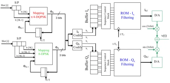
Finally, a description follows of the most important blocks that make up the new Bluetooth modulator. As shown in the next figure, the binary data are first converted to 2-bits or 3-bits parallel data, depending on which kind of modulation is used (π/4-DQPSK or 8-DPSK, respectively).
Chapter 4 New Bluetooth Modulator 47 Mapping π/4-DQPSK ΦK-1 Slot [i] ΦK S/P b [2K-1] b [2K] Slot [i] S/P Mapping 8-DPSK ΦK-1 ΦK b [3K] b [3K-1] b [3K-2] B uffe r IK 3 bits 3 bits 1/T 1/T ROM - IK Filtering Se que nc e C ont rol blo ck 1/TC IKf Bu ffe r Q K ROM - QK Filtering Se que nc e C ont rol blo ck 1/TC QKf IK Codify b0 b1 b0 b1 cos (2πfot) sin (2πfot) v(t) D/A D/A QK Codify
Figure 4.5 – Scheme of the Bluetooth EDR modulator.
Thanks to the Mapping blocks, the data are differentially encoded to one of the eight possible phase values, codified on 3 bits. Both of these blocks follow the EDR specifications, mentioned in the previous chapter and here only a summary of their sequential working is given, as explained in tables 4.4-b and 4.5.
IK
ΦK QK
Codify PhaseNext 00 01 11 10
00 Φ0 π/8 01 Φ0 Φ1 Φ3 Φ5 Φ7 01 Φ1 3π/8 00 Φ1 Φ2 Φ4 Φ6 Φ0 10 Φ2 5π/8 00 Φ2 Φ3 Φ5 Φ7 Φ1 11 Φ3 7π/8 01 Φ3 Φ4 Φ6 Φ0 Φ2 11 Φ4 -7π/8 10 Φ4 Φ5 Φ7 Φ1 Φ3 10 Φ5 -5π/8 11 Φ5 Φ6 Φ0 Φ2 Φ4 01 Φ6 -3π/8 11 Φ6 Φ7 Φ1 Φ3 Φ5 00 Φ7 -π/8 10 Current Phase Φ7 Φ0 Φ2 Φ4 Φ6
Table 4.4 − a) IK and QK codify of the ΦK angles; b) π/4-DQPSK mapping.
Chapter 4 New Bluetooth Modulator
48 The output phase ΦK is codified in In-phase and In-quadrature components in
order to obtain the two separate values (see table 4.4-a). Both of 2-bits IK and QK
values are stored into two different Buffers. Each is a shift-register and its length depends on the length of the filter being used. It could be: 4 x 2-bits in case of
[
−2T ,2T[
;instead 5 x 2-bits for[
−2.5T ,2.5T[
or 6 x 2-bits for[
−3T ,3T[
. These buffers store the input data sequences for the SRRC filtering. As has been described, a Sequence Control block could be necessary to check the Odd-symmetry of the sequence or to calculate the reverse data sequence, if a polyphase filtering with symmetric coefficients is used. Finally, the Interpolator filter is implemented through look-up table or polyphase filter network, as previously clarified. Next Phase 000 001 011 010 110 111 101 100 Φ0 Φ0 Φ1 Φ2 Φ3 Φ4 Φ5 Φ6 Φ7 Φ1 Φ1 Φ2 Φ3 Φ4 Φ5 Φ6 Φ7 Φ0 Φ2 Φ2 Φ3 Φ4 Φ5 Φ6 Φ7 Φ0 Φ1 Φ3 Φ3 Φ4 Φ5 Φ6 Φ7 Φ0 Φ1 Φ2 Φ4 Φ4 Φ5 Φ6 Φ7 Φ0 Φ1 Φ2 Φ3 Φ5 Φ5 Φ6 Φ7 Φ0 Φ1 Φ2 Φ3 Φ4 Φ6 Φ6 Φ7 Φ0 Φ1 Φ2 Φ3 Φ4 Φ5 Current Phase Φ7 Φ7 Φ0 Φ1 Φ2 Φ3 Φ4 Φ5 Φ6 Table 4.5 − 8-DPSK mapping.4.5 Power Spectral Density of the modulated signal
Following discussion of the cost of the implementation of the new modulator in terms of total size occupied by ROM table, further consideration is now given to power emitted by the transmitter in order to reduce the interferences with adjacent
Chapter 4 New Bluetooth Modulator
49 channels. The Enhanced Data Rate specifications regulate the In-band and Out-band emissions. Firstly, consideration is give to the signal power related to the band between 1MHz and 1.5 MHz far from the frequency carrier. The limit to check is an attenuation of the power at least 26 dB from the maximum In-band value. With regards to the power of adjacent ISM channels, (which are at least 2 MHz away from the frequency carrier) there are other limits: for the second adjacent channel, the power measurements over a 1 MHz band have not to exceed -20 dBm, while for the third and subsequent adjacent channels the value to be respected is -40 dBm.
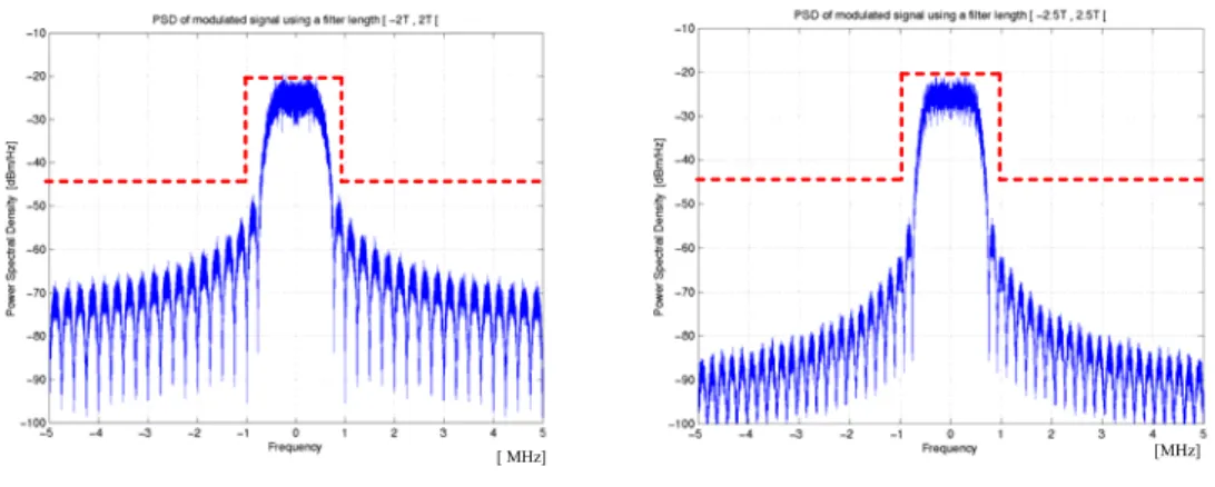
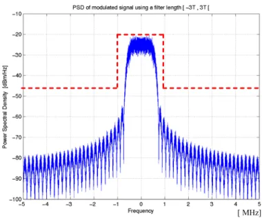
It is however difficult to make an exact evaluation of the Power Spectral Density (PSD) of the modulated signal, in the absence of an exact model for the analog filter. To this aim, only the PSD of the modulated baseband signals can be plotted, employing a filter length of
[
−2T ,2T[
;[
−2.5T ,2.5T[
and[
−3T ,3T[
. The principal limits are outlined by a red-shape on the following figures.Comparing the three figures, a filter length of 4T strictly respects the attenuation value; while using both the other filter length the limit is respected with a margin about 40 dB. As hinted above, these are only the PSD of the modulated signal, before transmission block. This means that thanks to the analog transmission filter, the performances could be improved, taking care to the correct design of the transmitter circuit.
[ MHz] [MHz]
Chapter 4 New Bluetooth Modulator
50
[ MHz]