3. Standard
IEEE
802.16
Commonly referred to as WiMAX or less commonly as WirelessMAN™ or the Air Interface
Standard, IEEE 802.16 is a specification for fixed broadband wireless metropolitan access networks
(MANs). Published on April 8, 2002, the standard defines the use of bandwidth between the licensed 10GHz and 66GHz and between the 2GHz and 11GHz frequency ranges and defines a MAC layer that supports multiple physical layer specifications customized for the frequency band of use and their associated regulations. 802.16 supports very high bit rates in both uploading to and downloading from a base station up to a distance of 30 miles to handle such services as VoIP, IP connectivity and TDM voice and data.
Figure 3.1 – How wimax works.
As currently defined through IEEE Standard 802.16, a wireless MAN provides network access to buildings through exterior antennas communicating with central radio base stations (BSs).
The stations with which a station has direct links are called neighbors and shall form a neighborhood. A node’s neighbors are considered to be “one hop” away from the node. A two-hop extended neighborhood contains, additionally, all the neighbors of the neighborhood.
The wireless MAN offers an alternative to cabled access networks, such as fiber optic links, coaxial systems using cable modems, and digital subscriber line (DSL) links. Because wireless systems have the capacity to address broad geographic areas without the costly infrastructure development required in deploying cable links to individual sites, the technology may prove less expensive to deploy and may lead to more ubiquitous broadband access. WirelessMAN technology bringing the network to a building, users inside the building will connect to it with conventional in-building
802.11). However, the fundamental design of the standard may eventually allow for the efficient
extension of the WirelessMAN networking protocols directly to the individual user.
The standard is intended to allow for multiple vendors to produce interoperable equipment. However, it also allows for extensive vendor differentiation.
Development of IEEE Standard 802.16 and the included WirelessMAN™ air interface, along with associated standards and amendments, is the responsibility of IEEE Working Group 802.16 on
Broadband Wireless Access (BWA) Standards [31].
Historically, the 802.16 activities were initiated at an August 1998 meeting called by the National Wireless Electronics Systems Testbed (N-WEST) of the U.S. National Institute of Standards and Technology.
3.1 MAC
(Medium Access Control)
The IEEE 802.16 MAC protocol was designed for point-to-multipoint broadband wireless access applications. It addresses the need for very high bit rates, both uplink (to the BS) and downlink (from the BS). Access and bandwidth allocation algorithms must accommodate hundreds of terminals per channel, with terminals that may be shared by multiple end users. The request-grant mechanism is designed to be scalable, efficient, and self-correcting.
The MAC includes Service-Specific Convergence Sublayers (CS) that interface to higher layers, above the core MAC common part sublayer that carries out the key MAC functions.
The Service-Specific Convergence Sublayer provides any transformation or mapping of external network data, received through the CS Service Access Point (SAP), into MAC SDUs received by the
MAC Common Part Sublayer (CPS) through the MAC SAP. This includes classifying external
network Service Data Units (SDUs) and associating them to the proper MAC Service Flow
Identifier (SFID) and Connection Identifier (CID). It may also include such functions as Payload Header Suppression (PHS). Multiple CS specifications are provided for interfacing with various
protocols. The internal format of the CS payload is unique to the CS, and the MAC CPS is not required to understand the format of or parse any information from the CS payload.
The MAC CPS provides the core MAC functionality of system access, bandwidth allocation, connection establishment, and connection maintenance. It receives data from the various CSs, through the MAC SAP, classified to particular MAC connections.
Figure 3.2 – IEEE Std 802.16 protocol layering.
IEEE Standard 802.16 defines two general service-specific convergence sublayers for mapping services to and from 802.16 MAC connections:
• ATM convergence sublayer: it is defined for ATM services.
• Packet convergence sublayer: it is defined for mapping packet services such as IPv4, IPv6, Ethernet, and virtual local area network (VLAN).
The primary task of the sublayer is to classify service data units to the proper MAC connection, preserve or enable QoS, and enable bandwidth allocation. The MAC also contains a separate security sublayer providing authentication, secure key exchange, and encryption.
CS provides a mechanism for requesting bandwidth, associating QoS and traffic parameters, transporting and routing data to the appropriate convergence sublayer, and all other actions associated with the contractual terms of the service.
Connections are referenced with 16-bit connection identifiers and may require continuously granted bandwidth or bandwidth on demand.
Each SS has a standard 48-bit MAC address, but this serves mainly as an equipment identifier, since the primary addresses used during operation are the CIDs. Upon entering the network, the SS is assigned three management connections in each direction. These three connections reflect the three different QoS requirements used by different management levels.
The PHY definition includes multiple specifications, each appropriate to a particular frequency range and application.
3.1.1 Service-specific CS
The service-specific CS resides on top of the MAC CPS and utilizes, via the MAC SAP, the services provided by the MAC CPS.
The CS performs the following functions utilizing the services of the MAC: • Accepting higher-layer Protocol Data Units (PDUs).
• Performing classification of PDUs into the appropriate connection. • Processing (if required) the PDUs based on the classification. • Suppression of payload header information (optional).
• Delivering CS PDUs to the appropriate MAC SAP associated with the service flow for transport to the peer MAC SAP.
• Receiving CS PDUs from the peer entity.
• Rebuilding of any suppressed payload header information (optional).
The sending CS is responsible for delivering the MAC SDU to the MAC SAP. The MAC is responsible for delivery of the MAC SDU to peer MAC SAP in accordance with the QoS, fragmentation, concatenation, and other transport functions associated with a particular connection’s service flow characteristics. The receiving CS is responsible for accepting the MAC SDU from the peer MAC SAP and delivering it to a higher-layer entity.
The packet CS is used for transport for all packet-based protocols such as Internet Protocol (IP),
Point-to-Point Protocol (PPP), and IEEE Std 802.3 (Ethernet).
3.1.2 MAC SDU Formats
Once classified and associated with a specific MAC connection, higher-layer PDUs shall be encapsulated in the MAC SDU format as illustrated in Figure3.3. The 8-bit Payload Header
Suppression Index (PHSI) field shall be present when a Payload Header Suppression (PHS) rule
Figure 3.3 – MAC SDU format.
MAC SDU is mapped onto a particular connection for transmission between MAC peers. The mapping process associates a MAC SDU with a connection, which also creates an association with the service flow characteristics of that connection. This process facilitates the delivery of MAC SDUs with the appropriate QoS constraints.
3.1.3 MAC Header
Two MAC header formats are defined distinguishes by single-bit Header Type (HT) field.
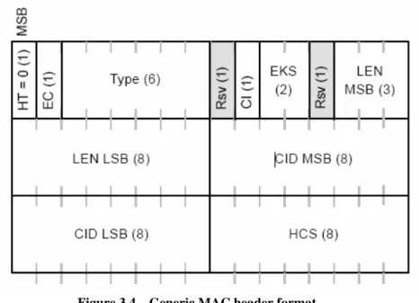
Generic MAC header
This header begins each MAC PDU containing either MAC management messages or CS data. The fields of the generic MAC header are defined in Table 3.1.
Table 3.1 – Generic MAC header fields.
Bandwidth request header
It is used to request additional bandwidth. The bandwidth request header is illustrated in Figure 3.5.
Figure 3.5 – Bandwidth request header format.
The Bandwidth Request shall have the following properties: • The length of the header shall always be 6 bytes.
• The EC field shall be set to 0, indicating no encryption.
• The CID shall indicate the connection for which uplink bandwidth is requested.
• The Bandwidth Request (BR) field shall indicate the number of bytes requested. The allowed types for bandwidth requests are “000” for incremental and “001” for aggregate.
The HT field shall be set to zero for the Generic Header and to one for a bandwidth request header.
3.1.4 MAC PDU Formats
The MAC PDU is the data unit exchanged between the MAC layers of the BS and its SSs. A MAC PDU consists of:
• A fixed-length MAC header.
• A variable-length payload. If present, the payload shall consist of zero or more subheaders and zero or more MAC SDUs and/or fragments thereof. The payload information may vary in length, so that a MAC PDU may represent a variable number of bytes. This allows the MAC to tunnel various higher-layer traffic types without knowledge of the formats or bit patterns of those messages.
• An optional Cyclic Redundancy Check (CRC).
Figure 3.6 – MAC PDU formats.
Except for bandwidth request MAC PDUs, which contain no payload, MAC PDUs contain either MAC management messages or convergence sublayer data.
Fields specified as SDUs or SDU fragments (for example, MAC PDU payloads) are transmitted in the same order of bytes as received from upper layers.
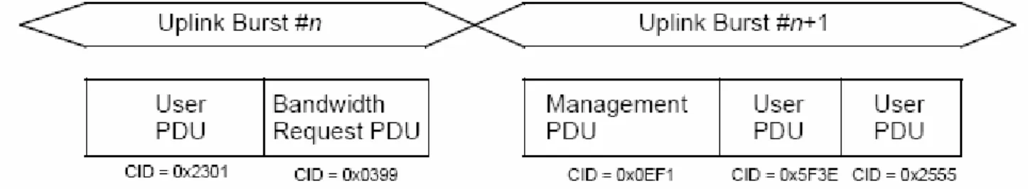
Multiple MAC PDUs may be concatenated into a single transmission in either the uplink or downlink directions. Figure 3.7 illustrates this concept for an uplink burst transmission.
Since each MAC PDU is identified by a unique CID, the receiving MAC entity is able to present the MAC SDU (after reassembling the MAC SDU from one or more received MAC PDUs) to the correct instance of the MAC SAP. MAC Management messages, user data, and bandwidth request MAC PDUs may be concatenated into the same transmission.
Fragmentation
Fragmentation is the process by which a MAC SDU is divided into one or more MAC PDUs. This process is undertaken to allow efficient use of available bandwidth relative to the QoS requirements of a connection’s service flow. Capabilities of fragmentation and reassembly are mandatory.
The authority to fragment traffic on a connection is defined when the connection is created by the MAC SAP. Fragmentation may be initiated by a BS for downlink connections and by an SS for uplink connections.
Non-ARQ Connections
For non-ARQ connections, fragments are transmitted once and in sequence. The sequence number assigned to each fragment allows the receiver to recreate the original payload and to detect the loss of any intermediate packets. A connection may be in only one fragmentation state at any given time. Upon loss, the receiver shall discard all MAC PDUs on the connection until a new first fragment is detected or a non-fragmented MAC PDU is detected.
ARQ Connections
For ARQ-enabled connections, fragments are formed for each transmission by concatenating sets of ARQ blocks with adjacent sequence numbers.
Packing
If packing is turned on for a connection, the MAC may pack multiple MAC SDUs into a single MAC PDU. Packing makes use of the connection attribute indicating whether the connection carries fixed-length or variable-length packets. The transmitting side has full discretion whether or not to pack a group of MAC SDUs in a single MAC PDU. The capability of unpacking is mandatory. The construction of PDUs varies for ARQ and non-ARQ connections with respect to packing and fragmentation syntax.
Cyclic Redundancy Check
A service flow may require that a CRC be added to each MAC PDU carrying data for that service flow. In this case, for each MAC PDU with HT=0, a CRC, shall be appended to the payload of the MAC PDU.
The CRC shall cover the generic MAC header and the Payload of the MAC PDU. The CRC shall be calculated after encryption; i.e., the CRC protects the Generic Header and the ciphered Payload.
Security Association
When transmitting a MAC PDU on a connection that is mapped to a Security Association (SA), the sender shall perform encryption and data authentication of the MAC PDU payload as specified by that SA. When receiving a MAC PDU on a connection mapped to an SA, the receiver shall perform decryption and data authentication of the MAC PDU payload, as specified by that SA.
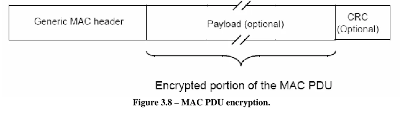
The generic MAC header shall not be encrypted. The Header contains all the encryption information needed to decrypt a Payload at the receiving station.
Figure 3.8 – MAC PDU encryption.
Encryption of the payload is indicated by the EC bit field. A value of 1 indicates the payload is encrypted and the EKS field contains meaningful data. A value of 0 indicates the payload is not encrypted. Any unencrypted MAC PDU received on a connection mapped to an SA requiring encryption shall be discarded.
Padding
Allocated space within a data burst that is unused shall be initialized to a known state. This may be accomplished by setting each unused byte to the stuff byte value (0xFF). If the size of the unused region is at least the size of a MAC header, the region may also be initialized by formatting the unused space as an MAC PDU. When doing so, the MAC header CID field shall be set to the value of the Padding CID, the CI, EC, HT, and Type fields shall be set to zero, the length field shall be set to the number of unused bytes (including the size of the MAC header created for the padding MAC PDU) in the data burst, and the HCS shall be computed in the normal way.
3.2
MAC Common Part Sublayer
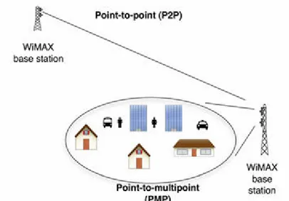
A network that utilizes a shared medium (the space through which the radio waves propagate) shall provide an efficient sharing mechanism. The 802.16 standard specifies two modes for sharing the wireless medium: point-to-multipoint (PMP) and mesh (optional).
3.2.1 PMP (Point-to-MultiPoint)
Figure 3.9 – Point-to point and point-to-multipoint configurations.
One base station can service hundreds of dissimilar subscribers in terms of bandwidth and services offered.
With PMP, the BS serves a set of SSs within the same antenna sector in a broadcast manner, within a given frequency channel and antenna sector, all stations receive the same transmission, or parts thereof. Transmissions from SSs are directed to and centrally coordinated by the BS.
The BS is the only transmitter operating in downlink, so it transmits without having to coordinate with other stations, except for the overall Time Division Duplexing (TDD) that may divide time into uplink and downlink transmission periods.
Figure 3.10 – Time division duplexing.
In the downlink (from BS to SS) subframe, the BS transmits a burst of MAC Protocol Data Units (PDUs). Since the transmission is broadcast, all SSs listen to the data transmitted by the BS. In cases where the DL-MAP does not explicitly indicate that a portion of the downlink subframe is for a specific SS, all SSs capable of listening to that portion of the downlink subframe shall listen. The SSs check the CIDs in the received PDUs and retain only those PDUs addressed to them.
In the uplink (from SS to BS) any SS transmits a burst of MAC PDUs to the BS in a Time-Division
Multiple Access (TDMA) manner. Based on measurements at the physical layer, any SS adapts over
time the Interval Usage Code (IUC) in use, that is, modulation, rate, and Forward Error Correction (FEC) scheme, for both downlink (downlink IUC, DIUC) and uplink (uplink IUC, UIUC) transmissions.
Downlink and uplink subframes are duplexed using one of the following techniques:
• Frequency-Division Duplex (FDD) is where downlink and uplink subframes occur simultaneously on separate frequencies.
Figure 3.11 – FDD.
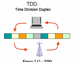
• Time-Division Duplex (TDD) is where downlink and uplink subframes occur at different times and usually share the same frequency.
Figure 3.12 – TDD.
Sometimes FDD and TDD are simultaneously. Both TDD and FDD alternatives support adaptive burst profiles in which modulation and coding options may be dynamically assigned on a burst-by-burst basis.
SSs can be either full duplex (i.e., they can transmit and receive simultaneously) or half-duplex (i.e., they can transmit and receive at nonoverlapping time intervals).
The MAC protocol is connection-oriented: all data communications, for both transport and control, are in the context of a unidirectional connection.
At the start of each frame, the BS schedules the uplink and downlink grants in order to meet the negotiated QoS requirements. Each SS learns the boundaries of its allocation within the current uplink subframe by decoding the UL-MAP message.
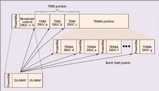
The downlink subframe starts with a frame control section that contains the DL-MAP for the current downlink frame; this message contains the timetable of the downlink grants, as well as the UL-MAP for a specified time in the future.
DL-MAP and UL-MAP are transmitted by the BS at the beginning of each downlink subframe for both FDD and TDD modes.
The downlink map specifies when physical layer transitions (modulation and FEC changes) occur within the downlink subframe. The downlink subframe typically contains a TDM portion immediately following the frame control section.
In FDD systems, the TDM portion may be followed by a TDMA segment that includes an extra preamble at the start of each new burst profile. This feature allows better support of half-duplex SSs. In an efficiently scheduled FDD system with many half-duplex SSs, some may need to transmit earlier in the frame than they receive. Due to their half-duplex nature, these SSs lose synchronization with the downlink; the TDMA preamble allows them to regain synchronization. The SSs transmit in their assigned allocation using the burst profile specified by the Uplink Interval
Usage Code (UIUC) in the UL-MAP entry granting them bandwidth.
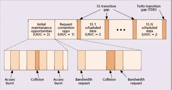
The downlink subframe is shown in Figure 3.13 and the uplink subframe is show in Figure 3.14.
Figure 3.14 – The uplink subframe structure.
For the purposes of mapping to services on SSs and associating varying levels of QoS, all data communications are in the context of a connection. Service flows may be provisioned when an SS is installed in the system. Shortly after SS registration, connections are associated with these service flows (one connection per service flow) to provide a reference against which to request bandwidth. Additionally, new connections may be established when a customer’s service needs change. A connection defines both the mapping between peer convergence processes that utilize the MAC and a service flow. The service flow defines the QoS parameters for the PDUs that are exchanged on the connection.
The concept of a service flow on a connection is central to the operation of the MAC protocol. Service flows provide a mechanism for uplink and downlink QoS management. An SS requests uplink bandwidth on a per connection basis (implicitly identifying the service flow). Bandwidth is granted by the BS to an SS as an aggregate of grants in response to per connection requests from the SS.
Since the BS controls the access to the medium in the uplink direction, bandwidth is granted to SSs on demand. For this purpose, a number of different bandwidth-request mechanisms have been specified:
• Unsolicited granting: a fixed amount of bandwidth on a periodic basis is requested during the setup phase of an uplink connection. After that phase, bandwidth is never explicitly requested. • Unicast poll: consists of allocating to a polled uplink connection the bandwidth needed to
transmit a bandwidth request. If the polled connection has no data awaiting transmission or if it has already requested bandwidth for all of its backlog, it will not reply to the unicast poll, which is thus wasted.
• Broadcast polls: are issued by the BS to all uplink connections. The main drawback in this mechanism is that a collision occurs whenever two or more uplink connections send a bandwidth request by responding to the same poll, in which case a truncated binary exponential backoff algorithm is employed.
• Piggybacked on a PDU: this mechanism is effective only if the connection has some backlog for which bandwidth reservation has already been issued.
The 802.16 MAC specifies four different scheduling services in order to meet the QoS requirements of multimedia applications:
• Real-time polling service (rtPS). • Non-real-time polling service (nrtPS). • Best effort (BE).
Each scheduling service is characterized by a mandatory set of QoS parameters, which is tailored to best describe the guarantees required by the applications.
Each SS shall have a 48-bit universal MAC address; this address uniquely defines the SS from within the set of all possible vendors and equipment types. It is used during the initial ranging process to establish the appropriate connections for an SS. It is also used as part of the authentication process by which the BS and SS each verify the identity of the other.
Connections are identified by a 16-bit CID. The message dialogs provide three CID values. The same CID value is assigned to both members (uplink and downlink) of each connection pair. The use of a 16-bit CID permits a total of 64K connections within each downlink and uplink channel. The CID can be considered a connection identifier even for nominally connectionless traffic like IP, since it serves as a pointer to destination and context information. Requests for transmission are based on these CIDs, since the allowable bandwidth may differ for different connections, even within the same service type. The type of service and other current parameters of a service are implicit in the CID; they may be accessed by a lookup indexed by the CID.
At SS initialization, two pairs of management connections (uplink and downlink) shall be established between the SS and the BS and a third pair of management connections may be optionally generated. The three pairs of connections reflect the fact that there are inherently three different levels of QoS for management traffic between an SS and the BS.
• Basic connection: is used by the BS MAC and SS MAC to exchange short, time-urgent MAC management messages.
• Primary management connection: is used by the BS MAC and SS MAC to exchange longer, more delay-tolerant MAC management messages.
• Secondary management connection: is used by the BS and SS to transfer delay tolerant, standards-based messages:
Dynamic Host Configuration Protocol (DHCP). Trivial File Transfer Protocol (TFTP).
SNMP. Etc.
These messages are carried in IP datagrams and they may be packed and/or fragmented. Air interface specifications are:
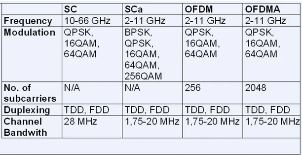
• WirelessMAN-SC2: uses a single-carrier modulation format.
• WirelessMAN-OFDM: uses orthogonal frequency-division multiplexing with a 256-point transform. Access is by TDMA. This air interface is mandatory for license exempt bands.
• WirelessMAN-OFDMA: uses orthogonal frequency-division multiple access with a 2048-point transform. In this system, multiple access is provided by addressing a subset of the multiple carriers to individual receivers.
Figure 3.15 – Air interface specifications.
Use of the secondary management connection is required only for managed SS.
For the SCa, OFDM, and OFDMA PHY layers, management messages shall have CRC.
Connections, once established, may require active maintenance. The maintenance requirements vary depending upon the type of service connected.
Finally, connections may be terminated. This generally occurs only when a customer’s service contract changes. The termination of a connection is stimulated by the BS or SS.
3.2.2 MESH Networks
In mesh mode, traffic can be routed through other SSs and can occur directly among SSs. Access coordination is distributed among the SSs. Depending on the transmission protocol algorithm used, this can be done on the basis of equality using distributed scheduling, or on the basis of superiority of the Mesh BS, which effectively results in centralized scheduling, or on a combination of both.
Distributed scheduling
All the nodes including the Mesh BS shall coordinate their transmissions in their two-hop neighborhood and shall broadcast their schedules (available resources, requests and grants) to all their neighbors. Optionally the schedule may also be established by directed uncoordinated requests and grants between two nodes. Nodes shall ensure that the resulting transmissions do not cause collisions with the data and control traffic scheduled by any other node in the two-hop neighborhood. There is no difference in the mechanism used in determining the schedule for downlink and uplink.
Centralized scheduling
Resources are granted in a more centralized manner. The Mesh BS shall gather resource requests from all the Mesh SSs within a certain hop range. It shall determine the amount of granted resources for each link in the network both in downlink and uplink, and communicates these grants to all the Mesh SSs within the hop range. The grant messages do not contain the actual schedule, but each node shall compute it by using the predetermined algorithm with given parameters.
All the communications are in the context of a link, which is established between two nodes. One link shall be used for all the data transmissions between the two nodes. QoS is provisioned over links on a message-by-message basis. No service or QoS parameters are associated with a link, but each unicast message has service parameters in the header. Traffic classification and flow regulation are performed at the ingress node by upper-layer classification/regulation protocol. The service parameters associated with each message shall be communicated together with the message content via the MAC SAP.
Mesh systems typically use omnidirectional antennas, but can also be co-located using sector antennas. At the edge of the coverage area of the Mesh network, where only a connection to a single point is needed, even highly directional antennas can be used.
Each node shall have a 48-bit universal MAC address, as defined in IEEE Std 802-2001. The address uniquely defines the node from within the set of all possible vendors and equipment types. This address is used during the network entry process and as part of the authorization process by which the candidate node and the network verify the identity of each other.
When authorized to the network the candidate node shall receive a 16-bit node identifier (Node ID) upon a request to the Mesh BS. Node ID is the basis for identifying nodes during normal operation. The Node ID is transferred in the Mesh subheader, which follows the generic MAC header, in both unicast and broadcast messages.
For addressing nodes in the local neighborhood, 8-bit link identifiers (Link IDs) shall be used. Each node shall assign an ID for each link it has established to its neighbors. The Link IDs are communicated during the Link Establishment process as neighboring nodes establish new links. The
Link ID is transmitted as part of the CID in the generic MAC header in unicast messages. The Link IDs shall be used in distributed scheduling to identify resource requests and grants. Since these messages are broadcast, the receiver nodes can determine the schedule using the transmitter’s Node ID in the Mesh subheader, and the Link ID in the payload of the MSH-DSCH (Mesh Mode Schedule
with Distributed Scheduling) message.
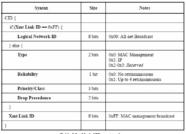
The Connection ID in Mesh mode is specified as shown in Table 3.2 to convey broadcast/unicast, service parameters, and the link identification.
Table 3.2 – Mesh CID construction.
• Priority/Class: priority field indicates message class.
• Drop Precedence: messages with larger Drop Precedence shall have higher dropping likelihood during congestion.
3.3
MAC Management Messages
MAC Management messages shall be carried in the payload of the MAC PDU. All MAC Management messages begin with a Management Message Type field and may contain additional fields. MAC Management messages on the Basic, Broadcast, and Initial Ranging connections shall neither be fragmented nor packed. MAC Management messages on the Primary Management Connection may be packed and/or fragmented.
For the SCa, OFDM, and OFDMA PHY layers, management messages carried on the Initial Ranging, Broadcast, Basic, and Primary Management connections shall have CRC usage enabled. The format of the Management message is given in Figure 3.16.
Figure 3.16 – MAC Management message format.
Table 3.3 – MAC Management messages.
In the following I describe only MSH-NCFG message and MSH-DSCH message because these are important for my work.
3.3.1 MSH-NCFG Message
MSH-NCFG messages provide a basic level of communication between nodes in different nearby networks whether from the same or different equipment vendors or wireless operators. All the nodes (BS and SS) in the Mesh network shall transmit MSH-NCFGs.
Table 3.4 – MSH-NCFG message format.
• NumNbrEntries: number of neighbors reported on in the message. The number of neighbors reported on may be a fraction of the whole set of neighbors known to this node. A node can report on subsequent subsets of neighbors in its subsequent MSH-NCFG transmissions.
• N270umBSEntries: number of Mesh BS neighbors reported on in this message. • XmtAntenna: the logical antenna used for transmission of this message.
• Network base channel: the base channel being used in this node’s network, which is the logical number of the physical channel, shall be used to broadcast schedule control information. A subset of the possible physical channel numbers is mapped to logical channels in the Network Descriptor.
• Netconfig count: counter of MSH-NCFG packets transmitted by this node. Used by neighbors to detect missed transmissions.
• Synchronization hop count: counter used to determine superiority between nodes when synchronizing the network.
• XmtHoldoffExponent: the XmtHoldoffTime is the number of MSH-NCFG transmit opportunities after NextXmtTime (there are MSH-CTRL-LEN – 1 opportunities per network control subframe), that this node is not eligible not transmit MSH-NCFG packets.
XmtHoldoffTime = 2(XmtHoldoffExponent + 4)
• NextXmtMx: NextXmtTime is the next MSH-NCFG eligibility interval for this neighbor and computed as the range:
2XmtHoldoffExponent NextXmtMx < NextXmtTime ≤ 2XmtHoldoffExponent (NextXmtMx+1)
• NetEntry MAC Address: indicates presence or sponsorship of new node.
• Number of hops: number of hops between the reporting node and the reported Mesh BS node. • Xmt energy/bit factor: indication of energy/bit needed to reach Mesh BS through this node. • Nbr node ID: Node ID of the neighbor node reported on.
3.3.2 MSH-DSCH Message
A Mesh Schedule with Distributed Scheduling (MSH-DSCH) message shall be transmitted in a mesh mode when using distributed scheduling. In coordinated distributed scheduling, all the stations (BS and SS) shall transmit a MSH-DSCH in a PMP fashion at a regular interval to inform all the neighbors of the schedule of the transmitting station.
The MSH-DSCH message shall be used in parallel also to convey resource requests to the neighbors. Each station shall regularly transmit its MSH-DSCH message in a collision-free manner within its extended neighborhood. In uncoordinated distributed scheduling, the stations shall transmit the MSH-DSCH in a directed fashion to an intended neighbor.
The MSH-DSCH message format is given in Table 3.5.
Table 3.5 – MSH-DSCH message format.
• Coordination Flag
0: Coordinated (take place in the control subframe). 1: Uncoordinated (take place in the data subframe).
Both the cases require a three-way handshake (Request, Grant, and Grant confirmation) to establish a valid schedule. Uncoordinated scheduling may only take place in minislots that cause no interference with the coordinated schedule.
• Grant/Request Flag 0: Request message.
1: Grant message (also used as Grant confirmation)
The Request Type indicates that a new Request is made of one or more other nodes. The message may also contain Availabilities and Grants. The Grant Type indicates that one or more Grants are given or confirmed. The message may also contain Availabilities and Requests. Requests in this type of message indicate pending demand to the indicated node, but do not solicit a Grant from this node. This flag is always set to 0 for coordinated distributed scheduling.
• Sequence Counter: in coordinated scheduling, it allows nodes to detect missed scheduling messages. Independent counters are used for the coordinated and uncoordinated messages. • No. Requests: number of Request IEs in the message.
• No. Availabilities: number of Availability IEs in the message. The Availability IEs are used to indicate free minislot ranges that neighbors could issue Grants in.
• No. Grants: number of Grant IEs in the message. MSH-DSCH Scheduling IE
The Coordinated distributed scheduling information carried in the MSH-DSCH message shall be used to distribute information needed to determine transmission timing of the MSH-DSCH messages with coordinated distributed scheduling. Each node shall report the two related parameters both of its own and all its neighbors.
Table 3.6 – MSH-DSCH Scheduling IE.
• NextXmtMx: NextXmtTime is the next MSH-DSCH eligibility interval for this node and computed as the range:
2XmtHoldoffExponent NextXmtMx < NextXmtTime ≤ 2XmtHoldoffExponent (NextXmtMx + 1)
• NeighborNextXmtMx: advertises the NextXmtMx as reported by this neighbor.
• XmtHoldoffExponent: the XmtHoldoffTime is the number of MSH-DSCH transmit
opportunities after NextXmtTime (there are MSH-CTRL-LEN – 1 opportunities per network
control subframe,) that this node is not eligible to transmit MSH-DSCH packets.
• NeighborXmtHoldoffExponent: advertises the XmtHoldoffExponent as reported by this neighbor.
• No. SchedEntries: number of Neighbor MSH-DSCH Scheduling Entries in the message. MSH-DSCH Request IE
The Requests carried in the MSH-DSCH message shall convey resource requests on per link basis.
Table 3.7 – MSH-DSCH Request IE.
• Link ID: the ID assigned by the transmitting node to the link to this neighbor that this request involves.
• Demand Level: demand in minislots assuming the current burst profile. • Demand Persistence: number of frames wherein the demand exists.
0: cancel reservation. 1: single frame. 2: 2 frames. 3: 4 frames. 4: 8 frames. 5: 32 frames. 6: 128 frames.
MSH-DSCH Availabilities IE
The Availabilities carried in the MSH-DSCH message shall be used to indicate free minislot ranges that neighbors could issue Grants in.
Table 3.8 – MSH-DSCH Availability IE.
• Start Frame number: indicates lowest 8 bits of frame number in which the availability starts. • Minislot start: the start position of the availability within a frame.
• Minislot range: the number of minislots free for grants. • Direction
0: minislot range is unavailable.
1: available for transmission in this minislot range. 2: available for reception in this minislot range. 3: available for either transmission or reception.
• Persistence: number of frames over which the Availability is valid. 0: cancel reservation. 1: single frame. 2: 2 frames. 3: 4 frames. 4: 8 frames. 5: 32 frames. 6: 128 frames.
7: good until cancelled or reduced.
• Channel: logical number of the physical channel. A subset of the possible physical channel numbers is mapped to logical channels in the Network Descriptor.
MSH-DSCH Grants IE
The Grants carried in the MSH-DSCH message shall convey information about a granted minislot range selected from the range reported as available. Grants shall be used both to grant and confirm a grant.
Table 3.8 – MSH-DSCH Grants IE.
• Link ID: ID assigned by the transmitting node to the neighbor that this grant involves.
• Start Frame number: indicates lowest 8 bits of frame number in which the schedule is granted. • Minislot start: the start position of the reservation within a frame.
• Minislot range: the number of minislots reserved. • Direction
0: from requester (i.e., to granter). 1: to requester (i.e., from granter).
• Persistence: number of frames over which the grant is allocated. 0: cancel reservation. 1: single frame. 2: 2 frames. 3: 4 frames. 4: 8 frames. 5: 32 frames. 6: 128 frames.
7: good until cancelled or reduced.
• Channel: logical number of the physical channel. A subset of the possible physical channel numbers is mapped to logical channels in the Network Descriptor.
3.4 Scheduling
Services
Scheduling services represent the data handling mechanisms supported by the MAC scheduler for data transport on a connection. Scheduling is performed by negotiating minislot ranges and associated channels within the data subframe. Schedule is adaptive, based on the traffic demand for each link.
There are three scheduling mechanisms.
• Coordinated centralized scheduling: uses scheduling packets transmitted in a collision-free way within scheduling control subframes; this scheduling is coordinated by the mesh BS. And is the best for links supporting persistent traffic streams
• Coordinated distributed scheduling: uses scheduling packets transmitted in a collision-free way within scheduling control subframes. It uses the same distributed scheduling algorithm used for MSH-NCFG packets and it uses some or the entire control portion of each frame to regularly transmit its own schedule and proposed schedule changes on a PMP basis to all its neighbors. Within a given channel all neighbor stations receive the same schedule transmissions. All the stations in a network shall use this same channel to transmit schedule information in a format of specific resource requests and grants.
Coordinated distributed scheduling ensures that transmissions are scheduled in a manner that does not rely on the operation of a BS, and that are not necessarily directed to or from the BS. Within the constraints of the coordinated schedules (distributed or centralized), uncoordinated distributed scheduling can be used for fast, ad-hoc setup of schedules on a link-by-link basis. • Uncoordinated distributed scheduling: is the best for scheduling over links with occasional or
brief traffic needs. This is established by directed requests and grants between two nodes, and shall be scheduled to ensure that the resulting data transmissions (and the request and grant packets themselves) do not cause collisions with the data and control traffic scheduled by the coordinated distributed nor the centralized scheduling methods.
Both the coordinated and uncoordinated distributed scheduling employ a three-way handshake. • MSH-DSCH Request: is made along with MSH-DSCH Availabilities, which indicate potential
slots for replies and actual schedule.
• MSH-DSCH Grant: is sent in response indicating a subset of the suggested availabilities that fits, if possible, the request. The neighbors of this node not involved in this schedule shall assume the transmission takes place as granted.
• MSH-DSCH Grant: is sent by the original requester containing a copy of the grant from the other party, to confirm the schedule to the other party. The neighbors of this node not involved in this schedule shall assume the transmission takes place as granted.
Figure 3.17 – 3-way handshaking.
Differences between coordinated and uncoordinated distributed scheduling:
• Coordinated case: the MSH-DSCH messages are scheduled in the control subframe in a collision free manner.
• Uncoordinated case: the MSH-DSCH messages may collide. Nodes responding to a Request should wait a sufficient number of minislots of the indicated Availabilities before responding with a grant, such that nodes listed earlier in the Request have an opportunity to respond. The Grant confirmation is sent in the minislots immediately following the first successful reception of an associated Grant packet.
3.5
Physical Layer for Mesh Networks
The system uses a frame of 0.5, 1, or 2 ms; this frame is divided into physical slots.
Control subframe Data subframe Control subframe
Minislot Minislot ... Minislot Minislot Data subframe Transmission opportunity … Transmission opportunity Frame n Frame n+1
Figure 3.18 – Frame structure.
Mesh frame Structure:
• Control subframe: there are two type of control subframe.
Network control: create and maintain the cohesion between the different systems. Schedule control: coordinated scheduling of data-transfers between systems.
There are sixteen Transmission Opportunities (TO) and one TO is equal to seven OFDM symbols.
• Data subframe: the basic unit is the minislot. Data subframe reservation scheme is unspecified in the standard.
Only TDD is supported in Mesh mode where there are no clearly separate downlink and uplink subframes. Stations shall transmit to each other either in scheduled channels or in random access channels. The frame structure is described in Figure 3.19.
Figure 3.19 – Mesh frame structure.
Frames with a network control subframe occur periodically, as indicated in the Network Descriptor. All other frames have a schedule control subframe.
The length of the control subframe is fixed and of length MSH-CTRL-LEN ∗ 7 OFDM symbols, with MSH-CTRL-LEN indicated in the Network Descriptor.
During a network control subframe, the first seven symbols are allocated for network entry, followed by MSH-CTRL-LEN – 1 sets of seven symbols for network configuration.
During a schedule control subframe, the Network Descriptor indicates how many
(MSH-DSCH-NUM) Distributed Scheduling messages may occur in the control subframe.
The first (MSH-CTRL-LEN – MSH-DSCH-NUM) * 7 symbols are allocated to transmission bursts containing MSH-CSCH and MSH-CSCF PDUs, whereas the remainder is allocated to transmission bursts containing MSH-DSCH PDUs.
Distributed Scheduling messages (using the long preamble) may further occur in the data subframe if not in conflict with the scheduling dictated in the control subframe.
All transmissions in the control subframe are sent using QPSK ½ with the mandatory coding scheme. The data subframe is divided into minislots, which are, with possible exception of the last minislot in the frame, of size ceiling [ ( OFDM symbols per frame – MSH-CTRL-LEN * 7 ) / 256]. A scheduled allocation consists of one or more minislots.
All the basic functions like scheduling and network synchronization are based on the neighbor information that all the nodes in the Mesh network shall maintain. Each node (BS and SS) maintains a physical neighborhood list with each entry containing the following fields:
• MAC Address: 48-bit MAC address of the neighbor.
• Hop Count: indicates distance in hops of this neighbor from the present node. If a packet has been successfully received from this neighbor it is considered to be 1 hop away.
• Node Identifier: 16-bit number used to identify this node in a more efficient way in MSH-NCFG messages.
• XmtHoldoffTime: the minimum number of NCFG 0000000000000000 that no MSH-NCFG message transmission is expected from this node after NextXmtTime.
• NextXmtTime: the MSH-NCFG transmit opportunity when the next MSH-NCFG from this node is expected.
• Reported Flag: set to TRUE if this NextXmtTime has been reported by this node in a MSH-NCFG packet. Else set to FALSE.
• Synchronization hop count: this counter is used to determine superiority between nodes when synchronizing the network. Nodes can be assigned as master time keepers, which are synchronized externally. These nodes transmit Synchronization hop count of 0. Nodes shall synchronize to nodes with lower synchronization hop count, or if counts are the same, to the node with the lower Node ID.
When using coordinated distributed scheduling all the stations in a network shall use the same channel to transmit schedule information in a format of specific resource requests and grants in MSH-DSCH messages.
A station shall indicate its own schedule by transmitting a MSH-DSCH regularly. The MSH-DSCH messages shall be transmitted during the control portion of the frame. MSH-DSCH messages are transmitted regularly throughout the whole Mesh network to distribute nodes’ schedules and (together with network configuration packets) provide network synchronization information.
An SS that has a direct link to the BS shall synchronize to the BS while an SS that is at least two hops from the BS shall synchronize to its neighbor SSs that are closer to the BS.
The control portion of every [Schedule Frames + 1] frames is reserved for communication of MSH-NCFG and MSH-NENT packets.
Figure 3.20 – Time relevance example of MSH-DSCH in distributed scheduling.
Network configuration (MSH-NCFG) and network entry (MSH-NENT) packets provide a basic level of communication between nodes in different nearby networks whether from the same or different equipment vendors or wireless operators. These packets are used to synchronize both centralized and distributed control Mesh networks.
This communication is used to support basic configuration activities such as: • Synchronization between nearby networks used.
• Discovery and basic network entry of new nodes.
MSH-NCFG, MSH-NENT, and MSH-DSCH can assist a node in synchronizing to the start of frames. For these messages, the control subframe, which initiates each frame, is divided into transmit opportunities. The MSH-NCFG messages also contain the number of its transmit opportunity, which allows nodes to easily calculate the start time of the frame.
MSH-NCFG and MSH-NENT packets are scheduled for transmission during control subframes. To ensure that all nearby nodes receive these transmissions, the channel used is cycled through the available channels in the band, with the channel selection being based on the Frame number.
During the current XmtTime of a node (i.e., the time slot when a node transmits its MSH-NCFG packet), the node uses the following procedure to determine its NextXmtTime:
• Order its physical neighbor table by the NextXmtTime.
• For each entry of the neighbor table, add the node’s NextXmtTime to the node’s XmtHoldoffTime to arrive at the node’s EarliestSubsequentXmtTime.
• Set TempXmtTime equal to this node’s advertised XmtHoldoffTime added to the current XmtTime.
• Set success equal to false. • While success equals false do:
Determine the eligible competing nodes, which is the set of all nodes in the physical-neighbor list with a NextXmtTime eligibility interval that includes TempXmtTime or with an EarliestSubsequentXmtTime equal to or smaller than TempXmtTime.
Hold a Mesh Election among this set of eligible competing nodes and the local node using TempXmtTime and the list of the Node IDs of all eligible competing nodes as the input:
MeshElection (TempXmtTime,MyNodeID,CompetingNodeIDsList [ ] ).
If (this node does not win Mesh election)
Set TempXmtTime equal to next MSH-NCFG opportunity. Else:
Set success equal to true.
Set the node’s NextXmtTime equal to TempXmtTime.
The Mesh Election procedure determines whether the local node is the winner for a specific TempXmtTime among all the competing nodes. It returns TRUE, if the local node wins, or otherwise FALSE. Eligible interval Eligible interval Current Transmission Time Competing for Next Transmission Time slot Node A Node B Node C Node D Holdoff Time t
The NetEntry scheduling protocol provides the upper-layer protocol an unreliable mechanism to access the NetEntry slot(s), so that new nodes, which are not yet fully-functional members of the network, can communicate with the fully-functional members of the network.
In the NetEntry slots, new nodes shall transmit MSH-NENT messages using the following two step procedure:
• The initial MSH-NENT packet with request IE is sent in a random, contention-based fashion in a free network entry transmission slot immediately following MSH-NENT transmission opportunity after the targeted sponsor sends a MSH-NCFG with sponsored MAC address 0x000000000000.
• After the sponsor advertises the new nodes MAC Address in a MSH-NCFG message, the new node may send a MSH-NENT immediately following MSH-NENT transmission opportunity. When a MSH-NCFG packet is received from a neighbor, the following is performed:
• The hop count field in the Physical Neighborhood List for the neighbor itself is set to 1.
• The hop count field for other nodes listed in the MSH-NCFG message is set to
HopstoNeighbor+2 unless they are already listed with a lower hop count.
• The NextXmtTime and XmtHoldoffTime of the transmitting node and all reported nodes are updated.
• The Reported Flag for each entry in the Physical Neighbor Table, that was modified, is set to FALSE.
A new node entering the Mesh network obeys the following procedures.
1. Scan for active network and establish coarse synchronization with the network.
On initialization or after signal loss, the node shall search for MSH-NCFG messages to acquire coarse synchronization with the network. Upon receiving a MSH-NCFG message the node acquires the network time from the Timestamp field of the message. The node may have non-volatile storage in which all the last operational parameters are stored and shall first try to re-acquire coarse synchronization with the network. If this fails, it shall begin to continuously scan the possible channels of the frequency band of operation until a valid network is found. Once the PHY has achieved synchronization, the MAC shall attempt to acquire network parameters. At the same time the node shall build a physical neighbour list.
2. Obtain network parameters from MSH-NCFG messages.
From the established physical neighbor list, the new node shall select a potential Sponsoring
Node out of all nodes having the Logical Network ID of the node for which it found a suitable Operator ID. The new node shall then synchronize its time to the potential sponsor assuming 0
propagation delay after which it shall send a MSH-NENT:NetEntryRequest including the Node ID of the potential sponsor.
Until the node has obtained an unique Node ID, it shall use temporary Node ID (0x0000) as
Transmitter’s Node ID in all transmissions.
Once the Candidate Node has selected a Sponsoring Node, it shall use the Sponsoring Node to negotiate basic capabilities and to perform authorization. For that purpose the Candidate Node shall first request the Sponsoring Node to open Sponsor Channel for more effective message exchange.
3. Open Sponsor Channel.
The process is initiated by the Candidate Node, which transmits a MSH-NENT:NetEntryRequest message to the Sponsoring Node. Upon reception of the MSH-NENT:NetEntryRequest message with the Sponsor Node ID equal to Node ID of its own, the candidate Sponsoring Node shall assess the request and either opens the Sponsor Channel or rejects the request.
If the candidate Sponsoring Node does not advertise the Candidate Node’s MAC address in the sponsor’s next MSH-NCFG transmission, then the procedure is repeated. If these attempts all fail, then a different Candidate Sponsoring Node is selected and the procedure repeated (including re-initializing coarse network synchronization).
If the selected candidate Sponsoring Node does advertise the Candidate Node’s MAC address, it shall continue to advertise this MAC address in all its MSH-NCFG messages until the sponsorship is terminated.
Once the Candidate Node has received a positive response (a NetEntryOpen message) in from the candidate Sponsoring Node in the MSH-NCFG message, it shall acknowledge the response by transmitting a MSH-NENT:NetEntryAck message to the Sponsoring Node at the first following network entry transmission opportunity.
If the Sponsoring Node accepts the request and opens a Sponsor Channel, the channel is ready for use immediately after the transmission of the acknowledgment message. At the same time, the candidate Sponsoring Node becomes the Sponsoring Node.
Figure 3.22 displays the message transfer sequence during a successful network entry without repetitions or timeouts.
4. Node authorization.
5. Perform registration.
Registration is the process where a node is assigned its Node ID.
6. Establish IP connectivity.
The Node shall acquire an IP address using DHCP.
7. Establish time of day.
8. Transfer operational parameters.
After successfully acquiring an IP address via DHCP, the Node shall download a parameter file using TFTP.
The 48-bit universal MAC address assigned during the manufacturing process is used to identify the node to the various provisioning servers during initialization and whenever performing authentication with a neighbor node.
After entering the network, a node can establish links with nodes other than its sponsor by following the secure process that uses the MSH-NCFG:Neighbor Link Establishment IE.
Figure 3.23 – Establishing link connectivity.
• Node A sends a challenge (action code = 0x0) containing:
Operator Shared Secret: is a private key obtained from the provider (which is also used to enter the network).
Frame number: is the last known frame number in which Node B sent a MSH-NCFG message.
• Node B, upon reception, computes the same value compute by Node A and compares. If the values do not match, a rejection (action code = 0x3) is returned. If a match is achieved, Node B sends, implicitly accepting the link, a challenge response (action code = 0x1) containing:
HMAC{Operator Shared Secret, frame number, Node ID of node B, Node ID of node A}
Frame number: is the frame number in which Node A sent the MSH-NCFG message with challenge.
It also randomly selects and includes an unused Link ID, which shall from this point forward indicate the link from node B to node A.
• Node A, upon reception, computes the same value compute by Node B and compares. If the values do not match, a rejection (action code = 0x3) is returned. If a match is achieved, Node A sends an Accept. It also randomly selects and includes an unused Link ID, which shall from this point forward indicate the link from Node A to Node B.
3.6 WirelessMAN-OFDM
PHY
Mesh networks use OFDM modulation that is based on OFDM modulation and designed for NLOS operation in the frequency bands below 11 GHz.
Figure 3.24 – LOS and NLOS.
Inverse-Fourier-transforming creates the OFDM waveform; this time duration is referred to as the useful symbol time Tb. A copy of the last Tg of the useful symbol period, termed CP, is used to collect multipath, while maintaining the orthogonality of the tones.
Figure 3.25 – OFDM symbol time structure.
Cyclic extension provides multipath immunity as well as a tolerance for symbol time synchronization errors.
On initialization, an SS should search all possible values of CP until it finds the CP being used by the BS. The SS shall use the same CP on the uplink. Once a specific CP duration has been selected by the BS for operation on the downlink, it should not be changed. Changing the CP would force all the SSs to resynchronize to the BS.
3.7 Data
Modulation
After bit interleaving, the data bits are entered serially to the constellation mapper. BPSK, Gray-mapped QPSK, QAM 16, and QAM 64 shall be supported, whereas the support of QAM 64 is optional for license-exempt bands. The constellations shall be normalized by multiplying the constellation point with the indicated factor c to achieve equal average power.
Per-allocation adaptive modulation and coding shall be supported in the downlink. The uplink shall support different modulation schemes for each SS based on the MAC burst configuration messages coming from the BS.
3.8
Preamble Structure and Modulation
All preambles are structured as either one of two OFDM symbols. The OFDM symbols are defined by the values of the composing subcarriers. Each of those OFDM symbols contains a cyclic prefix, which length is the same as the CP for data OFDM symbols.
The first preamble in the downlink PHY PDU, as well as the initial ranging preamble, consists of two consecutive OFDM symbols. The first OFDM symbol uses only subcarriers the indices of which are a multiple of 4. As a result, the time domain waveform of the first symbol consists of four repetitions of 64-sample fragment, preceded by a CP. The second OFDM symbol utilizes only even subcarriers, resulting in time domain structure composed of two repetitions of a 128-sample fragment, preceded by a CP. The time domain structure is exemplified in Figure 3.27. This combination of the two OFDM symbols is referred to as the long preamble.
Figure 3.27 – Downlink and network entry preamble structure.
In the uplink, when the entire 16 subchannels are used, the data preamble, as shown in Figure 3.28 consists of one OFDM symbol utilizing only even subcarriers. The time domain waveform consists of 2 times 128 samples preceded by a CP.
Figure 3.28 – Uplink preamble structure.
In mesh mode, bursts sent in the control subframe shall start with the long preamble. In the mesh data subframe, the bursts shall be default start with the long preamble, but neighbors may negotiate to use the short preamble by setting the preamble flag in the NeighborLinkInfo field.