2015
Publication Year
2020-03-17T14:15:23Z
Acceptance in OA@INAF
The ASTRI SST-2M prototype for the Cherenkov Telescope Array: primary mirror
characterization by deflectometry
Title
SIRONI, GIORGIA; CANESTRARI, Rodolfo
Authors
10.1117/12.2188725
DOI
http://hdl.handle.net/20.500.12386/23325
Handle
PROCEEDINGS OF SPIE
Series
9603
Number
The ASTRI SST-2M prototype for the Cherenkov Telescope Array:
primary mirror characterization by deflectometry
Giorgia Sironi*
a, Rodolfo Canestrari
afor the ASTRI Collaboration and the CTA Consortium
a
INAF-Osservatorio Astronomico di Brera - Via Bianchi, 46 23807 Merate (Lc) Italy
ABSTRACT
In 2014 the ASTRI Collaboration, led by the Italian National Institute for Astrophysics, has constructed an end-to-end prototype of a dual-mirror imaging air Cherenkov telescope, proposed for the small size class of telescopes for the Cherenkov Telescope Array. The prototype, named ASTRI SST-2M, has been installed at the observing station located at Serra La Nave (Italy).
In this project the Brera Astronomical Observatory was responsible for the production and the testing of the primary mirror. The ASTRI SST-2M telescope’s primary mirror has an aperture of ~ 4 m, a polynomial design, and consists of 18 individual hexagonal facets. These characteristics require the production and testing of panels with a typical size of ~1 m vertex-to-vertex and with an aspheric component of up to several millimetres. The mirror segments were produced assembling a sandwich of thin glass foils bent at room temperature to reach the desired shape. For the characterization of the mirrors we developed an ad-hoc deflectometry facility that works as an inverse Ronchi test in combination with a ray-tracing code. In this contribution we report the results of the deflectometric measurements performed on the primary mirror segments of the ASTRI SST-2M dual mirror telescope. The expected point spread function and the contributions to the degradation of the image quality are studied.
KEYWORDS: deflectometry, free-form mirrors metrology, optical test, ray-tracing, Cherenkov telescope
1. INTRODUCTION
The Cherenkov Telescope Array (CTA) [1] is an initiative aiming to realize an observatory able to provide a full sky coverage in the energy range from 20 GeV to 300 TeV. In the present design scenario the CTA observatory consists of two arrays, the southern hemisphere array composed by three types of telescopes with different mirror sizes in order to cover the full energy range and the northern hemisphere array composed by the two larger types of telescopes.
In this context the Italian Ministry of Education, University and Research (MIUR) financed a project named “ASTRI - Astrofisica con Specchi a Tecnologia Replicante Italiana” [2] led by the Italian National Institute for Astrophysics (INAF). Its first aim was the definition and realization of an end-to-end prototype of a dual-mirror small size (SST) imaging air Cherenkov telescope. The prototype, ASTRI SST-2M, has been installed in Italy in September 2014 at the INAF observing station “M.G. Fracastoro”, Serra La Nave, on Mt. Etna (Figure 1); its testing under field conditions will be completed in 2015. The ASTRI SST-2M design will also be used in the mini-array which is planned to be installed at the CTA southern site as intermediate step toward the CTA realization. The mini-array will be led by INAF
in synergy with the Universidade de Sao Paulo (Brazil) and the North-West University (South Africa). The ASTRI optical layout is a Schwarzschild-Couder (SC) configuration [9], based on two mirrors with polynomial radial profiles optimized to avoid spherical and coma aberrations on a wide-field. The SC design is very compact and has a short focal length. These features allow the use of a new camera technology based on Silicon Photon Multipliers (SiPM) [1] with a unitary pixel dimension of 6.2 mm, instead of the photomultipliers tube cameras used on present Cherenkov telescopes which have unitary pixel dimension of ~ 1 inch. The ASTRI SST-2M optical design was optimized to have an angular resolution better than 0.15 degrees on a field of view of 9.6 degrees. This yields an optical system with an equivalent focal length of 2.15 m, a primary mirror with diameter of 4.3 m, a spherical component of 8.2 m, and a secondary mirror diameter of 1.8 m and a spherical component of 2.2 m. The primary mirror consists of 18 individual hexagonal facets placed on three concentric coronae while the secondary mirror is monolithic.
---- y
..:
4 PSF E o --4 -4 i i i i i i i -2 0 X (mm) 2 4 1.0 E 0.8 °w N O Z 0.6 8 0.4 ó á 0.2 0 0 ENSQUARED ENERGY 91.131%:r. p
II I Tótál I : I : I _ Corondj 1 - -_ LA Corond 2 t:d
-..n,...Coronq.3 d e .f / / : ! /?
' 1 P t* 1 -/ //` `1 ,r
1//
`t 1 , /: 1 F' /4t. /
:-
/ 1 ://
' / j 1 /: / / 1 ,--i-//
1/ /,
/ /° / - '/A,..' ^. 1 o 2 3 HALF WIDTH (mm) 4Figure 1 – Left: picture of the ASTRI SST-2M telescope installed at Serra la Nave (Catania, Italy), Right: sketch of the ASTRI Schwarzschild-Couder dual mirror optical design
2. ASTRI SST-2M PRIMARY MIRROR REQUIREMENT
The ASTRI SST-2M primary mirror (M1) was produced and tested by the Brera Astronomical Observatory (INAF-OAB) laboratories. The manufacturing takes advantage of the replica concept, which guarantees time and cost savings that are a necessity considering the large number of mirrors to be implemented in CTA. In particular, the used technology is an upgraded version of the glass cold slumping process already developed years ago for the manufacturing of the mirrors for the MAGIC--II telescope [10], [11], [13] and which has now also been adopted for the CTA Medium Size Telescope mirrors [12]. In a few words, thin glass foils are assembled on a shaping mould in a stiff and lightweight sandwich structure using a honeycomb core. The requirement for the imaging quality of the SST telescopes is expressed in terms of the percentage of photons falling into a squared area of 6.2 mm in side (the ASTRI SST-2M camera pixel) at the focal plane. We will call this value Ensquared Energy (EE) and its value should be higher than 80%. To evaluate the M1 mirror’s EE, we simulated the focusing properties of the ASTRI SST-2M telescope using an in-house developed ray-tracing code (TraceIT). The code is developed in the IDL 8.3 environment and simulates the consecutive geometrical reflections on the primary and secondary mirrors considering as parameters the source position, the number of photons, the position accuracy of the incidence point and the local surface derivatives. For all the presented simulations of the ASTRI system the light source distance is assumed at 10 km, the photons have a density of 1/ 9 mm3 (the deflectometrical surface map has a lateral resolution of 3 mm) and the reflection point position
accuracy is 10 µm while the reflectivity is considered as 100%. The results obtained for the theoretical design are reported in Figure 2. The obtained EE is 91%, significantly higher than the required.
Figure 2 – Ray-tracing of the theoretical M1 mirror. Left panel: traces as obtained with the software TraceIT. Middle panel: point spread function at the theoretical focus. Photons are separated by impact corona (green dots – corona 1, blue triangles – corona 2, yellow squares – corona 3). The red square shows the dimension of the Cherenkov pixel (side = 6.2 mm). Right panel: Fraction of photons fallen inside a circular area of increasing radius (x axis). Values reported for the three separated coronae and for the total number of photons (red diamonds). The Ensquared Energy value indicated corresponds to the percentage of photons fallen in the Cherenkov pixel. The dashed vertical line corresponds to the radius required to obtain a circular area equal to the square pixel (3.38 mm).
AI CORI -002 PSF at P14 300 000 100 100 -200 -300 -300 -200 -100 0 100 200 300 AI CORI -002 PSF at P14 300 200 100 0 -100 -200 -300 -300 -200 -100 190 209 300 Al.COR1-002 PSF at P14 300 200 00 100 200 -300 'CM 0
3. ASTRI SST-2M PRIMARY MIRROR CHARACTERIZATION
A deflectometry facility was developed at INAF – OAB to characterize the segments of the ASTRI SST-2M telescope’s primary mirrors. The developed optical test is a modification of the classical Ronchi test [4], [5]. The method is based on local slope measurements performed by illuminating a mirror with a known light pattern (obtained switching on lines or rows of single pixels, with known absolute position in the space, on the TV screen) and taking pictures of the reflecting surface with a camera. In this configuration a deformation of the original pattern due to the local shape of the mirror will be visible on the mirror itself (Figure 3, left panel). In our test procedure we added a second step consisting of the observation of the image focused by the mirror in direct illumination. The camera is replaced with a light source and the reflected image is observed on a flat panel positioned at several distances from the mirror (Figure 3, right panel).
Figure 3 – Left: sketch of the measuring principle. Each point of the mirror can be associated with the position of a specific pixel on the screen. Knowing the distances between the screen, the camera and the mirror the normal vector to the surface at the considered point can be calculated. Right: Direct illumination of the mirror. A light source replaces the camera and the image reflected by the mirror is taken. The process is repeated for different screen positions. The dimensions and shapes of the reflected images are compared with the corresponding images obtained by means of the ray-tracing simulation of the reflection on a mirror with the measured slopes errors.
When the local slope errors are obtained we can simulate the image the mirror would reflect. The process is repeated for various screen distances. The real reflected images are then compared to the ones simulated by the ray-tracing code using as local surface derivative the measured slope errors. Once the matching is verified the same slope errors are adopted to simulate the image at the focal plane. Details about the facility calibration and the measuring procedure are reported in [6]. In Figure 4 we show an example of the comparison performed between the direct illumination image and the simulated one obtained for a corona-1 segment. The local structures are well reproduced by the ray-tracing which means that the slope errors are well measured.
Incoming photon direction
Out coming photon direction
Normal vector measurement
[mm] [mm] [mm] [m m ]
Figure 4 - Left: images taken directly illuminating a mirror; Centre: real image overlapped with the points obtained by ray-tracing; Right: images obtained by means of the ray-tracing simulation considering the measured slope errors.
8 ° 9 B B @ ° @ W E ILO E _ not, w o o ,Wo 4C0 400 .2 CO nim0 F nm
ra
4. RESULTS
The described process was repeated for each of the 18 segments of the primary mirror mounted on the ASTRI SST-2M telescope. Since the M1 optical design is strongly aspheric, the shape and size of the images reflected by the different types of coronae in direct illumination are completely different (Figure 5). Corona 1 has an aspheric shape with a characteristic standard deviation of 800 µm and the reflected image (obtained with a distance of ~ 8.5 m between the light source and with the screen at ~ 9 m from the mirror) is ~0.1 mm long. The aspheric term of Corona 2 has a characteristic standard deviation of 670 µm and the corresponding reflected image is ~0.5 m long, while corona 3 has an asphericity of 972 µm rms and a reflected image is ~1.1 m long.
Figure 5 – Images reflected by the three types of coronae mirrors at distances varying from ~ 4.5 m to ~ 9 m from the mirror. The upper row shows examples of images reflected by corona 1 mirrors, the central row refers to the case of corona 2 and the lower row to corona 3. Al-COR2-005 PSF at P14 (log) -200 0 200 400 mm -300 -200 -100 0 100 200 300 mm Al-COR2-005 PSF at P11 (log) -400 -200 0 200 400 mm -200 0 200 mm Al-COR2-005 PSF at P07 (log) -200 0 200 400 mm -300 -200 -100 0 100 200 300 mm Al-COR2-005 PSF at P04 (log) -200 0 200 400 mm -300 -200 -100 0 100 200 300 mm Al-COR2-005 PSF at P02 (log) -200 0 200 400 mm -300 -200 -100 0 100 200 300 mm Al-COR2-005 PSF at P14 (log) -200 0 200 400 mm -300 -200 -100 0 100 200 300 mm Al-COR2-005 PSF at P11 (log) -400 -200 0 200 400 mm -200 0 200 mm Al-COR2-005 PSF at P07 (log) -200 0 200 400 mm -300 -200 -100 0 100 200 300 mm Al-COR2-005 PSF at P04 (log) -200 0 200 400 mm -300 -200 -100 0 100 200 300 mm Al-COR2-005 PSF at P02 (log) -200 0 200 400 mm -300 -200 -100 0 100 200 300 mm mm 300 0 -‐300 mm 300 0 -‐300 300 0 -‐300 mm 300 0 -‐300 300 0 -‐300 300 0 -‐300 300 0 -‐300 300 0 -‐300 mm mm mm mm mm mm mm mm mm 300 0 -‐300 mm mm -‐300 0 [mm] 300 -‐300 0 [mm] 300 -‐200 0 [mm] 200 -‐150 0 [mm] 150 -‐100 0 [mm] 100 400 -‐300 0 [mm] 300 -‐300 300 0 [mm] 0 [mm] 400 400 -‐400 -‐400 -‐400 0 [mm] 300 0 -‐300 300 0 -‐300 -‐600 0 [mm] 600 -‐600 0 [mm] 600 -‐600 0 [mm] 600 -‐700 0 [mm] 700 0 [mm] 300 0 -‐300 300 0 -‐300 300 0 -‐300 300 0 -‐300
Figure 6 – PSFs of the 18 mirrors mounted on the ASTRI SST-2M telescope. The upper row shows PSFs of Corona-1 mirrors, the central row refers to the case of corona-2 and the lower row to corona-3. All images correspond to a scale of 26 x 26 mm.
nEuiuivaeuaiut
I at:
111r1111
10The big difference between the local profiles of the mirrors belonging to different coronae prohibits guessing how the total primary mirror PSF will appear looking at the direct reflection images. To have information about the PSF at the focal plane we need to simulate the whole ASTRI SST-2M telescope system, tracing the photons while reflecting on the primary mirror -- characterized by the measured slope errors -- and then on the secondary mirror, assumed to be without errors. The obtained single PSFs are shown in Figure 6. Each obtained PSF satisfies the requirement of having 80% of the photons in a squared area with side dimension of 6.2 mm. Unfortunately the radius of curvature of the three coronae mirrors is not the same. The measured best focus of the corona-1, corona-2 and corona-3 mirrors deviate from the design value by about 18 mm, 6 mm and 3 mm respectively. This behaviour is an expected outcome of the cold slumping manufacturing process, the ASTRI M1 design has a local radius of curvature bigger toward the centre, so the outer corona is the flatter one and has a smaller spring back effect. To evaluate the optical quality of the whole ASTRI SST-2M primary mirror it is then necessary to simulate the interaction between all the segments. The first step is to study the image at the focal plane at the designed focal distance with the mirrors in placed with their theoretical tip and tilt angles. In this case the difference of the three coronae focal length produces a displacement of the single PSFs from the central pixel and the consequent degradation of the angular resolution is significant. The obtained EE value is 57 % (Figure 7 left). The second step is the realignment of the barycentre of each mirror PSF to the pixel centre. This effect is achievable by applying a rotation to the mirrors and provides as a first order correction to the difference in focal length of the mirror belonging to different coronae. The improvement obtained with the realignment increases the EE value to 70% (Figure 7 right). The final value of EE is then obtained moving the focal plane to find the best focus (at each step the realignment correction is applied). We found the primary mirror focal length is 3.7 mm longer than the design value; at the best focus position the EE value reaches 83%.
Figure 7 – PSFs obtained as composition of the 18 mirrors PSFs. The images refer to a squared area of 10x10 mm. Left: PSF obtained at the focal plane considering the designed distances and with the mirrors in placed with their theoretical tip and tilt angles; EE=57%. Right: PSF obtained after realigning the barycentre of each mirror PSF to the pixel centre. The obtained EE value is 70%.
[mm] [mm] [m m ] [m m ]
Is Io
11
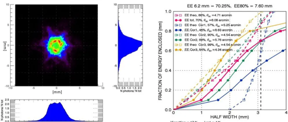
1.0 É w0.8 O ï O.8 IL 0 LL z ó 02 EE 8.2 mm - 70.25%, EE80%= 7.80 mm AO EEOwa.f0oYe-4.71amnT !SE
M EEMAáBe=7GCamnin;d
d 50 EEtlw611.6%.ea=5]uenn % h. EECUf.1OAA..EMam1n... f. .. 0 EE1UC8257Il6m-4E(manln / MEE52+f.Oe-SiBalmin 00 0EE Oho C4A0716.Oa=4%.. oa 1 M. moors.GY6.Ear=9.N d MIS ®e
0.00 1gnabn7-17% 2 HALF WIDTH (mm) aFigure 8 – Left: PSF obtained as composition of the 18 mirrors PSFs realigned to their own barycentre and at a focal distance of 3.7 mm from the theoretical focal plane. The image refers to a squared area of 10x10 mm. The obtained EE value is 83%. Right: decomposition of the EE into contributions from different coronae.
4.1 Note about the realignment
In the theoretical ASTRI SST-2M design the PSF of each mirror covers a precise region of the pixel and the possibility of realigning the single PSFs barycenters to match the centre of the camera is not considered. This is comprehensible because this kind of operation can only be obtained moving the single panels while the optical design is obtained optimizing the parameters of the polynomial describing the mirrors considered as monolithic.
Since we moved the single PSFs to maximize the EE on-axis while the design is optimized to guarantee almost constant EE for off-axis angles lower than 4.5 degrees, we need to verify what happens to the realigned PSF when an off-axis source is observed. To do that we compared the EE of: i) the PSF simulated for the theoretical design (Figure 9 upper row); ii) the PSF obtained realigning the barycenters of each panel PSF to the centre of the camera (Figure 9 lower row) for off-axis angle in the range 0-5 degrees. In figure 9 all images are displayed on squared fields with an area of 10x10 mm.
Figure 9 – Up: PSF of the ASTRI SST-2M theoretical design off-axis. Down: PSF of the ASTRI SST-2M theoretical design off-axis with each panel realigned on its barycentre. The images refer to a source at 0-1-2-3-4-5 degrees off-axis.
Comparing the obtained EE dependences on the off-axis angle we note that the realignment of each panel on its own barycenter causes the EE to worsen for off-axis angles greater than 3 degrees. This change in behaviour is almost completely due to the different focusing of corona 1, that in the theoretical design is defocused when an on-axis source is observed and compensates the corona-2 and corona-3 defocusing for off-axis sources. Realigning the single PSF we obtain higher EE on-axis (> 95%) but rapidly decreasing values for off-axis angle > 3°.
[mm] [m m ]
ASTRI SST-2I I go so 2 s m at 60
off-ads Ensqu&ed Energy
e -e EE tooregmal dawn realigned each panel btuyeentar
EE amanita' design
2 3 4
Off-ads angle WOW
ASTRI SST2M olfaxls Ensquarea Energy
1ST
`ter
w
Ce3EEMe0Y6111iF81Weigh. CatTEErealignedw
Cor 2 EE UneoreMicel deer Coi'2EE realignedw
con EECIeOYEMlpltlesgll Cot EEreangned2
Cflaids angle deg
4
Figure 10 – Left: Comparison between the off-axis total Ensquared Energy of the theoretical design and the one obtained after the realignment of each panel on its barycenter. Right: decomposition in coronae.
5. CONCLUSIONS
In this contribution we presented the characterization of the primary mirror of the ASTRI SST-2M telescope. The mirror surface errors were measured using an ad-hoc deflectometrical facility developed at INAF-OAB to offer an in-house time and cost saving method to qualify free-form mirrors.
The working principle of the deflectometrical test is a synergy between an inverse Ronchi-like test and ray-tracing simulations. The ray-tracing allows the reliability of the measured slope error to be evaluated, by comparing the simulated images with direct illumination pictures. Once the correspondence between the retrieved and directly observed reflected images is verified, the ray-tracing simulation is repeated in telescope configuration and the PSFs at the focal plane are calculated.
We found that all 18 mirrors mounted on the ASTRI SST-2M telescope satisfy the requirement of concentrating 80% of the photons on a squared area of 6.2 mm in side, but due to the different focal length of the three coronae (caused by different spring back effect) the total PSF is strongly degraded. To fix this problem we tested the effect of single mirror realignment discovering that this operation would boost the EE to 83% on-axis by shifting the focal position of 3.7 mm (which is well within in the camera moving range) and it will not suffer degradation up to 3 degrees off-axis.
In any case, because of the difficulties raised by the differences in focal length, we suggest to proceed by steps: the first is to try to fix the focal length error by compensating the effect during the mirror manufacturing process; the second is to consider the possibility to have a piston movement on the dish allowing each mirror to be placed at the correct distance; the third is to consider in any case a realignment procedure (not necessarily the one we proposed), because the improvement of the EE can be highly significant.
ACKNOWLEDGMENTS
This work was partially supported by the ASTRI “Flagship Project” financed by the Italian Ministry of Education, University, and Research (MIUR) and led by the Italian National Institute of Astrophysics (INAF). We also acknowledge partial support by the MIUR Bando PRIN 2009.
We gratefully acknowledge support from the agencies and organizations listed under Funding Agencies at:
http://www.cta-observatory.org/?q=node/22.
REFERENCES
[1] Acharya B. S. et al, “Introducing the CTA concept” Astroparticle Physics 43, 3-18 (2013)
[2] Pareschi G. et al., “The dual-mirror Small Size Telescope for the Cherenkov Telescope Array” Proc. 33rd ICRC 0466 (2013)
[3] Catalano O. et al, “The ASTRI SST-2M Prototype: Camera and Electronics” Proc. 33rd ICRC, 0111, (2013) [4] Cornejo-Rodriguez A., “Ronchi test, in Optical Shop Testing” 3rd ed., D. Malacara, Ed., Wiley Series in Pure
[5] Yatagai T., “Fringe scanning Ronchi test for spherical surfaces“ Applied Optics Vol. 23, N0 20 (1984) [6] Sironi G. et al, “Worthwhile optical method for free-form mirrors qualification” Proc. SPIE 8884 (2013) [7] Knauer M. C. et al., “Phase Measuring Deflectometry: a new approach to measure specular free-form
surfaces” Proc. SPIE 5457, (2004)
[8] Canestrari R., eta al.,Tech. Rep. ASTRI-IR-OAB-3100-009,INAF/OAB (2011)
[9] Vassiliev V. et al., “Wild field aplanatic two-mirror telescopes for ground-based c-array astronomy“ Astroparticle Physics 28 (2007)
[10] Pareschi G. et al., ”Glass mirror by cold slumping to cover 100 m2 of the MAGIC II Cherenkov telescope
reflecting surface” Proc. SPIE 7018 7018W (2008)
[11] Canestrari R., et al., “The ASTRI SST-2M prototype for the Cherenkov telescope array: manufacturing of the structure and of the mirrors” Proc. SPIE 9145-21, (2014)
[12] Canestrari R., et al., “The glass cold-shaping technology for the mirrors of the Cherenkov Telescope Array” Proc. SPIE 9151-102 (2014)
[13] Canestrari R., et al., “Cold-shaping of thin glass foils as novel method for mirrors processing. From the basic concepts to mass production of mirrors” Opt. Eng. 52-5, (2013)