ALMA MATER STUDIORUM - UNIVERSITÀ DI BOLOGNA
SCUOLA DI INGEGNERIA E ARCHITETTURA
DIPARTIMENTO DI INGEGNERIA CIVILE, AMBIENTALE E DEI MATERIALI
CORSO DI LAUREA MAGISTRALE IN CIVIL ENGINEERING
TESI DI LAUREA
in
Advanced Design of Structures
SEMI-ENGINEERED EARTHQUAKE-RESISTANT
STRUCTURES: ONE STORY BUILDINGS MADE WITH
BHATAR CONSTRUCTION TECHNIQUE
CANDIDATO RELATORE:
Raffaele Carabbio Chiar.mo Prof. Ing. Stefano Silvestri
CORRELATORI Dott. Ing. Luca Pieraccini
Anno Accademico 2015/2016
I
ACKNOWLEDGEMENTS
This thesis is focused on an engineering field; at the same time, it has been developed through multidisciplinary knowledge and eyes. The word Design involves all the fields I have ever appreciated. The word Design is the link-word, which connects all my academic path.
Ten years ago I started studying Industrial Design in Architecture atUniversità di Genova, then through the years I crossed civil and environmental studies, finishing focusing on Structural engineering curriculum in Bologna. Often the people thinks this is a strange path but I have never considered myself strictly pure. I have always considered varied and mix knowledge as a wealth.
I would like to thank my supervisor Prof. Ing. Stefano Silvestri, Arch. Martijn Schildkamp, Dot. Ing. Luca Pieraccini; I thank them for the support and time dedicated, for all of their guidance through this process; your discussion, ideas, and feedback have been absolutely invaluable.
I would like to thank Julio Alfredo Samayoa Avalos for his friendship and the time spent together studying and having fun and all my fellow students.
I would like to thank my family for the supports and the economic help for studying so long.
II
SOMMARIO
Questa tesi studia il comportamento statico e sismico di strutture semplici realizzate con un sistema costruttivo utilizzato da vari secoli , in zone piuttosto remote dei paesi che oggi vengono definiti come terzo mondo.A secondo delle zone il nome cambia.Per quanto riguarda le regioni Himalayane tra Nepal e Pakistán il nome comune è Bhatar. Questo sistema costruttivo vede come materiali utilizzati legno e pietra locali. Il Bhatar è costituito da pareti portanti composte da strati di pietra non perfettamente uniforme, i comuni muretti a secco, intervallati orizzontalmente da travi composte da elementi lignei i quali incastrati tra di loro risultano paragonabili a cordoli.Il sistema Bhatar è conosciuto come intrínsecamente antisísmico poichè esistono costruzioni di alcuni secoli che hanno resistito a fenomeni sismici importanti. Le analisi sono condotte con riferimento ad un edificio ad un piano, di dimensioni (pianta 3.60m x 3.6m) e con tetto in legno e terra. Questa tecnologia costruttiva, di carattere semi-ingegneristico, è già ampiamente utilizzata nelle regioni Himalayane, in Pakistan e India, ma è anche indirizzata alle popolazioni di nazioni in via di sviluppo poiché offre un vantaggio sia di tipo economico che di tipo tecnico rispetto ai materiali convenzionali (muratura in mattoni e cemento). Le informazioni ad oggi disponibili su questo genere di strutture sono molto limitate a causa della scarsa e poco approfondita ricerca eseguita sul tema.Di grande utilità è stato il materiale elaborato dall’architetto Tom Schacher technical advisor per la Swiss Agency for Development and Cooperation.Tom Schacher col suo lavoro ha stilato delle linee guida, tramite immagini per popolazioni semi-analfabete, che consigliano particolari dimensionamenti e rapporti tra dimensioni nella costruzione di sistemi a Bhatar.
L’obiettivo principale di questa ricerca è di definire gli aspetti principali del comportamento sismico di un edificio ad un piano composto secondo le linee guida dettate da Tom Schacher, con scopo di prevenire crolli causati da azioni sismiche e quindi ridurre il rischio sismico in quelle regioni del mondo dove questi disastri hanno intensità significative. Non esistono attualmente in letteratura ricerche specifiche su pareti costruite con il sistema Bhatar.
Per quanto riguarda le pareti , sono stati effettuati calcoli e analisi allo scopo di capire il
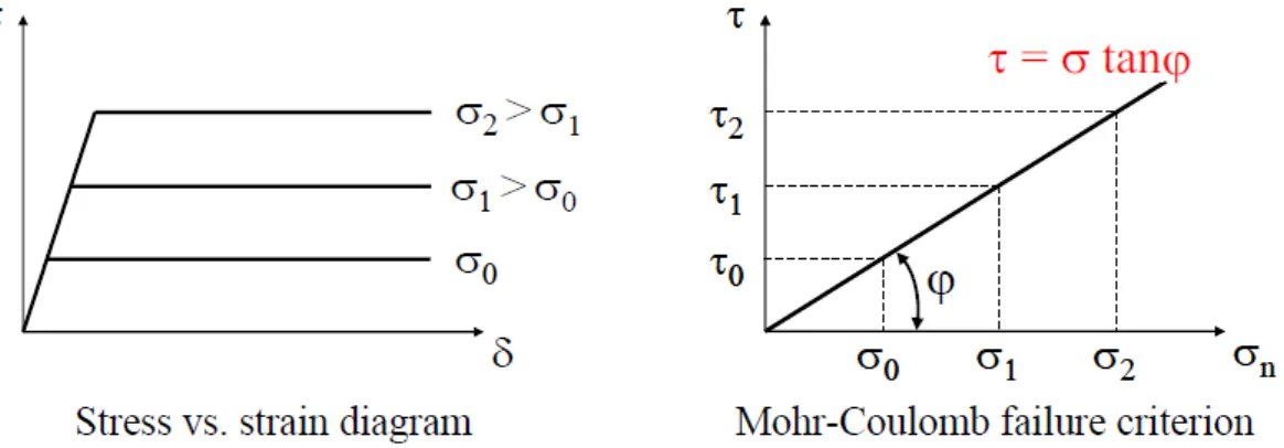
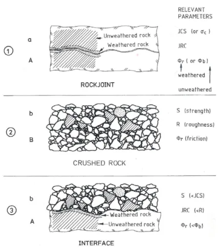
comportamento statico e sismico. In analisi statica, è stata condotta una verifica a sforzo normale calcolando lo sforzo normale agente alla base del muro e la corrispondente capacità resistente.Per quanto riguarda l’analisi sismica del muro, si è studiato sia il comportamento nel piano sia quello fuori dal piano. Per l’analisi in piano ci si è concentrati sul materiale roccioso ed è stato utilizzato il modello di Barton che definisce la relazione non lineare che tra le tensioni normali e tangenziali nelle discontinuità degli ammassi rocciosi in presenza di pietre non uniformi.Per quanto riguarda l’analisi fuori dal piano l’attezione è stata rivolta alle connessioni degli elementi lignei che
diventano fondamentali nelle reazioni a sollecitazioni di tipo orizzontale e prevengono ribaltamento e gli altri meccanismi di collasso, questo scopo le connessioni e le strutture in legno suggerite da Tom Schacher sono state esaminate alla luce delle norme tecniche Eurocodice 5 : Design of timber structures.
Grazie alle analisi effettuate è possibile avere una prima idea di quanto questo tipo di costruzioni siano effettivamente antisismiche. Importante è sottolineare che questa tesi è l’inizio di un lungo lavoro che per essere affrontato al meglio necessita di prove di laboratorio su materiali e prove di laboratorio su modelli in scala reale.
III
ABSTRACT
After the 2005 M7.6 Kashmir earthquake (Pakistan), field observations reported that several buildings manufactured with traditional techniques well resisted to this strong seismic event. Nonetheless, these techniques have never been deeply studied from a structural engineering point of view yet. The high number of people living in such structures highlights the importance of focusing on this subject.
This paper reports a full analytical study on the static and seismic behavior of simple one-storey buildings made with a typical construction technique commonly named as “Bhatar” system, used for several centuries and widely diffused in rather remote areas of the Himalayan regions like India, Nepal and Pakistan.
The Bhatar system consists of load-bearing walls made of common dry-stacked rubble stone masonry held together by horizontal wooden bands disposed at several levels (spaced at intervals of about 60 cm). It is widely adopted in developing countries due to its advantages from both economical and constructive point of view with respect to the conventional constructions techniques (i.e. brick masonry and concrete structures).
Despite its wide diffusion, the information currently available on the actual static and seismic behavior of such construction technique are very limited due to little attention paid on such topic.
In the present work, analytical analyses are conducted with reference to a one-storey building modulus characterized by a 3.6 m x 3.6 m square plan covered by an heavy wooden roof with 20 cm thick earth coverage, in order to investigate its response under both gravity and seismic inertial loadings. In detail, in-plane and out-of-plane response of a single wall under horizontal actions is discussed and particular attention is focused on the connections between the timber elements, which are fundamental for the transmission of the horizontal actions and for preventing overturning and other failure mechanisms.
The main aim is twofold: (i) to provide a first insight into the actual seismic response of such construction technique, as a basis for the specific design of ad-hoc laboratory tests on full-scale models, and (ii) to give some rules of thumb for a proper dimensioning and construction of this kind of structures.
IV
INDEX
ACKNOWLEDGEMENTS ... I SOMMARIO ... II ABSTRACT ... III INDEX ... IV LIST OF FIGURES ... XI LIST OF TABLES ... XVIII SIMBOLOGY ... XX1 INTRODUCTION ... 1
1.1 Background ... 1
1.2 Justification of the document and objectives ... 1
1.2.1 General objectives ... 2
1.2.2 Specific objectives ... 2
1.3 Organization of the thesis ... 2
2 BHATAR ... 2
2.1 Traditional definition of Bhatar ... 2
2.2 Tom Schacher Manual : Bhatar construction - An illustrated guide for craftsmen ... 4
2.2.1 Gross shape and dimensions ... 4
2.2.2 Foundation and plinth band... 5
2.2.3 The Walls ... 5
2.2.4 Wall - joints ... 6
2.2.5 Kashmiri joint or Keyed scarf joint... 7
2.2.6 Connections - Corners ... 7
2.2.7 Connections – Cross Pieces ... 8
2.2.8 Connections – Internal wall ... 8
2.2.9 Openings ... 9
2.2.10 Doors ... 9
2.2.11 Windows ... 10
2.2.12 The Roof ... 10
3 STUDY CASE ... 11
3.1 Single modular unit ... 11
3.1.1 Orthogonal projection ... 12
V
3.2.1 Orthogonal projection ... 13
3.3 One room box ... 14
3.3.1 Orthogonal projection ... 15
3.3.2 The Roof ... 16
4 MATERIALS ... 18
4.1 Timber : Shorea Robusta ... 18
4.1.1 Botanic Characteristics ... 18
4.1.2 Mechanical properties of Shorea Robusta ... 18
4.1.3 Characteristic Values from EN 338 ... 19
4.1.4 Design Values from EC 5 and en.1995.1.1.2004 and NICOLE – Istruzioni CNR_DT206_2007 ... 20
4.2 Stones : Main construction material since the Stone Age ... 20
4.2.1 Limestone mechanical properties... 22
5 BARTON MODEL AND SHEAR STRENGTH OF ROCKFILL ... 26
5.1 Interfaces between material : Timber-Stone and Stone-Stone ... 26
5.2 Shear strength of rock discontinuities ... 28
5.3 Plane smooth joint ... 28
5.4 Idealised rough joint (Patton , 1966) ... 29
5.5 Real rough joint (Barton, 1973) ... 31
5.5.1 Barton’s failure criterion ... 32
5.5.2 Barton’s empirical model: ... 32
5.6 Shear Strength of Rockfill ... 37
5.6.1 The shear strength of rockfill as measured ... 38
5.6.2 Estimating the shear strength of rockfill ... 41
5.6.3 Interface shear strength ... 42
5.6.4 R-controlled or JRC-controlled behavior ... 44
5.7 Barton model applied on Bhatar system... 44
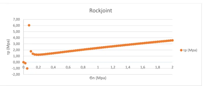
5.7.1 Rockjoint ... 45
5.7.2 Rockfill... 45
5.7.3 Voids ratio and Porosity ... 46
5.7.4 Limestone Mechanical Properties for application of Barton model ... 47
5.7.5 Rockjoint results ... 48
5.7.6 Rockfill results ... 50
VI
6 TIMBER ELEMENTS AND CARPENTRY CONNECTIONS ... 54
6.1 Geometry of Timber elements ... 54
6.1.1 Rafter ... 55
6.1.2 Roof rafter ... 56
6.1.3 Cross piece ... 57
6.2 Assembling ... 58
6.2.1 Timber Band ... 58
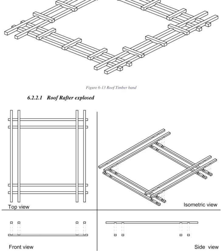
6.2.2 Roof Timber Band ... 60
6.3 Portions of Rafter and Roof rafter ... 62
6.3.1 Rafter Head + Rafter Body + Rafter Head ... 62
6.3.2 Roof Rafter Head + Rafter Body + Roof Rafter Head ... 62
6.3.3 Subdivisions of the timber elements ... 63
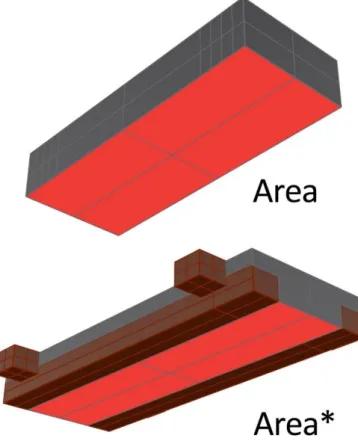
6.4 Area under stresses ... 64
6.4.1 Cross Piece ... 64
6.4.1 Rafter ... 64
6.4.2 Roof Rafter ... 65
6.4.3 Measures for area under stresses ... 66
6.5 Saint Venant for Timber elements ... 67
6.5.1 Rafter ... 67
6.5.2 Roof rafter ... 70
6.5.3 Cross piece ... 73
6.6 Eurocode 5 : EN 1995-1-1 :2004+A 1 ... 76
6.6.1 Tension parallel to the grain ... 76
6.6.2 Tension parallel to the grain with keyed scarf joint ... 76
6.6.3 Compression parallel to the grain ... 76
6.6.4 Compression perpendicular to the grain ... 77
6.6.5 Tension perpendicular to the grain... 77
6.6.6 Bending ... 77
6.6.7 Shear... 78
6.6.8 Torsion ... 79
6.6.9 Combined bending and axial tension ... 80
6.6.10 Combined bending and axial compression ... 81
6.6.11 Combined Torsion and Shear - CNR-DT 206/2007 ... 82
VII
6.7.1 Longitudinal to the grain ... 83
6.8 Resistances - Cross piece Notch ... 85
6.8.1 Longitudinal to the grain ... 85
6.9 Activation of the chains ... 87
6.9.1 Overturning Mechanism ... 88
6.9.2 Activation of the chain along Roof Rafter Head ... 90
6.9.3 Activation of the chain along Rafter Head ... 111
6.9.1 Possible actions along cross pieces ... 131
6.10 Internal developed bending moments ... 141
6.10.1 Mytf bending moment due to tension ... 141
6.10.2 Mycf bending moment due to compression ... 142
6.10.3 Mz bending moment ... 143
6.10.4 Torsional Mx ... 144
6.11 Keyed scarf joint ... 146
6.11.1 Geometry and resistance ... 146
6.11.2 Influence of keyed scarf joint on element subjected to tension ... 147
7 STATIC ANALYSIS ... 148
7.1 Aim of static analysis ... 148
7.2 Single modular unit ... 148
7.2.1 Material properties ... 148
7.2.2 Volumes ... 148
7.2.3 Weights and stresses ... 150
7.1 Roof ... 150
7.1.1 Material properties ... 150
7.1.2 Volumes ... 151
7.1.3 Weights and linear load... 151
7.2 Normal Stresses ... 152
7.2.1 Normal Stress inside stones layer ... 153
7.2.2 Normal Stress below timber beam ... 154
8 SEISMIC ANALYSIS IN PLANE ... 156
8.1 Shear strength for rockfill with Barton empirical model ... 156
8.1.1 Normal Stress and Coefficients of friction inside stones layer ... 156
8.1.2 Normal Stress and Coefficients of friction below timber beam ... 157
VIII
8.2.1 Critical multiplier for inside stones layer ... 157
8.2.2 Critical Multiplier below the timber band... 165
8.2.1 Conclusions on seismic analysis in-plane ... 170
9 SEISMIC ANALYSIS OUT OF PLANE – OVERTURNING RIGID BEHAVIOR ... 174
9.1 Hypothesis of rigid body behavior ... 174
9.2 Rigid body over rigid soil by Equilibrium – Tmin as function of α load multiplier - Hand calculation ... 175
9.2.1 Horizontal equilibrium ... 176
9.2.2 Rotational equilibrium ... 177
9.3 Rigid body over rigid soil by PVW - α load multiplier - Hand calculation ... 179
9.3.1 Unique seismic force on the top ... 180
9.3.2 Roof force + Wall force ... 183
9.3.3 Unique seismic force on the top with timber tie-beams - Minimum Tension dependent on α 185 9.3.4 Roof force + Wall force with timber tie-beams - Minimum Traction dependent on α 188 9.4 Conclusions about the highest required tension strength Tmin ... 191
9.4.1 Horizontal equilibrium and Rotational equilibrium – Tmin ... 191
9.4.2 Unique seismic force on the top - α critical ... 192
9.4.3 Roof force + Wall force - α critical ... 192
9.4.4 Unique seismic force on the top with timber tie-beams - Tmin ... 193
9.4.5 Roof force + Wall force with timber tie-beams - Tmin ... 193
9.5 Verifications for Overturning Rigidbehavior ... 194
9.5.1 Analyzing the worst case : Unique seismic force on the top with timber tie-beams - Tmin 194 9.5.2 Equal distribution of the reactions T1=T2 and R1=R2 ... 194
9.5.3 Verifications T1=T2 ... 196
9.5.4 Verifications R1=R2 ... 199
9.5.5 Verifications on corner joint, seismic event parallel to Roof Rafter ... 201
9.5.6 Verifications on corner joint, seismic event parallel to Rafter ... 206
9.6 Conclusions on seismic analysis out of plane – Overturning ... 208
9.6.1 Safetybehavior under seismic multiplier α=0,15 ... 208
10 SEISMIC ANALYSIS OUT OF PLANE - FLEXIBLE RESPONSE BENDING BEHAVIOR 210 10.1 Hypothesis of Flexible response – Bending behavior ... 210
IX
10.1.1 Hypothesis of Flexible behavior ... 211
10.1.2 Static scheme of the timber tie- beam ... 211
10.1.3 Hyperstatic scheme of the corner joint and actions from static scheme of the timber tie- beam ... 213
10.1.4 Hyperstatic rigid-jointed frame ... 213
10.2 Force method with Müller-Breslau equations ... 215
10.2.1 Force method... 215
10.2.2 Degree of indeterminacy Rigid-Jointed Frame ... 215
10.2.3 Solved released systems ... 217
10.2.4 Functions of the diagrams ... 222
10.2.5 Müller-Breslau equations ... 222
10.2.6 Solutions of the complete isostatic structure... 229
10.3 Triangular distribution of seismic load 𝒒𝜶 ... 232
10.3.1 Scheme of wall Flexible response – Bendingbehavior ... 232
10.3.2 Masses involved and heights of each timber beam ... 233
10.3.3 Seismic load 𝒒𝜶 and Distribution factor 𝜷𝒋 ... 233
10.4 Reactions for each beam ... 235
10.4.1 Rafter body reactions for each beam in the corner joint ... 235
10.4.2 Rigid- jointed frame reactions for each beam ... 236
10.4.3 T1 in compression & T2 in tension ... 238
10.5 Verifications for Flexible response – Bendingbehavior ... 240
10.5.1 Analyzing the worst case : Roof level with maximum Seismic load 𝑞𝛼 (α=1) ... 240
10.5.2 Distribution of the reactions T1≠T2 and R1=R2 ... 240
10.5.3 Verifications T1 - compression ... 241
10.5.4 Verifications T2 - tension ... 243
10.5.5 Verifications R1=R2 ... 244
10.5.6 Verifications on corner joint, seismic event parallel to Roof Rafter ... 248
10.5.7 Verifications on corner joint, seismic event parallel to Rafter ... 264
10.6 Conclusions on seismic analysis out of plane – Flexible ... 267
10.6.1 Safetybehavior under seismic multiplier α=0,125 ... 267
11 PRACTICAL RULES OF THUMB FOR CONSTRUCTION OF BHATAR SYSTEM ... 268
11.1 Arch Tom Schacher’s rule of thumb an new specifications ... 268
11.1.1 Specifications on wall joints ... 268
X
11.2.1 Consideration about vertical component of the seismic event, ... 270
11.2.2 Steel wire connectors ... 270
11.2.1 Vertical rafters ... 279
11.2.2 Roof timber band ... 282
12 CONCLUSIONS ... 284
12.1 Analysis performed ... 284
12.2 Results... 285
12.2.1 Results on seismic analysis in-plane ... 285
12.2.2 Results on seismic analysis out of plane ... 287
12.3 Possible research developemnts ... 289
BIBLIOGRAPHY ... 290
XI
LIST OF FIGURES
Figure 2-1 Project entry 2008 Asia Pacific - "Advocacy of traditional earthquake-resistant
construction, North-West Frontier Province, Pakistan": “Bhatar” at Besham Fort. ... 2
Figure 2-2 Regions of the world where Bhatar is still used ... 3
Figure 2-3 Nepal peak ground acceleration ... 3
Figure 2-4 Bhatar construction-An illustrated guide for craftsmen ... 4
Figure 2-5 Divided rectangular structures ... 4
Figure 2-6 Gross dimension - ratio length/width... 5
Figure 2-7 Foundations ... 5
Figure 2-8 The plint ... 5
Figure 2-9 Wall dimensions ... 6
Figure 2-10 Spread the connection points. ... 6
Figure 2-11 Raise all walls together to avoid vertical joints ... 7
Figure 2-12 Kashmiri joint or Keyed Scarf Joint ... 7
Figure 2-13 minimum size of the beams/rafters ... 7
Figure 2-14 Lap joint – dimension ... 8
Figure 2-15 Cross Pieces... 8
Figure 2-16 Internal wall joint ... 9
Figure 2-17 Openings ... 9
Figure 2-18 Openings 2 ... 9
Figure 2-19 Lintel reinforcement ... 10
Figure 2-20 the flat heavy roof with earth cover ... 10
Figure 3-1 Modular unit-perspective ... 11
Figure 3-2 Modular unit - Orthogonal projection in cm ... 12
Figure 3-3Largest wall possible , length of 3.6m ... 13
Figure 3-4 Wallt - Orthogonal projection in cm ... 13
Figure 3-5 One room box ... 14
Figure 3-6 One room box orthogonal projections in cm ... 15
Figure 3-7 Section AA - studied wall ... 16
Figure 3-8 Flat earth heavy roof – exploded ... 17
Figure 4-1 Shorea Robusta – SAL ... 18
Figure 4-2 Architect Martijn Schildkamp - bhatar stones ... 21
Figure 4-3 Sedimentary rocks ... 21
Figure 4-4 Limestone/Calcarea ... 22
Figure 5-1 Stone layer (black box above) - Timber beam (black box below) ... 26
Figure 5-2 Contact surfaces ... 27
Figure 5-3 Plane and smooth joint surface ... 28
XII
Figure 5-5 Rough joint surface ... 29
Figure 5-6 45-D0566/A Profilometer (Barton comb), 150 mm length. ControlsGroup... 32
Figure 5-7 Roughness profiles and their corresponding JRC values (Barton and Choubey 1977) .... 33
Figure 5-8 Tilt test (or self-weight gravity shear test) for characterizing rock joints. Note measurement ... 33
Figure 5-9 Tilt Test apparatus ... 34
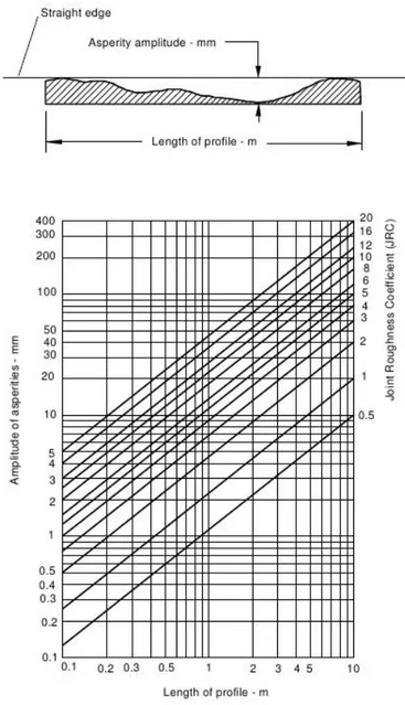
Figure 5-10 Alternative method for estimating JRC from Measuremens of surface roughness amplitude from a straight edge (Barton 1982). ... 35
Figure 5-11 Estimate of joint wall compressive strength from Schmidt hardness ... 36
Figure 5-12 When peak shear strength is approached (joints and rockfill), the actual rock-to-rock contact stress levels are extremely high, due to small contact areas. ... 37
Figure 5-13 Illustration of the tilt test principle for rockfill (Barton and Kjærnsli, 1981) ... 38
Figure 5-14 Leps ( 1970) ... 38
Figure 5-15 The peak shear strength envelopes for rockfill have remarkable similarity to those for medium rough, medium strength rock joints. Large-scale test data from Marsal (1973) ... 39
Figure 5-16 Large rock dumps are a familiar feature of mines in the Chilean Andes. Large-scale triaxial shear tests performed in Chile, with important results (black dots and Mohr circles) showing non-linear stress- ependent friction angles (Linero and Palma 2006) ... 40
Figure 5-17 The same non-linearity with effective stress level is seen in large-scale triaxial tests performed at NGI (Strøm, 1974, 1975, 1978), with particle size-dependence, rock strength dependence, and porosity effects also indicated ... 40
Figure 5-18 Shear strength envelopes (and peak dilation angles) predicted for rock joints, using the JRC-JCS non-linear model of Figure 5-10. Rockfill generally lies between curves #2 and #3 ... 41
Figure 5-19 An empirical method for estimating the equivalent roughness R of rockfill as a function of porosity and particle origin, roundedness and smoothness. Barton and Kjærnsli (1981) ... 41
Figure 5-20 Particle size strongly effects the strength of contacts points in rockfill. Triaxial or plane shear also influencesbehavior. Empirical S/UCS reduction factors for estimating S when evaluating equation 3. ... 42
Figure 5-21 Asperity contact across stressed rock joints, and rockfill inter-particle contact, and rockfill lying on a rock foundation. ... 43
Figure 5-22 A review of interface shear tests was performed in response to concern over insufficient roughness for the rockfill dam foundation, in the glaciated mountain terrain in Norway. ... 44
Figure 5-23 Rockjoint function for Bhatar ... 49
Figure 5-24 Rockjoint function for Bhatar range of interest ... 49
Figure 5-25 Rockfill function for Bhatar ... 51
Figure 5-26 Rockfill function for Bhatar range of interest ... 52
Figure 6-1 Continuous Bhatar wall ... 54
Figure 6-2 Carpentery connections ... 54
Figure 6-3 Rafter beam ... 55
XIII
Figure 6-5 Roof rafter beam... 56
Figure 6-6 Roof rafter beam Orthogonal projections in cm ... 56
Figure 6-7Cross piece ... 57
Figure 6-8 Cross Piece Orthogonal projections in cm ... 57
Figure 6-9 Timber Band ... 58
Figure 6-10 Timber band Rafter exploded ... 58
Figure 6-11 Timber band Cross pieces exploded ... 59
Figure 6-12 Timber band All exploded ... 59
Figure 6-13 Roof Timber band ... 60
Figure 6-14Roof timber band Roof rafter exploded ... 60
Figure 6-15 Roof timber band Cross pieces exploded ... 61
Figure 6-16 Roof Timber band All exploded ... 61
Figure 6-17 6.3.1 Rafter Head + Rafter Body + Rafter Head ... 62
Figure 6-18 6.3.2 Roof Rafter Head + Rafter Body + Roof Rafter Head ... 62
Figure 6-19 Subdivisions of the timber elements ... 63
Figure 6-20 Area under stresses - Cross piece ... 64
Figure 6-21 Area under stresses - Rafter ... 64
Figure 6-22 Area under stresses - Roof Rafter ... 65
Figure 6-23 All areas under stresses ... 66
Figure 6-24 Rafter -Compression along X axis ... 67
Figure 6-25 Rafter -Tension along X axis ... 67
Figure 6-26 Rafter -Shear on Y axis ... 68
Figure 6-27 Rafter -Shear on Z axis ... 68
Figure 6-28 Rafter - Bending Moment My on Y axis ... 69
Figure 6-29 Rafter - Bending Moment Mz on Z axis ... 69
Figure 6-30 Rafter - Torsion: Mx on x axis ... 69
Figure 6-31 Roof Rafter -Compression along X axis ... 70
Figure 6-32 Roof Rafter -Tension along X axis ... 70
Figure 6-33 Roof Rafter -Shear on Y axis ... 71
Figure 6-34 Roof Rafter -Shear on Z axis ... 71
Figure 6-35 Roof Rafter - Bending Moment My on Y axis ... 72
Figure 6-36 Roof Rafter - Bending Moment Mz on Z axis ... 72
Figure 6-37 Roof Rafter - Torsion: Mx on x axis ... 72
Figure 6-38 Cross Piece -Compression along X axis ... 73
Figure 6-39 Cross Piece -Tension along X axis ... 73
Figure 6-40 Cross Piece -Shear on Y axis ... 74
Figure 6-41 Cross Piece -Shear on Z axis ... 74
Figure 6-42 Cross Piece -Bending Moment My on Y axis ... 75
Figure 6-43 Cross Piece -Bending Moment Mz on Z axis ... 75
Figure 6-44 Cross Piece -Torsion: Mx on x axis ... 75
XIV
Figure 6-46 (a) Member with a shear stress component parallel to the grain (b) Member with both
stress components perpendicular to the grain (rolling shear) ... 79
Figure 6-47 Torsional stress distribution ... 80
Figure 6-48 Combined bending with axial compression/tension ... 81
Figure 6-49 Combined biaxial bending with axial compression/tension : ... 81
Figure 6-50 Overview of the room box ... 88
Figure 6-51Section of the studied wall ... 88
Figure 6-52 Overturning mechanism ... 89
Figure 6-53Overturning mechanism - Orthogonal projections ... 89
Figure 6-54 - activation of the chains Overturning mechanism ... 90
Figure 6-55 Figure 6 53Overturning mechanism - Orthogonal projections activation of the chains 90 Figure 6-56 Roof timber beam subjected to seismic actions ... 91
Figure 6-57 Repartitions of forces - Roof timber beam subjected to seismic actions ... 91
Figure 6-58 Descriptions of the rafters crossed at the roof timber beam ... 92
Figure 6-59 Description of the crossing rafters at roof level ... 92
Figure 6-60 Roof Rafter Head Axial stresses : Crossing rafters T2-R2 ... 94
Figure 6-61 Roof Rafter Head Axial stresses : Crossing rafters T1-R1 ... 95
Figure 6-62 Roof Rafter Head Axial stresses : Crossing rafters T1-R2 ... 96
Figure 6-63 Roof Rafter Head Axial stresses : Crossing rafters T2-R1 ... 97
Figure 6-64 Roof Rafter Head Tangential stresses: Crossing rafters T2-R2 ... 99
Figure 6-65 Roof Rafter Head Tangential stresses: Crossing rafters T1-R1 ... 100
Figure 6-66 Roof Rafter Head Tangential stresses: Crossing rafters T1-R2 ... 101
Figure 6-67 Roof Rafter Head Tangential stresses: Crossing rafters T2-R1 ... 102
Figure 6-68 Roof Rafter Head Bending moments: Axial stresses: Crossing rafters T2-R2 ... 103
Figure 6-69 Roof Rafter Head Bending moments: Axial stresses: Crossing rafters T1-R1 ... 104
Figure 6-70 Roof Rafter Head Bending moments: Axial stresses: Crossing rafters T1-R2 ... 105
Figure 6-71 Roof Rafter Head Bending moments: Axial stresses: Crossing rafters T2-R1 ... 106
Figure 6-72 Roof Rafter Head Bending moments: Torsnion : Tangential stresses : Crossing rafters T2-R2 ... 107
Figure 6-73 Roof Rafter Head Bending moments: Torsion: Tangential stresses: Crossing rafters T1-R1 ... 108
Figure 6-74 Roof Rafter Head Bending moments: Torsion: Tangential stresses: Crossing rafters T1-R2 ... 109
Figure 6-75 Roof Rafter Head Bending moments: Torsion: Tangential stresses: Crossing rafters T2-R1 ... 110
Figure 6-76 Roof timber beam subjected to seismic actions (normal rafter) ... 111
Figure 6-77 Repartitions of forces - Roof timber beam subjected to seismic actions (normal rafter) ... 111
Figure 6-78 Descriptions of the rafters crossed at the roof timber beam actions (normal rafter) . 112 Figure 6-79 Description of the crossing rafters at roof level actions (normal rafter) ... 112
Figure 6-80 Rafter Head Axial stresses: Crossing rafters T2-R2 ... 114
XV
Figure 6-82 Rafter Head Axial stresses: Crossing rafters T1-R2 ... 116
Figure 6-83 Rafter Head Axial stresses: Crossing rafters T2-R1 ... 117
Figure 6-84 Rafter Head Tangential stresses: Crossing rafters T2-R2 ... 119
Figure 6-85 Rafter Head Tangential stresses: Crossing rafters T1-R1 ... 120
Figure 6-86 Rafter Head Tangential stresses: Crossing rafters T1-R2 ... 121
Figure 6-87 Rafter Head Tangential stresses: Crossing rafters T2-R1 ... 122
Figure 6-88 Rafter Head Bending moments: Axial stresses: Crossing rafters T2-R2 ... 123
Figure 6-89 Rafter Head Bending moments: Axial stresses: Crossing rafters T1-R1 ... 124
Figure 6-90 Rafter Head Bending moments: Axial stresses: Crossing rafters T1-R2 ... 125
Figure 6-91 Rafter Head Bending moments: Axial stresses: Crossing rafters T2-R1 ... 126
Figure 6-92 Rafter Head Bending moments: Torsnion : Tangential stresses : Crossing rafters T2-R2 ... 127
Figure 6-93 Rafter Head Bending moments: Torsion: Tangential stresses: Crossing rafters T1-R1 128 Figure 6-94 Rafter Head Bending moments: Torsion: Tangential stresses: Crossing rafters T1-R2 ... 129
Figure 6-95 Rafter Head Bending moments: Torsion: Tangential stresses: Crossing rafters T2-R1 ... 130
Figure 6-96 Cross Piece – Compression ... 131
Figure 6-97 Cross Piece - Compression - Axial stresses ... 132
Figure 6-98 Cross Piece - Compression - Tangential stresses ... 133
Figure 6-99 Cross Piece – Tension... 134
Figure 6-100 Cross Piece - Tension - Axial stresses ... 136
Figure 6-101 Cross Piece - Tension - Tangential stresses ... 137
Figure 6-102 Cross Piece – Friction/Inertia ... 138
Figure 6-103 Cross Piece - Friction/Inertia - Axial stresses ... 139
Figure 6-104 Cross Piece - Friction/Inertia - Tangential stresses... 140
Figure 6-105 Parasitic Bending moment along Y axis due to tension and flexion ... 141
Figure 6-106 Parasitic Bending moment along Y axis due to compression and flexion ... 142
Figure 6-107 Parasitic Bending moment along Z axis due to compression and flexion ... 143
Figure 6-108 Parasitic Torsional Bending moment along X axis due to compression on the notch144 Figure 6-109 Parasitic Torsional Bending moment along X axis due to compression on the body section ... 145
Figure 6-110 Figure 6 109 Parasitic Torsional Bending moment along X axis due to Friction/Inertia case on the body section ... 146
Figure 6-111 Kashmir Joint or Keyed Scarf Joint ... 146
Figure 7-1 Single modular unit – Decomposed ... 149
Figure 7-2 Single modular unit – Large -Decomposed ... 149
Figure 7-3 Roof – Decomposed ... 151
Figure 7-4 Normal stresses - Inside stones layers - Studied surfaces Figure 7-5 Normal stresses - Inside stones layers - Sigma Stresses 153 Figure 7-6 Normal stresses - Below timber beam - Sigma Stresses Figure 7-7 Normal stresses - Below timber beam - Studied surfaces ... 154
XVI
Figure 8-1 Analyzed layers for inside stones layer case ... 157
Figure 8-2 Force applied at the top of the wall ... 158
Figure 8-3 Triangular lateral distribution over the height of the wall for inside stones layer ... 159
Figure 8-4 Triangular lateral distribution over the height of the wall for inside stones layer- Heights (cm) ... 160
Figure 8-3 Uniform lateral distribution over the height of the wall for inside stones layer ... 162
Figure 8-5 Analyzed layers for the below timber bands case ... 165
Figure 8-6 Triangular lateral distribution over the height of the wall for below timber bands ... 166
Figure 8-7 Triangular lateral distribution over the height of the wall for below timber bands - Heights ... 166
Figure 8-6 Triangular lateral distribution over the height of the wall for below timber bands ... 168
Figure 8-8 Critical layers for the in-plane seismic analysis ... 171
Figure 9-1 Overturning mechanism – example scheme ... 174
Figure 9-2 Overturning mechanism - tie-timber beam chains activation ... 174
Figure 9-3 Heights of the rafters and distances between the timber beams bands ... 176
Figure 9-4 Horizontal equilibrium – equilibrium method ... 176
Figure 9-5 Rotational equilibrium – equilibrium method ... 178
Figure 9-6 Hinges posotions Figure 9-7 Hinges heights and Blocks Heights ... 180
Figure 9-8 Unique seismic force on the top - Overturning Wall - α critical ... 181
Figure 9-9 Unique seismic force on the top - Overturning Blocks - α critical ... 182
Figure 9-10 Roof force + Wall force - Overturning Wall - α critical ... 183
Figure 9-11 Roof force + Wall force - Overturning Blocks - α critical ... 184
Figure 9-12 Unique seismic force on the top - Overturning Wall - Tmin... 186
Figure 9-13 Unique seismic force on the top - Overturning Blocks - Tmin ... 187
Figure 9-14 Roof force + Wall force - Overturning Wall - Tmin ... 189
Figure 9-15 Roof force + Wall force - Overturning Blocks – Tmin ... 190
Figure 9-16 Overturning - RH90Shear most critical section ... 208
Figure 10-1 Flexible mechanism – example scheme ... 210
Figure 10-2 Flexible mechanism - tie-timber beam chains activation ... 211
Figure 10-3 Flexible mechanism - deformed tie-timber beam chains and activation ... 211
Figure 10-4 Static scheme of the timber tie-beam (clamped ends) ... 212
Figure 10-5 Hyperstatic scheme of the corner joint and actions from static scheme of the timber tie- beam ... 213
Figure 10-6 Hyperstatic rigid-jointed frame ... 214
Figure 10-7 Rigid-Jointed Frame - names of the corners ... 215
Figure 10-8 Primary structure - Static system ... 216
Figure 10-9 Decomposition of the redundant frame... 216
Figure 10-10 System 0 Figure 10-11 External Equilibrium System "0" ... 217
Figure 10-12 Internal Equilibrium System "0" ... 217
Figure 10-13 Internal reactions System "0" ... 218
Figure 10-14 System 1 Figure 10-15 External Equilibrium System "1" ... 218
XVII
Figure 10-17 Internal Reactions System "1" ... 219
Figure 10-18 System 2 Figure 10-19 External Equilibrium System "2" ... 219
Figure 10-20 Internal Equilibrium System "2" ... 220
Figure 10-21 Internal Reactions System "2" ... 220
Figure 10-22 System "3" Figure 10-23 External Equilibrium System "3" ... 220
Figure 10-24 Internal Equilibrium System "3" ... 221
Figure 10-25 Internal reactions System "3" ... 221
Figure 10-26 Flexible response – Bendingbehavior - Analyzed beams ... 232
Figure 10-27 Bending behavior Pertinent masses for each timber band Figure 10-28 Bending behavior Heights of each timber band ... 233
Figure 10-29 Bending behavior -Distribution factors ... 234
Figure 10-30 Bending behavior - Rigid- jointed frame reactions for each beam- ... 236
Figure 10-31 Bending behavior - Rigid- jointed frame reactions for each beam - Resisting rafters R ... 237
Figure 10-32 Bending behavior - Distribution of the forces on the rafters ... 238
Figure 10-33 Bending behavior - Distribution of the forces on the rafters- corner joint ... 238
Figure 10-34 Rigid-Jointed Frame - names of the corners- scheme ... 248
Figure 10-35 Flexible - RH90Shear most critical section... 267
Figure 11-1 Spread the connection points. ... 268
Figure 11-2 Pattern of Keyed scarf joint (or Kashmir joint) ... 269
Figure 11-3Pattern for internal and external surface of the same wall ... 269
Figure 11-4 Forces acting on the steel wire connectors ... 270
Figure 11-5 Pattern of vertical fasten connector ... 271
Figure 11-6 Example of single diagonal connector with positive orientation ... 272
Figure 11-7 Example of single diagonal connector with negative orientation ... 272
Figure 11-8 Preliminary design of diagonal connectors ... 273
Figure 11-9 Connectors for foundation ... 276
Figure 11-10 Vertical connectors total wall - external ... 277
Figure 11-11 Vertical connectors total wall - internal ... 278
Figure 11-12 Connectors on total wall - external ... 278
Figure 11-13 Vertical Rafters – gross measuraments in cm ... 279
Figure 11-14 Connectors for vertical rafters. ... 279
Figure 11-15 Thrifty Solution orthogonal projections ... 280
Figure 11-16 Thrifty solution ... 280
Figure 11-17 Optimal sSolution orthogonal projections ... 281
Figure 11-18 Optimal solution ... 281
Figure 11-19 Rule of thumb for the roof... 282
Figure 11-20 Rule of thumb for the roof - Timber band at roof level exploded ... 283
Figure 12-1 Critical layers for the in-plane seismic analysis. Sliding ... 286
Figure 12-1 Critical layers for the in-plane seismic analysis. Sliding ... 286
Figure 12-2 Critical sections on the bhatar construction ... 288
XVIII
LIST OF TABLES
Table 1 Shorea Robusta mechanical properties 1 ... 19
Table 2 Shorea Robusta mechanical properties 2 ... 19
Table 3 Design Value EC5-Nicole -1 ... 20
Table 4 Design Value EC5-Nicole -2 ... 20
Table 5 Rock characterization results ... 23
Table 6 Miller's correlation 1972 ... 24
Table 7Miller's correlation 1965 ... 24
Table 8 Reduction factor due to the presence of the timber beam ... 27
Table 9 Rockjoint data... 48
Table 10 Barton method for Rockjoint Bhatar results ... 49
Table 11 Rockfill data ... 51
Table 12 Barton method for Rockfill Bhatar results ... 51
Table 13 Measures for all areas under stresses... 66
Table 14 Roof rafter Head and Rafter head ... 93
Table 15 Roof rafter Head and Rafter head ... 113
Table 16 Material Properties for single modular unit ... 148
Table 17 Elementary parts of single modular unit - Volumes ... 149
Table 18 Elementary parts of single modular unit - Weights and stresses ... 150
Table 19 Material Properties for roof ... 150
Table 20 Elementary parts of Roof - Volumes ... 151
Table 21 Elementary parts of Roof - Weights and linear load ... 152
Table 22 Total weight of roof on wall and on module ... 152
Table 23 Normal stresses - Inside stones layers - Sigma Stresses ... 153
Table 24 Normal stresses - Below timber beam - Sigma Stresses ... 154
Table 25 Normal Stress and Coefficients of friction inside stones layer ... 156
Table 26 Normal Stress and Coefficients of friction below timber beam ... 157
Table 27 Force applied at the top of the wall - Data ... 158
Table 28 Safe limit multipliers - Force applied at the top of the wall -inside stones layer case ... 159
Table 29 Triangular distribution of the forces - inside stones layer case ... 161
Table 30 Safe limit multipliers- Triangular lateral distribution-inside stones layer case ... 162
Table 29 Uniform Distribution of the forces - inside stones layer case ... 163
Table 30 Safe limit multipliers- Triangular lateral distribution-inside stones layer case ... 164
Table 31 Safe limit multipliers - Force applied at the top of the wall –below timber band case.... 165
Table 29 Triangular distribution of the forces – below the timber bands case... 167
Table 32 Safe limit multipliers- Triangular lateral distribution- below timber bands case ... 167
Table 29 Uniform distribution of the forces – below the thimber bands case ... 168
XIX
Table 33 Summary of results for the in-plane seismic analysis ... 170
Table 39 Summary of results for the in-plane seismic analysisReduced by Safety factor γb = 1.5 . 172 Table 34 Masses of each analyzed layer ... 175
Table 35 Total weight and mass of the wall composed by 3 single modular unit ... 175
Table 36 Heights of the considered rafters ... 175
Table 37 Horizontal equilibrium - minimum tensions ... 177
Table 38 Centroid of the section of the wall - data ... 178
Table 39 Rotational equilibrium - minimum tensions ... 179
Table 40 Weights and masses pertinent to studied blocks ... 180
Table 41 Heights and ratios for Δ proportional multiplier between 0 and 1 ... 180
Table 42 Roof force + Wall force - Overturning Blocks - α critical multipliers ... 185
Table 43 Weights and masses pertinent to studied blocks - Tmin ... 185
Table 44 Heights and ratios for Δ proportional multiplier between 0 and 1 - Tmin ... 185
Table 45 Unique seismic force on the top - Overturning Wall - Tmin ... 187
Table 46 Unique seismic force on the top - Overturning Blocks - Tmin -data and results ... 188
Table 47 Unique seismic force on the top - Overturning Blocks - Tmin ... 188
Table 48 Roof force + Wall force - Overturning Wall - Tmin ... 189
Table 49 Roof force + Wall force - Overturning Blocks - Tmin -data and results ... 191
Table 50 Roof force + Wall force - Overturning Blocks – Tmin ... 191
Table 51 Geometric dimensions for Notch and Body Areas ... 195
Table 52 Pertinent masses foe each timber bands ... 233
Table 53 Bending behavior - Distribution of the weight over the height ... 234
Table 54 Bending behavior - Wall lenght ... 234
Table 55 Bending behavior - Distribution factors and seismic loads ... 235
Table 56 Flexible behavior - Rafter body reactions for each beam ... 235
Table 57 Bending behavior - Rigid- jointed frame reactions for each beam ... 236
Table 58 Bending behavior - Rigid- jointed frame reactions for each beam - Resisting rafters R .. 237
Table 59 Bending behavior - External rafter T1 - compression ... 239
Table 60 Bending behavior - Internal rafter T2 - tension ... 239
Table 61 Flexible behavior - Rafter body reactions for each beam - Verifications ... 248
XX
SIMBOLOGY
Symbols and abbreviations for Shorea Robusta EN388𝐸 0,𝑚𝑒𝑎𝑛 mean characteristic value of modulus of elasticity parallel to grain (in kN/mm2)
𝐸 0,05 5-percentile characteristic value of modulus of elasticity parallel to grain (in kN/mm2)
𝐸 90,𝑚𝑒𝑎𝑛 mean characteristic value of modulus of elasticity perpendicular to grain (in kN/mm2)
𝑓 𝑐,0,𝑘 characteristic value of compressive strength parallel to grain (in N/mm2)
𝑓 𝑐,90,𝑘 characteristic value of compressive strength perpendicular to grain (in N/mm2)
𝑓 𝑚,𝑘 characteristic value of bending strength (in N/mm2)
𝑓 𝑡,0,𝑘 characteristic value of tensile strength parallel to grain (in N/mm2)
𝑓 𝑡,90,𝑘 characteristic value of tensile strength perpendicular to grain (in N/mm2)
𝑓 𝑣,𝑘 characteristic value of shear strength (in N/mm2)
𝐺 𝑚𝑒𝑎𝑛 mean characteristic value of shear modulus (in kN/mm2)
𝜌𝑘 characteristic value of density (in kg/m3)
𝜌𝑚𝑒𝑎𝑛 mean value of density (in kg/m )
ANNEX A Determination of values
Tensile strength parallel to grain f_(t,0,k )=0,6*f_(m,k )
Compression strength parallel to grain fc,0,k = 5*( f m,k )^0,45
Shear strength
ƒv,k shall be taken from Table 1 Tensile strength perpendicular to grain f_(t,90,k )=0,4 N/(mm^2 ) for softwoods
f_(t,90,k )=0,6 N/(mm^2 ) for hardwoods
Compressive strength perpendicular to grain f_(c,90,k )=0,007 * ρ_k for softwoods f_(c,90,k )=0,015 * ρ_k for hardwoods Modulus of elasticity parallel to grain
XXI
E_0,05=0,84*E_(0,mean) for hardwoods
Mean modulus of elasticity perpendicular to grain
E_(90,mean)=E_(0,mean)/30 for softwoods
E_(90,mean)=E_(0,mean)/15 for hardwoods
Mean shear modulus G_mean=E_(0,mean)/16
Mean density ρ_(mean=1,2)*ρ_k
𝛾: Specific weight 𝜆: Slenderness 𝜎𝑁: Normal stress τ= shear stress
𝜇= friction coefficient As= Surface area B= Base of the wall c= cohesion
Fs= seismic force
H= Height of the wall L= Length of the wall Mext: External moment
Msp: moment due to the sprigs
t: Thickness
Wroof: Weight of the roof
Wt: Weight of the wall
Mytf : Parasitic Bending moment along Y axis due to tension and flexion
Mycf : Parasitic Bending moment along Y axis due to tension and flexion
My1 Parasitic Bending moment along Y axis due to tension and flexion on external notch
My2 Parasitic Bending moment along Y axis due to tension and flexion on internal notch
Mz1 Parasitic Bending moment along Z axis due to compression and flexion
Mz2 Parasitic Bending moment along Z axis due to compression and flexion
Mx1 Parasitic Bending moment along X axis due to compression and flexion
XXII
Wtb weight Timber Band
Wrs weight A - roof support
Wmb weight C - main block
Wof weight D - outer foundation Ϭtb Stress under Timber Band Ϭrs Stress under A - roof support Ϭmb Stress under C - main block Ϭof Stress under C - main block Wearth weight of Earth/clay
Wtwigs weight of Twigs
Wringstones weight of Ring of stones
Wplanks weight of Planks
Wrb weight of Roof beams
Wearth linear : linear load of Earth/clay
Wtwigs linear : linear load of Twigs
Wringstones linear : linear load of Ring of stones
Wplanks linear: linear load of Planks
Wrb linear: linear load of Roof beams
𝛼 is the load multiplier
𝑊𝑡𝑜𝑡 is the total weight of the box structure and of the roof
𝑃𝐺𝐴 is the peak ground acceleration
𝜇𝑖 is the friction coefficient of the ith layer
𝑊𝑖 is the pertinent weight on the ith layer
𝛽𝑗 : is the distribution factor corresponding to the analyzed layer
𝑊𝑗 : is the weight corresponding to the analyzed layer
XXIII
∑𝑁𝑖=1𝑊𝑖 ∗ ℎ𝑖 + 𝑊𝑟𝑜𝑜𝑓∗ 𝐻 : is the summation of all the of all the masses times the corresponding
heights
𝜇𝑠𝑗 is the friction coefficient obtained by the Barton models for rockfill corresponding to the analyzed layer
𝑁𝑗 is the pertinent normal force acting on the on the analyzed layer
Chapter 9
𝑇𝑚𝑖𝑛 is the minimum tension allowed for resisting to the seismic action
𝑛 is the total number of the rafters , for 3,6 m length wall = 12 (Each timber tie-beam is composed by 2 rafters)
𝑀𝑡𝑜𝑡 is the total mass of the 3,6 m length wall
𝑎𝑔 is the seismic acceleration in g
𝑔 is the gravity acceleration constant = 9,81 m/s2
Htchain is the height from the ground of the centroid of the roof rafter beam
H is the height of the centroid of the section of the wall
B is the horizontal component of the centroid of the section of the wall 𝐸𝑒𝑥𝑡 is the external energy
𝐸𝑖𝑛𝑡 is the internal energy
β is the rotation angle for the overturning mechanism 𝛿1 is the displacement of the centroid
𝛿2 is the displacement of the application point of the considered seismic force (in same case just the roof force)
Δ is the proportional multiplier between 0 and 1 𝑊𝑟𝑜𝑜𝑓 is the weight of the roof
𝑊𝑤𝑎𝑙𝑙 is the weight of the wall
𝛿3 is the displacement of the application point of the considered seismic force of the wall
𝑇𝑚𝑖𝑛 is the minimum tension due to the seismic event on the roof tie timber beam
𝛿𝑡𝑐ℎ𝑎𝑖𝑛 is the displacement of the application point of the roof timber beams acting as a chain
XXIV
Chapter 10
n : number of rigid joints n = 4
m : number members m = 4
r : support reactions r = 3
i : degree of indeterminacy i = ?
𝜂𝑖 : is the effective displacement in the effective structure
𝜂𝑖0 : is the displacement due to the primary system on the i released
𝑋𝑖 : is the unitary force in the position of the i released
𝜂𝑖𝑘 : is the displacement of the point of application of the released 𝑋𝑖 due to the redoundant 𝑋𝑘= 1
𝑛 : is the number of the released equal to the degree if indeterminacy i
𝜂𝑖𝑘 = 𝜂𝑘𝑖 due to Maxwell Theorem
𝑀𝑎𝑠𝑠𝑖: is the mass involved for the specific tie-timber beam
𝑔: is the gravity accelleration
𝛼 : is the seismic load multiplier
𝐿 : is the length of the wall
𝐿 : is the length of the wall equal to 3.6 m
𝑙 : is the length of the wall where the load is distributed, equal to 2.78 m
𝑑 : is the distances between all the timber elements, equal to 0.36 m γb = 1.5 safety factor for the amplification of the seismic actions.
1
1 INTRODUCTION
1.1 Background
Bhatar system is a traditional method of construction which involves a vertical succession of dry stacked stones masonry and timber beam. Through the century and countries this kind of
architecture has been used for many different purpose and different scale, temples for religions, forts for military camps and houses for civil use. Along the time some of these structures of the past are still standing after important earthquake, this suggest us that bhatar system has somehow a good seismic behavior. The different between the constructions that have survived and those who did not may be due to many factors. The knowledge of the know-how goes from an old generation to a new one, because of this there are many differences about materials, about the proper place where to build but most of all the differences about the techniques are the most important.
In the poor and lost areas where this kind of architecture is used is important to use local material and to avoid the use of material or component which need to be imported from somewhere else, this is not just because it is important to save money but most of all because there are no proper
infrastructures and this means more obstacles and some time the impossibility to be done.
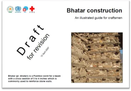
In order to give a reference point, international organizations such as ERRA , UN-HABITAT, SDC and FRC have published “Bhatar construction - An illustrated guide for craftsmen”.
Guidebook prepared by the Swiss Agency for Development and Cooperation SDC (Tom Schacher, technical advisor).In collaboration with: French Red Cross and Belgian Red Cross (technical research and development) UN Habitat, NSET and NESPAK (revisions) French Red Cross (Translation into Urdu) Mansehra, NWFP, April 2007
This guide shows how to built-up a bhatar house and the gross dimensions that must be satisfied.
Thus, this research was performed to ensure that this alternative building technique can be built in a seismic region knowing that it will be a safe structure and that can be used for a post-disaster reconstruction in developing countries.
1.2 Justification of the document and objectives
The use of bhatar system is a traditional technique in the construction field and it is widely used all over the Himalayan area due to some factors such as durability of the structure, low environmental impact, cost-effective ratio.
Considering the advantages that this system carries, it can be an alternative building technique and post-disaster reconstruction for houses in developing countries where it can be used for individual housing or for community facilities. Thereby, this technique can be built in remote areas, locations
2
difficult to reach and poorly supplied areas with the advantage that gabion boxes are easily installed and that deployment can be performed without special equipment and there is no need of highly trained personnel.
On the other hand, from a seismic point of view, there will be “weight issues” because the bhatar are heavy due to the rocks (it’s known that the seismic forces acting on the structure are proportional to the weight). Thus, the need of research has been identified in order to understand the static and seismic behavior of this kind of structures focusing on the limitations of the system and the structural safety under a certain seismic action.
1.2.1 General objectives
Based on the justification of this document, this dissertation aims at understand the behavior in-plane and out-of-in-plane under seismic actions of a modular box composed by walls built-up with bhatar method and to give practical suggestions and simple formulas for the dimensioning of the structure, satisfying structural safety conditions.
1.2.2 Specific objectives
To comprehend the compression behavior and strength of a single Wall,composed by elementar modules under vertical loads.
To verify the structural safety under seismic actions in-plane and out-of-plane of a wall build-up with bhatar system.
Conduct analytical considerations to examine the effect of lateral forces on the behavior of a bhatar system.
Propose constructions details and limitations to acquire an assure good seismic behavior of the structure
To develop rules of thumb for a proper dimensioning and construction of this kind of structures in order to be a seismic resistant structure.
1.3 Organization of the thesis
The work has been organized starting from the elementary elements used in the Bhatar system thus starting from the geometry following the guide line of Architect Tom Schacher.
The following points shows the steps of the logic path followed in the work: Studies of Tom Sacher manual
3
Definition of the wall
Definition of one room module (box)
Definition of material properties: Timber SHOREA ROBUSTA Definition of material properties: Stones LIMESTONE
Studies on Rock discontinuities: Barton model –
Connections - Eurocode 5 : EN 1995-1-1 :2004+A 1- DESIGN ULS Static Analysis
Seismic analysis in plane – application of Barton model Seismic analysis out of plane – Overturning
Seismic analysis out of plane – Bending Practical rules of thumb.
2
2 BHATAR
2.1 Traditional definition of Bhatar
Bhatar is a traditional construction system consisting of stone mortarless masonry walls reinforced
with horizontal timber ladder-beams, which combine to resist and dissipate the energy and stresses induced during an earthquake.
Figure 2-1 Project entry 2008 Asia Pacific - "Advocacy of traditional earthquake-resistant construction, North-West Frontier Province, Pakistan": “Bhatar” at Besham Fort.
Through the century and countries this kind of architecture has been used for many different purpose and different scale, temples for religions forts for military camp and houses for civil use.
Along the time some of these structures of the past are still standing after important earthquake, this suggest us that bhatar system has somehow a good seismic behavior. The different between the constructions that have survived and those who did not may be due to many factors. The knowledge of the know-how goes from an old generation to a new one, because of this there are many
differences about materials, about the proper place where to build but most of all the differences about the techniques are the most important.
In the poor and lost areas where this kind of architecture is used is important to use local material and to avoid the use of material or component which need to be imported from somewhere else, this is not just because it is important to save money but most of all because there are no proper
3
This type of construction has been extensively used in Turkey,Afghanistan, Pakistan, India and Nepal for many centuries, as shown in figure below.Nepal is the country taken as reference point for the local material.
Figure 2-2 Regions of the world where Bhatar is still used
Nepal is subjected to very strong earthquake because its characteristic positionas shown in the picture2-3.
4
2.2 Tom Schacher Manual : Bhatar construction - An illustrated
guide for craftsmen
Arch Tom Schacher
Figure 2-4 Bhatar construction-An illustrated guide for craftsmen
2.2.1 Gross shape and dimensions
The fisrt thing described is the position of the structure and the gross shape.As it is shown in the figure 2-5 it is always better to choose a simple and regular structure , if necessary it is better to subdivide it into rectangular parts.
Figure 2-5 Divided rectangular structures
The first suggestion about the dimensions is the relation about the length and the width.The house must not be longer than three times the width , as it is shown in figure 2-6.
5
Figure 2-6 Gross dimension - ratio length/width
2.2.2 Foundation and plinth band
The foundation should be at least 2½ feet(0,762 m) wide and 3 feet (0,91 m) deep. The plinth band should be placed 1 foot ( 0,3 m) above the foundation (1 foot out of the ground) in order to avoid the contact with water, as it is shown in figure 2-7.
Figure 2-7 Foundations
The plinth band must pass under the door. It should be continous along all the perimeter (better if it is made in RC , it will not rot ), , as it is shown in figure 2-8.
Figure 2-8 The plint
2.2.3 The Walls
6
Figure 2-9 Wall dimensions
The drawing is not in scale, in a real scale it would be appreciated the fact that the spaces are quite small then the necessity to add the rooms.
2.2.4 Wall - joints
The timber elements may be not enough long to cover all the length of the wall so it is suggested to use scarf keyed joint along their length but taking into account that at each level they must be in different position and not along a vertical line as shown in figure 2-10., at the same time the
position of the stones must be always laid down in order to have a dovetail as shown in figure 2-11
7
Figure 2-11 Raise all walls together to avoid vertical joints
2.2.5 Kashmiri joint or Keyed scarf joint
The joints in the timber element must be done with Kashmiri joint or normally known as keyed scarf joint as shown in figure2-12.
Figure 2-12 Kashmiri joint or Keyed Scarf Joint
2.2.6 Connections - Corners
The connections on the corners stand due to lap joints and Minimum size of beam is 3” (7,62 cm) high by 4” ( 10,16 cm )wide, as shown in figure 2-13.
8
Beams must be hooked together in the corners. Cut a notch of 1” (2,54 cm) into all four corner beams. Add 2 nails (3” =7,62 cm ) for more security.Keep 4” ( 10,16 cm ) of wood after all notches for strength.As shown in figure2-14.
Figure 2-14 Lap joint – dimension
2.2.7 Connections – Cross Pieces
Along the wall cross pieces must be insert in order to assure stability. Cross pieces help to hold the beams and walls together.You need notches only on the cross pieces, but not on the main beams. As shown in figure2-15
Figure 2-15 Cross Pieces
2.2.8 Connections – Internal wall
In case of double room they are specified how the connections between the walls must be done. Minimum size of beam is 3” (7,62 cm) high by 4” ( 10,16 cm )wide. Where internal walls connect, only notch the internal wall beams, not the main beams, as shown in figure2-16.
9
Figure 2-16 Internal wall joint
2.2.9 Openings
The distance between openings should be minimum 3 feet (0,91 m) ,windows and doors must not be wider than 3 feet (0,91 m) ,the windows must be between the beams. As shown in the figure2-17
Figure 2-17 Openings
2.2.10 Doors
The integrity of the structure must be assured thus it must be avoided any modification and all the openings must be bounded with cross pieces as shown in figure 2-18
10
2.2.11 Windows
The windows must be reinforced with beams, for lintel must be added two pieces of wood in
between the existing beams to support stones above. It must pass at least 1 foot(0,3 m) into masonry on each side of the opening, as shown in figure 2-19
Figure 2-19 Lintel reinforcement
2.2.12 The Roof
The roof considered for this research is the flat heavy roof with earth cover which is the worst case but it does not need metal sheet to cover which are difficult te be found in far regions.
Some suggestions are given referring the figure below. 1-Let the top beams (bhateri) stick out of the wall 1 foot on each side. Connect them with nailed cross pieces. 2-Add the 4”x6”roof beams and let them too stick out 1 ft on each side (also over the retaining back-wall if there is) to protect the wall against rain. 3- Nail the planks on the roof beams leaving a half inch gap between each. 4-Place flat stones along the edge of the roof to contain the earth. 5- Add twigs and small branches in a layer 4 to 6 inch thick. 6 Cover with earth 4 to 6 inch thick. 7-Avoid to make the earth cover thicker over the years.
11
3 STUDY CASE
Following the Tom Schacher Manual
Following the guide lines given by Architect Tom Schacher it has been defined a basic module of the wall which can be used as modular unit in order to built square or rectangular housing unit.
3.1 Single modular unit
In accordance to the manual the single unit has been drawn starting from the ground layer until the roof support.The beams are placed every 60 cm exept the first beam from the bottom and the roof beam that are placed at 30 cm. The global measure are shown in the figure 3-1.
12
3.1.1 Orthogonal projection
13
3.2 Single Wall
Using the modular unit it has been composed the largest wall suggested by the guide line. With a length of 12 feet it has been approximated to 3.6 m, width of 0,46 m and height of 3.1 m.
Figure 3-3Largest wall possible , length of 3.6m
3.2.1 Orthogonal projection
14
3.3 One room box
Using four perimetric wall for a total around 12 modular units a room box have been defined. This room box is the largest single habitat unit which can be built with the use of the guide line.The one room box is composed by:
• Foundation and plinth band made of stones • First seismic band made of wood
• Dimensions (length : 3,60 m ;Width : 3,60 m; Height 3,0 m) • 1 door
• 2 window
15
3.3.1 Orthogonal projection
Figure 3-6 One room box orthogonal projections in cm
In the guide line is described the possibility of enlarging the structure adding walls in order to compose a second smaller habitat unit .The aim of the thesis is to understand the behavior of the basic structure thus all the studies regards the basic room box and in particular the behavior of the perimetric wall. As shown in the following figure the section AA represents the studied wall.
16
Figure 3-7 Section AA - studied wall
3.3.2 The Roof
The roof has been considered as flat heavy roof with earth cover which is composed , as show in the figure below, by (from the bottom):
Last timber band
Roof beams 10 cm height Planks 3 cm height
Ring of flat stones 10 cm height Twigs 5 cm height
17
18
4 MATERIALS
This chapter describe the two basic material, timber and stones used in the Nepal region.
4.1 Timber : Shorea Robusta
Thanks to the suggestions of Architect Martijn Schildkamp we know that exact timber traditionally used in Nepal to build Bhatar structures is the so called Shorea Robusta in Nepal language is called SAL.
4.1.1 Botanic Characteristics
Below in the figure are reported the botanic characteristics.
Figure 4-1 Shorea Robusta – SAL
4.1.2 Mechanical properties of Shorea Robusta
In order to find the proper mechanical properties of Shorea Robusta it has been necessary a bibliographic research. This reaserch ended with 4 important sources which are listed below:
Source 1 : MECHANICAL PROPERTIES AND DURABILITY OF SOME SELECTED
TIMBER SPECIES ( M. Bellal Hossain1 and A.S.M. Abdul Awal2*)
Source 2 : STUDIES ON TENSILE STRENGTH PROPERTY OF COMMERCIAL TIMBER SPECIES OF SOLAN DISTRICT ( Himachal Pradesh SEEMA BHATT, BUPENDER DUTT, RAJESH KUMAR MEENA and TASRUF AHMAD*)
Source 3 : COMPARISON OF TEST RESULTS OF VARIOUS AVAILABLE NEPALESE
TIMBERS FOR SMALL WIND TURBINE APPLICATIONS (R. Sharma1 1 1 , R.
Sinha , P. Acharya , L. Mishnaevsky Jr. 2, P. Freere3)
19
The different values found in the research have been averaged and they are reported in the following table.
Table 1 Shorea Robusta mechanical properties 1
Sal or Shorea robusta
Density ρ : ( Kg/m3)
Specific gravity SG = ρsubstance / ρH2O
ultimate compressive strength σu (Mpa)
Tensile Ultimate stress longitudinal axis (MPa)
source 1 921 0,84 48 /
source 2 / / / 78,1
source 3 913 or 950 / / /
source 4 875 / 61 /
Average 914,75 0,84 54,5 78,1
Table 2 Shorea Robusta mechanical properties 2
Sal or Shorea robusta
Young's Modulus E : (Gpa) Bending Strength ( Mpa) Minimum Static Bending Strength (Mpa)
Average Hardness (Mpa) Indentations : Incavatura Minimum Hardness (Mpa) source 1 / / / / / source 2 / / / / / source 3 12,55 83,85 61,7 87,5 (+o- 42,5) 45 source 4 15,6 121 / medium/high / Average 14,075 102,425 61,7 87,5 (+o- 42,5) 45
4.1.3 Characteristic Values from EN 338
Comparison with Classification of timber in accordance with UNI EN 338 : 2009 Shorea Robusta is classified as D70 thus they have been used the following reference values.
Shorea Robusta Hardwood species D70
Strength properties (in N/mm2)
Bending ƒm,k 70 Tension parallel ƒt,0,k 42 Tension perpendicular ƒt,90,k 0,6 Compression parallel ƒc,0,k 34 Compression perpendicular ƒc,90,k 13,5 Shear ƒv,k 5,0
Stiffness properties (in kN/mm2)
Mean modulus of elasticity parallel E0,mean 20 5 % modulus of elasticity parallel E0,05 16,8 Mean modulus of elasticity perpendicular E90,mean 1,33 Mean shear modulus Gmean 1,25
Density (in kg/m3)
Density ρk 900
20
4.1.4 Design Values from EC 5 and en.1995.1.1.2004 and NICOLE –
Istruzioni CNR_DT206_2007
Following the Eurocode 5 and the national codes for the design timber structure they have been selected and computed the following values.
Table 3 Design Value EC5-Nicole -1
DESIGN VALUE
the partial factor for a material property γm 1,5
Service class 2
modification factor taking into account the effect of the duration of load and moisture
Kmod permanent action
1,1
Depth factor kh From case
Table 4 Design Value EC5-Nicole -2
Strength properties (in N/mm2)
Bending ƒm,d 51,33 Tension parallel ƒt,0,d 30,80 Tension perpendicular ƒt,90,d 0,44 Compression parallel ƒc,0,d 24,93 Compression perpendicular ƒc,90,d 9,90 Shear ƒv,d 3,67
Stiffness properties (in kN/mm2)
Mean modulus of elasticity parallel E0,d 13,33 5 % modulus of elasticity parallel E0,05 d 11,20 Mean modulus of elasticity perpendicular E90,d 0,89 Mean shear modulus Gd 0,83 Density (in kg/m3)
Density ρk 900
Mean density ρmean 1080
4.2 Stones : Main construction material since the Stone Age
In order to define the most probable stone largely used for the construction of bhatar the research has been started looking on which are the most common stones in the Nepal region taken as reference point. Thanks to Architect Martijn Schildkamp we know that people collect the stone from the ground and sometimes they take them directly to the quarries.
The most common rocks and their used in the Nepal region are listed below :
marble, basalt, granite and red sandstones are cut into slabs and used in decoration; phyllite, slates, flaggy quartzite and schist are used for roofing;
limestone, dolomite, quartzite, sandstone are used for aggregate in various construction works, road paving and flooring;
21
vast quantities of river boulders, cobbles, pebbles and sands are mined as construction materials/ aggregates.
References :
DMG (Y.P. Sharma et al 1988) has evaluated such materials (boulders=347,006,000m3, cobbles=214,261,000m3 and pebbles=229,205,000m3) in the major rivers of Terai region.
MINERAL RESOURCES OF NEPAL AND THEIR PRESENT STATUS- Krishna P. Kaphle, Former Superintending Geologist, Department of Mines and Geology, Kathmandu, Nepal Former President, Nepal Geological Society
The world Housing Encyclopedia (WHE) specify that the rocks most used in wall and frame as rubble stones are Slates ,Limestone, Quartzite.
Architect Martijn Schildkamp collected pictures during the construction of a bhatar house.
Comparing the pictures of the stones he sent and weaving togheter the possible material, it has been choosen the strongest one, limestone.
Figure 4-2 Architect Martijn Schildkamp - bhatar stones