Chapter 1 – The High Temperature He-cooled pebble-bed
Plant
1.1 Power plant description
In this chapter we are going to see the description on the PBMR-400[1-5] designed by Pebble Bed Modular Reactor (PBMR) Limited (South Africa). The evolution of the PBMR shows some interesting things. For example the design described in [I-3] and [I-4] is rather different from the present version. Particularly we will focus on the vessel and core, the plant components fundamental for the neutronic studies carried on in this thesis. The description of some further plant components is reported in Appendix A.
In the mid-90’s the Pebble Bed Modular Reactor (PBMR) came to the fore-front as a possible option for the installation of new generating capacity by ESKOM, the electric utility of South Africa. The PBMR is a pebble-bed High Temperature Gas Cooled Reactor (HTGR). The PBMR incorporates a closed cycle primary coolant system with helium as coolant, flowing directly from the pebble-bed core to a recuperative conversion unit, consisting (in the last version of the design[1-5]) of a single-shaft turbine/compressor/generator system. Using a direct Brayton instead of the Rankine cycle (used in almost all the present nuclear power plants), PBMR allows to achieve the following benefits:
• to simplify the system,
• to increase substantially its overall efficiency and its inherent safety • to reduce capital and operational costs.
The following table (Table 1.1) shows the principal characteristics of the PBMR-400 reactor. The operational transient, using as reference the power cycle (100÷40÷100%) for load following capability, is described in [1-2].
Table 1.1: Major Design and Operating Characteristics of PBMR[1-2] PBMR Characteristic Value
Installed thermal capacity 400 MW(t) Installed electric capacity 165 MW(e) Load following capability 100÷40÷100% Availability ≥ 95%
Core configuration Vertical with fixed centre graphite reflector
Fuel TRISO ceramic coated U235 in
graphite spheres Primary coolant Helium
Primary coolant pressure 9 MPa
Moderator Graphite Core outlet temperature 900°C
Core inlet temperature 500°C Cycle type Direct Number of circuits 1
Cycle efficiency ≥ 41% Emergency planning zone
(radius)
400 meters
As mentioned above, the PBMR realizes a direct Brayton cycle with the primary coolant (He) flowing downward through the core and exiting at 900°C. The operational pressure in primary coolant is 9 MPa. Then, Helium enters into the turbine using its energy to drive the electric generator and compressors. Actually, the turbine is mechanically connected to the generator through a speed-reduction gearbox on one side and to the gas compressors on the other side. After leaving the turbine at a temperature of 500°C and to a pressure of 2.6 MPa, Helium passes consecutively through the LP primary side of the recuperator, then goes to the pre-cooler, the low pressure compressor, the intercooler, the high pressure compressor and finally to the HP secondary side of the recuperator, before re-entering the reactor vessel at 500°C. Figure 1.1 provides a schematic view of the PBMR plant, particularly of its power conversion system (PCU) layout.
Figure 1.1: Conceptual Layout of the PBMR Primary System[1-5]
The thermodynamic cycle used is a Brayton cycle with a water-cooled pre-cooler and interpre-cooler. A high efficiency recuperator is used after the power turbine. The helium cooled in the recuperator, is passed through the pre-cooler, low pressure compressor, the intercooler and high-pressure compressor before being returned through the recuperator to the reactor core (see Figure 1.2). The power taken up by the helium in the core and the power given off in the turbine is proportional to the coolant mass flow for the same temperatures in the system. The mass flow rate depends on the pressure, so the power can be adjusted by changing the pressure in the system. This is achieved by a combination of compressor bypass and system pressure changes. Increasing the pressure results in an increase of the mass flow rate, which results in an increase of the power extracted from the core. The larger flow of Helium in the core has also the consequence of increasing the heat transfer coefficient. The power reduction is achieved by removing gas from the circuit. A Helium Inventory Control System is used to provide the increase or decrease in system pressure.
The high pressure and high temperature operations of the reactor lead to a relatively high thermal efficiency. While a typical light water reactor has a thermal efficiency (electrical power output/thermal heat input) of
approximately 35%, an efficiency of about 45% is anticipated in the basic PBMR design.
Online refuelling is another key feature of the PBMR. Fresh fuel elements are added to the top of the reactor while used fuel is removed at the bottom while the reactor is at power. The aim is to operate uninterrupted for six years before the reactor is shut down for scheduled maintenance. For the demonstration module, however, a number of interim shutdowns will be required for planned evaluation of component and system performance. Shutdown will be done by inserting the control rods. Start-up is effected by making the reactor critical, then using nuclear heat-up of the core and circulating the coolant by motoring the turbo-generator set. In this phase, heat is removed by the pre-cooler and intercooler. At a specified temperature, the cycle becomes self sustaining.
1.2 The PBMR-400 vessel and internals
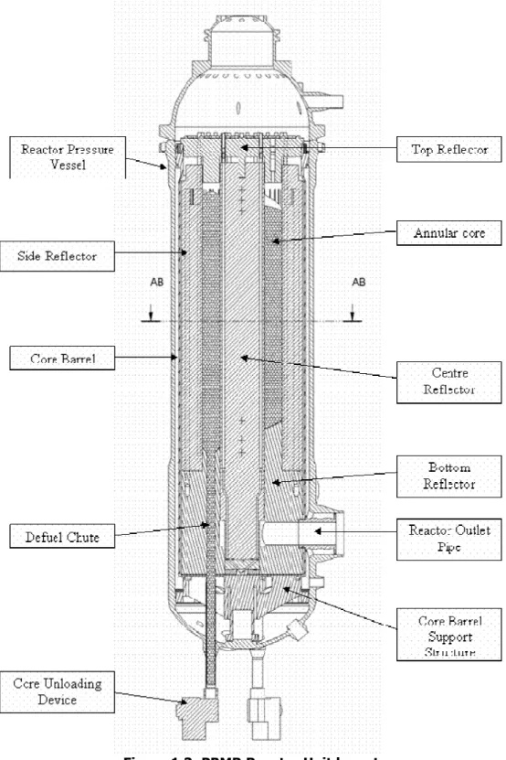
The PBMR has a 27 m high vertical steel Reactor Pressure Vessel (RPV) with an inner diameter of about 6.2 m. The RPV contains and supports a metallic core barrel. The core barrel, in turn, supports the annular pebble fuel core, which is located in the space between a central and the outer graphite reflectors. Vertical borings in these reflectors are provided for the reactivity control elements. The PBMR pressure vessel and its core layout are shown in Figure 1..
The most important characteristics of the PBMR core are the following:
• An annular core with an outer diameter of 3.7 m and a ‘fixed central reflector’, made of graphite, with an outer diameter of 2 m
• An effective cylindrical core height of 11 m • A graphite side reflector of ~90 cm thickness
• The Reactivity Control System (RCS), consisting of 24 partial length control rod in the side reflector: the upper half are the 12 control rods, which constitute the 12 shutdown rods with the 12 lower halves, when they are fully inserted all together. During the normal operational conditions all the 24 rods operate together. The effective length of the control rods is 6.5 m, and their neutron absorbing material is B4C
• The Reserve Shutdown System (RSS), consisting of 8 Small Absorber Sphere (SAS) systems positioned in the fixed central reflector and filled with 1 cm diameter absorber spheres containing B4C
• 3 fuel loading positions and 3 fuel unloading tubes, positioned equidistantly to the centre of the fuel annulus
In the present design[1-1] [1-2] the core contains ~ 452000 fuel spheres or “pebbles” with a mean packing (volume) fraction of 0.61(random packing). The two different reactivity control systems[1-2] are used for shutdown purposes and minor reactivity adjustments. The driving systems are similar, each of them has a stepper motor with a gearbox driving a chain wheel that locates the chain on which the control rod is supported. When inserted at their maximum depth into the side reflector, the upper set of control rods move to a 6.5m depth below the bottom of the top reflector and the shutdown rods move to the lower part of the core, at a 10m depth. This results in an overlap of all rods around the centre of the core. The RCS rods move in borings in the side reflector. The second system, the Reserve Shutdown System (RSS), consists of 10 mm diameter B4C absorber spheres,
shutdown. The spheres are normally stored in containers at the top of the core structures, and they are released by opening a valve system.
More details of core are shown in Table1.1 and Table 1.2, while a picture is shown in Figure1.3 and Figure 1.4.
Table 1.1: Core Geometrical Specifications at Room Temperature[1-2]
Description Unit Value
Equivalent core outer radius m 1.85 Cylindrical height of the core (Flattened
core surface at the top and flat bottom reflector).
m 11.0
Total core volume m3 83.72
Fixed central column graphite reflector radius
m 1.0 Effective height of the upper void cavity
(levelled core surface to bottom of top reflector).
m 0.5
Effective annular thickness of the side reflector (graphite).
m 0.9 Inner radius of the core barrel m 2.88
Wall thickness of the core barrel. m 0.05 Inner radius of the RPV m 3.1 Wall thickness of the RPV. m 0.18 Radius of cooling system / 20˚ C
temperature isothermal boundary
m 4.62 Radii of five material meshes in core (5
radial material meshes in core, equal width) m 1.17 1.34 1.51 1.68 1.85 Thickness of core radial meshes (all
equal)
m 0.17 Axial material mesh: 11.0 m / 22 meshes
(in core)
m 0.5 Outlet plenum inner diameter m 1.0
Outlet plenum outer diameter m 1.85 Outlet plenum height m 0.5 Inlet plenum inner diameter m 2.436
Description Unit Value
Inlet plenum outer diameter m 2.606 Inlet plenum height m 0.5 He riser channel skirt / porous region
inner radius
m 2.436 He riser channel skirt /porous region
outer radius
m 2.606 Distance from bottom of core to top of
the inlet plenum
m 1.5 Centre line axial distance between inlet
and outlet plenum
m 1.0 Top inlet plenum inner diameter m 1.85
Top inlet plenum outer diameter m 2.606 Top inlet plenum height m 0.5 Distance from bottom of top reflector to
bottom of top inlet plenum (in the side reflector)
m 1.0
Total height of top reflector m 1.5 Total height of bottom reflector
(Distance from top of bottom plate to bottom of core).
m 4.0
Top steel plate thickness m 0.35 Bottom steel plate thickness m 0.35
Table 1.2: Number-densities for Non-fuel regions[1-2] Isotope Graphite (reflector) all regions RCS/RSS Core Barrel C 8.925E-02 8.925E-02 0.0 B-10 1.0E-09 6.0E-06 0.0 Fe (Nat) 0.0 0.0 5.810E-02 Cu (Nat) 0.0 0.0 3.861E-04 Co-59 0.0 0.0 1.544E-04 Si 0.0 0.0 2.488E-04 Ni (Nat) 0.0 0.0 7.996E-03 Mo (Nat) 0.0 0.0 1.733E-03 Mn – 55 0.0 0.0 1.278E-03 Cr (Nat) 0.0 0.0 1.590E-02
Figure 1.5: Reactor pressure vessel[1-5]
1.3 Recirculation system
The refuelling scheme envisaged for the PBMR is the continuous on-line multi-pass scheme, which is similar to that used in the past for the German AVR[1-4]. On average, each fuel pebble passes six times through the core before being finally discharged to the spent fuel storage tanks with a >90000 MWd/tU target burn-up.
The core of pebble bed reactors, like PBMR-400[1-5], is constituted by a cavity filled with pebbles of 3 cm diameter. As already sayed, typically a
PBMR contains ~452000 fuel spheres or “pebbles” with a packing fraction of 0.61. Fresh fuel elements are added to the top of the reactor while irradiated fuel pebbles are removed from the bottom to keep the reactor in a critical condition. In a day Reactor Recirculation System (RRS) loads ~1500 pebbles[1-6] (rate of recirculation).
The pebbles which reached the bottom of the core are extracted and checked. A first system verifies their integrity. If a pebble is damaged, the system puts it in the exhaust container. The second check is performed by a criticality control system. It consists of a subcritical system that is able to measure the burn-up of a pebble. If the burn-up of a pebble has not reached a preset limit, the considered pebble can be loaded into the core again. If that does not happen, the fuel element is exhausted and it has to be placed in the Exhaust Camera.
The fuel spheres are loaded or re-loaded into the core through three fuelling lines. The fuel handling system consists of a core-unloading device placed in each of the three de-fuelling chutes from which pebbles are moved pneumatically to the burn-up assaying equipment. After the burn-up has been determined, the fuel is routed either to the spent fuel tanks or back to the core, depending on its burn-up. For each pebble eliminated, the Circulation System introduce a new fresh pebble. At the moment of loading in the core, the pebbles are inserted at 6 m/s. This value represents the highest velocity at which a pebble can run without being damaged by collisions with other pebbles[1-6].
1.4 Conclusive considerations
Among the innovative Western nuclear reactors, the High Temperature Gas Reactor (HTR) represents one of the most interesting candidates, both in terms of safety (very high) and of relativity of the costs and low environmental impact, even regarding thermal pollution.
The safety features of PBMR (and more generally of HTR) are well-known. These characteristics are the main reasons of the interest for the development of the HTR (or HTGR, High Temperature Gas Cooled Reactor, as these reactors are known outside the EU).
The great number of proposed HTR designs has often hidden the evolution phases of this type of reactors. However, today, these reactors can be considered an innovative answer to the world energy demand, both for the electric energy and for the hydrogen production, as well as for the desalinization systems. The results[I-2] that could be obtained from operation of HTTR in Japan and HTR-10 in China, in conjunction with the experience already available from other GCRs[I-2], constitute a strong technological basis for present and future commercial development of HTRs (e. g. PBMR).
Looking at the PBMR, some interesting considerations can be underlined: 1. The adoption of direct cycle in conjunction with the high temperature
allow to obtain high plant efficiency (~45% vs. ~35% typical of LWRs) 2. Coolant high temperature (even more than 900°C) leads to the use in
the frame of high temperature chemical activities (e.g. steam reforming or sulphur-iodine hydrogen production [1-7][1-8]).
3. Improved neutronic economy and material choices permit the possibility of implementing innovative fuel cycles in order to reduce the long term radiotoxicity of spent fuel[1-9].
4. The safety and reliability are two important improvements in this type of reactor[1-6].
5. The pebbles can resist at high temperature (up to 1600°C and higher) without a significant release fraction of fission products even in case of accidents[I-3].
6. HTRs could remove the decay heat only by conduction without active systems (the reactor remains in a safe condition only with heat conduction to the soil).
As already said, further data on this reactor are reported in Appendix A.
The potentialities of the HTRs[I-2] are surely one of the more fascinating and stimulant prospects in the framework of a really sustainable environmental and social development of our society.
![Table 1.1: Major Design and Operating Characteristics of PBMR[1-2] PBMR Characteristic Value](https://thumb-eu.123doks.com/thumbv2/123dokorg/7322949.89817/2.892.116.774.131.792/table-major-design-operating-characteristics-pbmr-characteristic-value.webp)
![Figure 1.1: Conceptual Layout of the PBMR Primary System[1-5]](https://thumb-eu.123doks.com/thumbv2/123dokorg/7322949.89817/3.892.84.806.100.617/figure-conceptual-layout-pbmr-primary.webp)
![Figure 1.2: PBMR – Main Power System Diagram[1-5]](https://thumb-eu.123doks.com/thumbv2/123dokorg/7322949.89817/4.892.88.829.466.960/figure-pbmr-main-power-system-diagram.webp)
![Table 1.1: Core Geometrical Specifications at Room Temperature[1-2]](https://thumb-eu.123doks.com/thumbv2/123dokorg/7322949.89817/7.892.142.757.96.1189/table-core-geometrical-specifications-room-temperature.webp)
![Table 1.2: Number-densities for Non-fuel regions[1-2] Isotope Graphite (reflector) all regions RCS/RSS Core Barrel C 8.925E-02 8.925E-02 0.0 B-10 1.0E-09 6.0E-06 0.0 Fe (Nat) 0.0 0.0 5.810E-02 Cu (Nat) 0.0 0.0 3.861E-04 Co-59 0.0 0.](https://thumb-eu.123doks.com/thumbv2/123dokorg/7322949.89817/9.892.200.691.115.602/number-densities-regions-isotope-graphite-reflector-regions-barrel.webp)
![Figure 1.5: Reactor pressure vessel[1-5]](https://thumb-eu.123doks.com/thumbv2/123dokorg/7322949.89817/10.892.205.692.129.800/figure-reactor-pressure-vessel.webp)
