POLITECNICO DI MILANO
I School of Engineering
Master of Science Course in Civil Engineering Department of Civil and Environmental Engineering
A BRIDGE MADE OF COMPOSITE
PLASTIC TUBES AND CONCRETE FOR
A BASIC ROAD NETWORKS
Supervisor:
Prof. Ing. Pier Giorgio MALERBA Co-Supervisor:
Ing. Elisa CONTI
Master Thesis by:
Thomas FOURDINIER 836798
Concrete for a Basic Road Networks. © December 2016
Politecnico di Milano Department of Civil and Environmental Engineering Graduation session: 21 December 2016
Preface
My special thank and acknowledgement go to Ing. Nicolas Metge, who gave me the opportunity to intern at the Company ISC. This experience was extremely dense and rich, as I was confronted to many different projects and types of infrastructure. I could also work at a great variety of levels: public tenders, technical expertises, execution studies. This stage answered my personal desires of understanding and entering deeply into subjects. He did not hesitate to give me autonomy and respon-sibility, and I really appreciated being challenged as I was at ISC. My appreciation also goes to the entire ISC team, always available for explanations, prompt to share their knowledge and willing to learn more.
Special mentions go to Ing. Patrick Barbier and Ing. Riyadh Benosman, who particularly supported me during these six months and communicated their passion, enthusiasm and know-how.
I would like to express sincere gratitude to Prof. Ing. Pier Giorgio Malerba for the time and attention he dedicated to my thesis project. He was sufficiently patient and open-minded to examine the work I suggested. I thank him for sharing his large know-how and experience in civil works and especially his expertise in bridges.
Finally, a large thank you goes to Ing. Elisa Conti for her help preparing and setting this work. Its advice has showed very precious for me to understand and answer the expectations of a thesis work in Italia. Her availability and enthusiasm was a constant support during the last months.
Milano, December 2016 Thomas Fourdinier
Abstract
The present thesis work takes advantage of the opportunity of a stage, at ISC, a French engineering firm. This company, whose field includes Africa, develops new structural design processes, to adapt to the local context. Hence, the present work aims at developing such a process for a footbridge. Starting from a blank page, requirements include durability of the material, low environmental and economic impact of the structure, simplicity of the process. To fulfil them, the structure shall be light, requiring manhandling elements and no lifting machine. These specifica-tions open two main inter-dependant fields of prospects: the static scheme and the material.
The thesis follows the path opened by a first design attempt made by ISC: a reinforced concrete bridge, cast in PVC tubes. Taking account achievements and limitations of the experience, this thesis develops and expands this intuition, enlarg-ing the use of PVC. First, a different static scheme, that fits better the particularities of PVC, is chosen. The nature of a piping system offers its modularity and container ability, whose interest is weighted in the project framework.
Then, despite the proven interest of PVC for piping systems, the main obstacle to use it in civil engineering is the lack of knowledge the sector has about the mechanical abilities of PVC. Therefore, it is necessary to investigate its types, its modes of production, its characteristics, its reference codes and its structural behaviour of this plastic. Its principal semi-finished derivatives, tubes and fittings, are analysed in terms of geometry and possible implementation.
Once the useful equipment has been presented, several attempts are made before designing the footbridge. Among them, a scale model is realized, to experience and improve the static scheme. Loading test is led and analysed. It helps assessing the structural abilities of PVC piping systems.
To find a correct shape, the study has reaped huge benefits from the use of a parametric algorithm, Grasshopper, combined to a 3D software, Rhinoceros. After parameters are determined, a complete algorithm has been written to model the geometry of the footbridge, and convert it into finite elements thanks to the use of Karamba.
supported by a metallic cable, is built. Reinforcement is disposed before is filled with concrete. The model is calculated under different load cases. Peculiarities of realization are pursued to the very detail of execution studies and normative verifications to European standards.
Originality resides in the structural role given to PVC tubes during concreting phase. This thesis concludes as a matter of fact with the delivery of a ready-to-built footbridge.
Sommario
Il presente lavoro di tesi si avvale della possibilità di uno stage, svoltosi presso lo studio di ingegneria francese ISC. La società, inserita nel contesto di sviluppo dei paesi del continente africano, rivolge la sua attenzione a progetti nuove strutture che si adattino al contesto locale di riferimento. Il presente lavoro, inserendosi in tale contesto, si propone dunque di studiare una passerella pedonale.
Una prima fase è rivolta allo studio dei requisiti quali la durabilità del materiale, il basso impatto ambientale ed economico della struttura, la semplicità del processo di costruzione. Al fine di soddisfare questi criteri, la struttura scelta dovrà essere leggera e composta da soli elementi sufficientemente leggeri per essere trasportati a mano, in modo tale da non richiedere opportune macchine di sollevamento. Tali specifiche aprono lo studio a due principali campi interconnessi tra loro: lo schema statico e il materiale.
La Tesi prende spunto inizialmente da un tentativo di nuovo design progettato da ISC: un ponte in cemento armato, gettato mediante tubi in PVC. Considerando in conto i risultati e le limitazioni di questa nuova idea, il lavoro si sviluppa e espande, ampliando l’utilizzo del PVC come materiale strutturale. In primo luogo viene scelto uno schema statico differente, che si adatti meglio alle peculiarità del PVC. In particolare, la natura del sistema di tubazioni manifesta ottime capacità in termini sia di modularità e sia di involucro, il cui relativo interesse è messo in luce nel contesto del progetto.
Nonostante l’interesse del PVC per i sistemi di tubazioni, la principale difficoltà che si manifesta nel campo dell’ingegneria civile riguarda la mancanza di conoscenza che il settore ha nei confronti delle sue capacità meccaniche. Pertanto, è stato neces-sario analizzare le diverse tipologie di PVC attualmente in uso, i modi di produzione, le caratteristiche fisiche e meccaniche, così come le normative di riferimento e il suo comportamento strutturale. I principali semilavorati di derivazione, come tubi e raccordi, vengono analizzati dal punto di vista della geometria e della possibilità di attuazione.
Presentato il materiale e i suoi prodotti a disposizione, diversi tentativi relativi allo schema statico sono fatti prima di progettare la passerella. Tra questi occorre citare il modello in scala realizzato ad hoc per sperimentare e migliorare lo schema
statico. Eseguendo una prova di carico è stato inoltre possibile valutare le capacità strutturali dei sistemi di tubazioni in PVC.
Per definire una forma geometrica appropriata, in questo lavoro si è ricorso all’utilizzo di un software Grasshopper basato su un algoritmo parametrico. Una volta determinati i parametri, all’interno del software utilizzato è stato possibile scrivere un algoritmo per modellare la geometria della passerella e successivamente convertirlo in elementi finiti. Infine l’analisi strutturale è stata eseguita mediante l’utilizzo del programma Karamba.
Dopo la validazione del modello, si sono studiate e verificate le diverse fasi del progetto della passerella. Si definisce uno scheletro integrale in PVC, sostenuto da un cavo metallico. Prima del getto viene disposto il rinforzo e riempito con calcestruzzo. Il modello viene analizzato sotto diverse condizioni di carico. Vengono infine definiti i dettagli costruttivi e vengono eseguite le verifiche in accordo agli standard europei. L’originalità del lavoro risiede nel ruolo strutturale dato a tubi in PVC durante la fase di getto e nella definizione di u progetto di una passerella finalizzata alla sua reale applicazione in paesi in via di sviluppo.
Contents
Preface iii
Abstract v
Index xiii
List of Figures xviii
List of Tabels xx
1 Introduction 1
1.1 Background . . . 1
1.2 Aim . . . 1
1.3 Approach . . . 2
1.4 Limitations and assumptions . . . 2
1.5 Used Software . . . 3
1.6 Thesis framework . . . 3
2 A Different Way to Realize Structures 5 2.1 Modularity concept . . . 5
2.2 Examples of modular structures . . . 8
2.2.1 Paper Bridge . . . 8
2.2.2 Facade of the EcoArk pavilion . . . 10
2.2.3 Make-A-Bridge system . . . 12 2.3 Formwork concept . . . 14 2.4 Examples of formworks . . . 16 2.4.1 Geotube panels . . . 16 2.4.2 Lost formworks . . . 17 2.4.3 Spacing tubes . . . 17
2.5 Case Study. An existing particular pedestrian bridge . . . 18
2.5.1 Presentation of the project . . . 18
2.5.3 Peculiarities . . . 19
2.5.4 Geometrical Chracteristics . . . 20
2.5.5 Loads . . . 20
2.5.6 Calculation . . . 22
2.5.7 Results of the analysis . . . 22
2.5.8 Analysis of the costs . . . 24
2.5.9 Disadvantages and Limits . . . 25
2.6 Concluding Remarks . . . 27
3 PVC: a material for civil engineering 29 3.1 Family of plastics . . . 29
3.2 Generalities on Plastics Properties . . . 30
3.3 Classification of Plastics . . . 33
3.3.1 On the behaviour . . . 33
3.3.2 On the refinement . . . 34
3.4 Interest and use of plastics for construction . . . 34
3.4.1 Towards new prospectives . . . 35
3.5 The PVC plastics . . . 36
3.6 PVC Structure . . . 37
3.7 Production processes . . . 38
3.7.1 Polymerization . . . 39
3.7.2 Transformation of raw PVC into PVC compound . . . 39
3.7.3 Transformation of PVC compound into finite products . . . . 40
3.8 Types of PVC . . . 40 3.9 Reference Codes . . . 41 3.10 Properties of PVC material . . . 41 3.10.1 American classification . . . 41 3.10.2 Physical properties . . . 42 3.10.3 Mechanical properties . . . 43 3.11 Structural Behaviour . . . 45 3.11.1 Design quantities . . . 45
3.11.2 Time-varying volume variation . . . 46
3.11.3 Durability of PVC . . . 49
3.12 Possible connection with other materials . . . 50
3.13 Project parameters and characteristics of use . . . 51
3.14 Situation of the market . . . 51
3.15 Main applications . . . 52 3.16 Concluding remarks . . . 54 4 Products made by PVC 55 4.1 Semi-finished products . . . 55 4.2 PVC Transformation techniques . . . 55 4.3 Connections . . . 61
CONTENTS xi 4.3.1 Fittings . . . 61 4.3.2 Tube ends . . . 63 4.3.3 Solvent cementing . . . 63 4.3.4 Flanging . . . 63 4.3.5 Threading . . . 64
4.3.6 Possible association with other materials . . . 64
4.4 Normative references . . . 64
4.5 Categories of uses . . . 64
4.6 Geometrical characteristics . . . 65
4.6.1 Diameters . . . 66
4.6.2 Available lengths . . . 67
4.6.3 Type of pipe wall . . . 68
4.6.4 Classes of rigidity . . . 69
4.7 Situation of the market . . . 70
4.8 Other tools and material . . . 72
4.8.1 Clamps . . . 72
4.8.2 Valves . . . 73
4.8.3 Supports . . . 73
4.8.4 Other accessories . . . 74
4.9 Concluding remarks . . . 74
5 Attempts to create a PVC bearing structure 75 5.1 Principle of the conception . . . 75
5.2 Scale model . . . 76 5.2.1 Components . . . 76 5.2.2 Construction . . . 77 5.2.3 Hypothesis . . . 79 5.2.4 Loading . . . 79 5.2.5 Results . . . 81 5.2.6 Structural conclusions . . . 85
5.3 Structure at realistic scale . . . 86
5.3.1 Main elements . . . 86
5.3.2 Phases and loads . . . 88
5.3.3 Criteria for verification . . . 89
5.3.4 Results . . . 90
5.3.5 Structural conclusions . . . 91
6 Presentation of the footbridge 93 6.1 Materials . . . 93
6.1.1 PVC Fittings and Tubes . . . 93
6.1.2 Concrete . . . 95
6.1.3 Cables . . . 95
6.1.5 Wooden planking . . . 98 6.2 Loads . . . 99 6.2.1 Permanent loads . . . 99 6.2.2 Pedestrian load . . . 101 6.2.3 Traffic load . . . 101 6.3 Supports . . . 105 6.4 Phases . . . 105 6.4.1 Preliminary Phase . . . 106 6.4.2 First Phase . . . 107 6.4.3 Second Phase . . . 108 6.4.4 Third Phase . . . 109 6.4.5 Fourth Phase . . . 109 6.4.6 Fifth phase . . . 109 7 Structural Analysis 113 7.1 Algorithm and its implementation . . . 113
7.1.1 Rhino3D . . . 113 7.1.2 Grasshopper . . . 113 7.1.3 Karamba . . . 115 7.1.4 Flowchart . . . 115 7.2 Combinations . . . 116 7.3 Computation on Karamba . . . 116
7.3.1 Traffic impact modelling . . . 116
7.3.2 Actions in the concrete elements . . . 117
7.3.3 Actions in the cables . . . 119
7.4 Global behaviour of the structure . . . 120
7.4.1 Instability (ULS) . . . 120 7.4.2 Deflection (SLS) . . . 120 7.5 Plastic tubes . . . 120 7.5.1 Deflection . . . 121 7.5.2 Normal resistance . . . 121 7.5.3 Bending resistance . . . 122 7.6 Wooden Planking . . . 122 7.6.1 Deflection . . . 123 7.6.2 Flexural resistance . . . 125
7.6.3 ULS: resistance of the tenon . . . 126
7.7 Reinforced concrete elements . . . 126
7.7.1 Overlapping . . . 126
7.7.2 Analysis of the section . . . 127
7.7.3 Bending . . . 131
7.7.4 Shear . . . 132
7.7.5 Instability . . . 133
CONTENTS xiii
7.7.7 SLS: Cracking . . . 134 7.7.8 Limitation of deflection . . . 135 7.8 Cable . . . 135
A Description of used software 139
A.1 Rhinoceros . . . 139 A.2 Grasshopper . . . 139 A.3 Karamba . . . 141
B Description of used software 145
B.1 Drawings . . . 145
Conclusions 147
List of Figures
2.1 Ready-to-use pedrestrian bridges. . . 7
2.2 Paper Bridge structure. . . 8
2.3 Paper Bridge. Details of the connections. . . 9
2.4 Paper Bridge details. . . 9
2.5 Chracteristics of EcoArk pavilion . . . 10
2.6 Detail of a Polli-Brick panel. . . 11
2.7 Components of a Make-A-Bridge kit. . . 12
2.8 Domains of utilization for Make-A-Bridge solution. . . 13
2.9 Failure test scheme. . . 13
2.10 Examples of wooden formworks. . . 15
2.11 Use of different formworks for casting columns. . . 16
2.12 Unconventional forms of KAP formworks . . . 17
2.13 Spacing tubes with corresponding nozzles. . . 17
2.14 Spacing tubes containing a metallic threaded rod. . . 18
2.15 Model of plastic connections and plastic skeleton. . . 20
2.16 Disposition of the reinforcing bars in the plastic sections. . . 20
2.17 Concrete peculiarities. . . 21
2.18 Practical decisions. . . 22
2.19 Pedestrian Bridge results. . . 24
2.20 The structure is moved to its definitive support once concrete has hardened. . . 26
2.21 Density of reinforcement. . . 26
2.22 Liquid seal to avoid concrete leaks. . . 26
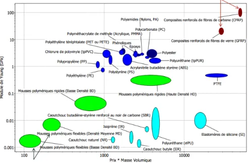
3.1 Variation of Young modulus according to a specific weight-and price growing function. . . 32
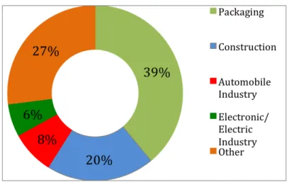
3.2 European total demand for plastics in 2012. . . 35
3.3 Flachdach Technologie, by the German company FDT. . . 35
3.5 European plastic demand by segment and polymer in 2014
((Plastic-sEurope, 2015)). . . 37
3.6 Scheme of PVC process. . . 38
3.7 Two parts of the mould and cavity (at the top) and finite contracted product (at the bottom). . . 48
3.8 Example of use of a PVC membrane. . . 53
4.1 Calendering process: PVC compound passes between cylinders. . . . 56
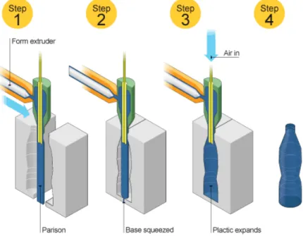
4.2 Extrusion process: PVC compound passes from the hopper to the die. 57 4.3 Blow-moulding process: particular shape is given by the mold. . . 58
4.4 Mono-axially and bi-axially oriented PVC. . . 59
4.5 Once expanded in radial direction, PVC-BO is cooled. . . 59
4.6 Circumferential direction is preferred for PVC-BO (interempresas. net). . . 60
4.7 Caption for LOF . . . 61
4.8 Different fitting ends types (Antaki, 2003). . . 62
4.9 Different pattern exist for flanging, according to the project specifi-cation and diameters (Antaki, 2003). . . 63
4.10 Transition joints (on the right) and threaded adapters (on the left) allow to associate PVC pipes with other materials (Antaki, 2003). . . 64
4.11 Different types of fittings. . . 66
4.12 Main types of walls. . . 68
4.13 Types of structured-walls for PVC pipes. . . 69
4.14 Labor and discounted cost for Drainage, Waste, Vent piping installation. 71 4.15 Labor and discounted cost for Water piping installation. . . 71
4.16 Comparison of labour and discounted cost for plastic and metallic piping systems. . . 72
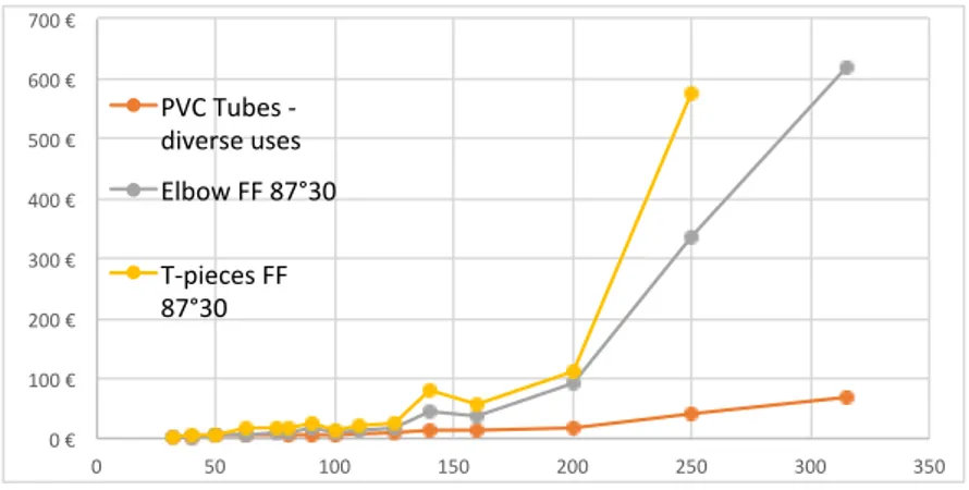
4.17 Variation of the price of PVC piping systems according to increasing diameters. . . 72
4.18 Screw leg metal clamps (left and center) for large diameters and lyre clamps (right) for smaller pipes. . . 72
4.19 Screw leg metal clamps (left and center) for large diameters and lyre clamps (right) for smaller pipes. . . 73
4.20 Examples of valves: ball valve, diaphragm valve and knife gate valve. 73 4.21 Various supports for pipes (Antaki, 2003). . . 74
5.1 Principle of the conception. . . 75
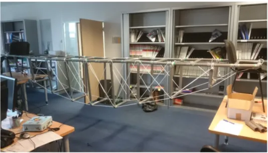
5.2 Material for the scale model. . . 77
5.3 Footbridge set with deck on the ground. . . 78
5.4 Bracing system. . . 78
5.5 Different levels of articulation of the fittings: S1, S2, S3. . . 80
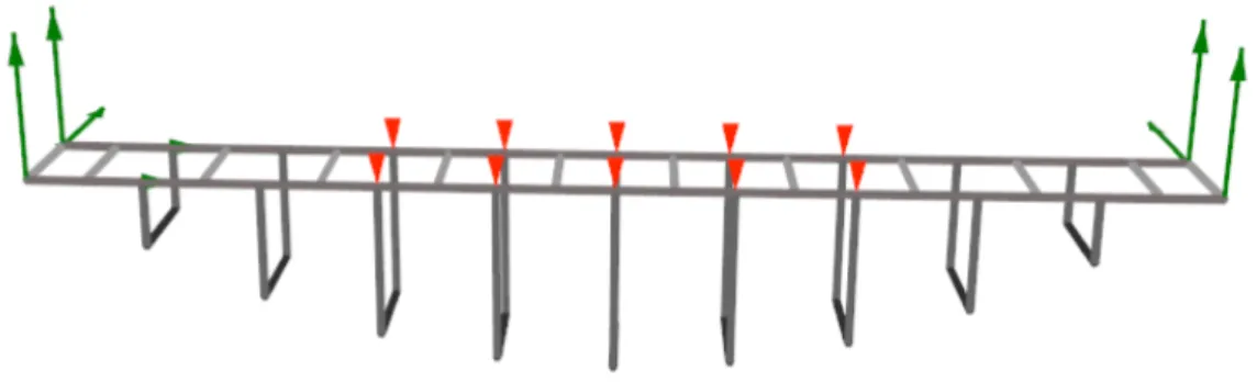
5.6 Disposition along the footbridge of the 5 points of loading. . . 81
LIST OF FIGURES xvii
5.8 Measured deflection in cm as a function of the load by plate in kg. . 83
5.9 Computed step-by-step deflection compared to measured deflection, at midspan for situation S2 and rigidities varying from 0 to 1 kg.m/◦. 83 5.10 Computed step-by-step deflection compared to measured deflection, at midspan for situation S3 and rigidities varying from 0 to 1 kg.m/◦. 84 5.11 Computed maximum deflection at midspan as a function of the rigid-ity of the articulations. . . 84
5.12 Sewing of the bracing rope along the longitudinal axis. . . 85
5.13 Alignment problems. . . 86
5.14 Geometry of the model. . . 87
5.15 Fittings (mf and ff) in the brochure Nicoll. . . 88
5.16 Flexion of the fittings: in-plane and out-of-plane. . . 90
5.17 Section of the cable used. . . 91
5.18 Criteria and results of the computation. . . 91
5.19 Stability: the footbridge is too deformable. . . 92
6.1 Dimensions of the fittings used. . . 94
6.2 Different cables supplied by Teci, from their brochure. . . 96
6.3 Cable, from brochure Teci. . . 97
6.4 A 6 m x 2.4 m panel of welded wire, with respective spacing 0.3 m x 0.1 m. . . 97
6.5 Sectional view of a reinforced concrete beam: PVC tubes are in green, reinforcing mesh is in rose, the void is filled by concrete. Overlapping exceeds 250 mm. . . 98
6.6 Wooden planking: the largest planks are on each sides, joined at their midspan by mortise and tenon. . . 99
6.7 Dimensions of the planks used. . . 100
6.8 Details of assembling on the crosspieces: screws are used to provide vertical compatibility. . . 101
6.9 Van Nissan. . . 102
6.10 "Pick-up" Nissan Navara. . . 102
6.11 Illustration of the implicit condition of Asimont’s theorema. . . 103
6.12 Flexion of a crosspieces under an axle. . . 104
6.13 Section view of the concrete supports: from behind at the left, from the deck at the right. . . 105
6.14 Top (on the right) and bottom (on the left) views of the supports. . 106
6.15 Lateral view of the supports: the footbridge lies on special hooped bearings, entirely coated with elastomer. . . 107
6.17 Assembling details of the wooden planking. . . 108
6.16 Dimensions of reinforcing cylinders and tubes for some elements: end crosspieces, deck, and inferior crosspieces (CPI) of section 1-1. . . 111
7.2 Interoperability of Grasshopper and Rhino: Grasshopper components
controls the graphical schemes in the Rhino screen. . . 117
7.3 Model of a car load: 4 vertical forces localized at the deck, and 4 torsional moments to account for the eccentricities of the wheels with respect to the edges of the deck. . . 118
7.4 Main quantities of the confined reinforced concrete section. . . 127
7.5 Geometrical quantities of the reinforcement. . . 129
7.6 Strains in the hypothesis of Navier-Bernoulli . . . 130
7.7 Geometrical quantities of the concrete section. . . 131
7.8 Flowchart. . . 136
A.1 Software interface. . . 140
A.2 Karamba workflow. . . 142
List of Tables
2.1 Comparison of steel and aluminium characteristics. . . 14
2.2 Pedestrian Bridge Data . . . 22
2.3 Pros and cons of modular structure. . . 27
3.1 Comparison of specific weights of different construction materials. . . 31
3.2 Suggestions of strain limits of plastics for engineering purposes. . . . 31
3.3 Class Requirement for PVC-U and PVC-C. . . 42
3.4 Physical properties of PVC and of different materials. . . 43
3.5 Mechanical properties of different construction materials. . . 44
3.6 PVC mechanical properties for the present work. . . 44
3.7 Long-term and Short-term design value for PVC and other materials. 47 3.8 Shrinkage ratios for different plastics. . . 49
3.9 Import and Export prices for PVC compounds. . . 52
4.1 Typical values for nominal diameters (Part I). . . 67
4.2 Typical values for nominal diameters (Part II). . . 67
5.1 Main characteristics of PP for design with respect to PVC and steel. 77 5.2 Dimentions of mf-fitting. . . 89
5.3 Dimentions of ff-fitting. . . 89
5.4 Values for the resistance of cables. . . 90
6.1 Main characteristics of weight and dimensions of the vehicles considered.103 7.1 Coefficients applied to the loads according to the nature of the limit state and the type of loading. . . 116
7.2 Maximum actions in sections and extremal linear stresses, calculated along the deck. . . 118
7.3 Maximum actions in sections and extremal linear stresses, calculated along the inferior crosspieces. . . 118
7.4 Maximum actions in sections and extremal linear stresses, calculated along the superior crosspieces. . . 119
7.5 Maximum actions in sections and extremal linear stresses, calculated along the columns. . . 119 7.6 Maximum actions in sections and extremal linear stresses, calculated
along the columns. . . 119 7.7 Deflection of the structure. . . 120 7.8 Bending resistance MRd of the elements (Deck, CrossPiece Inf. or
Sup, Columns). . . 132 7.9 Shear resistance VRd,c of the elements (Deck, CrossPiece Inf. or Sup,
Chapter 1
Introduction
The thesis work intent is introduced and put into context. The assumptions behind the project developed and the analysis methods for the study of a bridge made of a combination between plastic tubes and concrete are briefly recalled.
1.1
Background
The present work is born from an opportunity that has been given to me: a French engineering consulting company of the VINCI group, ISC offered me a stage to de-velop and expand an ambitious attempt. Working since a few years in African context (for example Oyala, tribune présidentielle, pont au Cameroun, Burkina), the firm has been confronted the difficulties that such a context raises:
(a) Materials are far less supplied than in Europe, which makes onerous import often necessary, striving up the costs and the delays;
(b) Road network is not decent, making large zones inaccessible to trucks and cranes;
(c) Most of the workers have no qualification: technological tools and materials shall be avoided.
Moreover, in the sector of construction, environmental issues find a growing reso-nance, as the necessity to find alternative materials and to integrate the environment in the design process raises.
Therefore, in 2015, with the willing to develop a relevant answer to these acknowl-edgements, ISC designed a reinforced concrete footbridge using a permanent form-work made of PVC pipes. More details are given in Chapter 2 about this project.
1.2
Aim
The first objective of the work was to find the best static scheme to realize a PVC bridge, using the parametric algorithm Grasshopper in the Rhino environment, and
then to design such a bridge. After analyzing pros and cons of the main different static systems, the footbridge has to answer to a specification note:
- Use of light materials, if possible man-handling, to avoid cranes and lifting machines;
- Use of widespread economical materials, to limit transportation and costs; - Use of durable material, suited to rustic environment; to avoid maintenance
in remote areas;
- Use of material with low environmental impact;
- Span from 15m to 25m, to beat the competition of wooden and aluminium footbridges, for spans up to 10m-12m;
It quickly resulted that the intuition ISC had a year ago was right: I was put in charge of studying the material PVC and enlarging its structural role.
1.3
Approach
The project will be done by support of structural engineers at ISC and in collab-oration with the department of architecture who has already tested a method for structurally optimized generative geometry. I have written this thesis parallel with the aim of exploring a structurally informed design process.
The main parametric tool to be used in the project is Grasshopper which is a vi-sual programming editor. As a plug-in for Rhino3D, Grasshopper is integrated with the modelling environment used in e.g. architecture and engineering. Grasshopper offers the opportunity to define precise parametric control over models, the capabil-ity to explore generative design work flows and a platform to develop higher-level programming logic by using an intuitive, graphical interface.
For structural evaluation of structures modelled within the parametric design tools Karamba will be used. Karamba is a plug-in for Grasshopper that makes it easy to combine geometric models, finite element calculations and optimization algorithms like Galapagos.
For evaluation of the structural outputs given from Karamba, the limits in terms of internal action and displacements are checked with reference to the Codes (in particular Eurocodes)
Furthermore, the models will focus on the structural and architectural concepts, which are tightly connected. This is likely where the focus on the transdisciplinary collaboration between architecture and engineering will take place.
1.4
Limitations and assumptions
Only linear elastic analysis will be performed, i.e. the calculations are based on the following conditions:
1.5 Used Software 3
1. Hook’s law is valid, i.e. the materials are ideally elastic;
2. Bernoulli’s hypothesis that the linear distribution of strain in the cross-section is retained during loading.
Furthermore, Karamba is also limited to linear elastic calculations.
- Only thin plate theory or Kirchhoff theory, i.e. a line that is straight and normal to the mid-surface before loading remains straight and normal to the deformed midsurface. Furthermore, this prohibits transverse shear deforma-tions. (Cook et al., 2002).
- Only three-node triangular element. This is a limitation in Karamba, used FE software integrated with the parametric design tools, that only work with triangulate elements.
- The structures or parts of structures that are analyzed have the same cross-sectional thickness everywhere, i.e. non varying cross-section.
- Buildability or construction method are not investigated in depth. A smaller presentation of this will although be presented for the collaboration project. - The core plug-ins but not every used plug-ins will be described in detail. This
due to that a lot of plug-ins have been used and some of them to a small extent, i.e. small influence on the overall project.
- The most important components in different plug-ins but not all components will be described in detail. For further information about all components for every plug-in the reader is referred to the manual of the program.
1.5
Used Software
The software used in the project are presented in Attachment A. Rhino3D and Grasshopper were predetermined which, in this case, are the foundation of the para-metric design tools and consequently the most important tools for e.g. defining geometries. Karamba is also one of the most essential tool in the thesis. It is a well-known FE motor within the parametric design tools.
In particular, the parametric scripts are developed in Grasshopper - Karamba while visualized in Rhinoceros. The scripts are mode of components whose proper in- and out-puts are connected through wires. This creates a very visual way of scripting, not requiring the knowledge of a specific programming language.
1.6
Thesis framework
- Chapter 2 presents basic concepts that are keystones for the new type of struc-ture.
- Chapter 3 is a state of the art for PVC: reminding the common properties and interests of plastics in general, it shows why PVC is the most pertinent plastic to be used for our scope. Its production processes and classifications are described. Specific mentions of PVC in Codes are referenced. Its mechanical and physical properties as well as its structural behavior are detailed. Project parameters such as its market and main applications are not forgotten. - In chapter 4, the same methodology as for chapter 3 is applied to semi-finished
products derived from PVC: tubes and fittings. The different ways to connect them are analyzed. Influence of their geometry on their load-bearing capacity is studied.
- Chapter 5 is dedicated to a few preliminary attempts to design a PVC foot-bridge. A scale model has been realized and loaded. Taking into account necessary refinement, a phasing has been proposed to build a full-scale PVC footbridge: it brought to light the impossibility to project a full-PVC bridge and oriented the role of PVC to the role of structural formwork.
- Chapter 6 details materials, loads and supports for the realization of a realistic full-scale PVC concrete composite footbridge.
- Finally, normative verifications according to Eurocodes are made in Chapter 7, for all the materials implemented. The software used to create the parametric FE algorithm of the footbridge are quickly presented. Their inter-operability is briefly described.
- The two Attachments deal with the used software and the drawings of the realized footbridge.
Chapter 2
A Different Way to Realize
Structures
In the first part of the work is presented an example of structure that illustrates a new way to realize structures. This structure has a PVC skeleton. That mate-rial is well-known and often used for piping systems. It offers the possibility to combine its classical abilities to contain and transport fluids and its mechanical properties, to think out structures differently. Moreover, the building sector is nowadays more and more concerned by social issues, such as green materials, low emissions, durability, recycling, modularity. A promising conception should inspire from these inspiring concepts.
2.1
Modularity concept
The first inspiring concept for this work is Modularity. It recalls to the geometrical aspects of the structure considered as a whole. This whole is constituted of initially independent and identified elements, with proper geometry and properties.
The word modular, according to one of its most common acceptation, means part with standardized units or dimensions, as for easy assembly and repair or flexible arrangement and use (Morris et al., 1969). At the same time, according to the Modular Building Institute, a modular construction can be defined as a design and construction process performed in a manufacturing facility which produces building components or modules that are constructed to be transported to a permanent building site.
As a consequence, modularity is very close to the concept of Prefabrication, which is the manufacture of whole buildings or components in a factory or casting yard for transportation to the site (Pevsner et al., 1998).
So, first of all, Modularity recalls flexibility and ease in the use of the components. It also implies standardization and standard products. In some way, it shifts the difficulty from the execution stage to the production stage: a modular structure is very interesting from the building point of view if its components themselves are easy to find, simple, quick and economical to produce. In other words, modularity
has critical prerequisites. Despite its advantages, it is often worth realize the work on site for reasons of implementation rather than prefabricate or provide tailor-made components. As stated above, this concept is at stake for all the different phases of the life of a civil structure: assembly, arrangement, use, reparation, and eventually recycling and deconstruction. Modular construction invokes building a structure with a large quantity of elements but with only a few number of different component. Diversity lies in the use rather than in the nature of the component.
Prefabrication and Modularity are already widely spread in architecture and housing construction. Entire houses are indeed nowadays built in factories and ei-ther assembled on site or transported as a whole. One of the pioneers of such global prefabrication systems was Raymond Camus (1) and its famous so called procédé Camus Delemontey (2007). (2) It largely helped to reconstruct the destroyed french cities after the Liberation. When it began to be used in the 1950s, it was very innovating with respect to other processes that were employed: Camus unified and standardized the prefabrication processes for all the components of the building, whereas before, each was realized according to a specific process. Moreover, he inte-grated all the secondary functions (f.e. pipe networks) to the civil works (concrete slabs). Obviously, it has been largely criticized ever since because of the aesthetic poorness of constructions. Today, this revolutionary system is mainly associated to some sad and gloomy building blocks of the french suburbs.
Prefabrication is of course also used in public works, for example to realize con-crete pre-stressed beams. However, for what concerns small pedestrian bridges, as it is the focus of the present work, entire prefabrication processes exist and many com-panies are able to deliver ready-to-use pedestrian bridges (i.e. Marcanterra, Maadi and Rocla companies).
A. Marcanterra Company
This company produces ready-to-use prefabricated bridges for pedestrian bridges: mixed steel-wood bridges or wooden bridges. They are dimensioned taking into account an 450kg/m2admissible load and a L/400 maximal deflection. In particular: - mixed steel-wood bridges are self-supported, they consist of a metallic frame on which are fixed a wooden plate and mixed steel and wood guard rails. Available spans reach 30m;
- wooden bridges are laminated timbers whose spans reach 6-8m for simply sup-ported bridges (depending on the type of bridge) and 30m for arch bridges. B. Maadi Company
This delivers in every part of the world poney truss aluminium bridges designed to the finite elements according to American and Canadian standards, up to 40m-spans.
(1)https://www.cairn.info/revue-histoire-urbaine-2007-3-page-15.htm (2)
2.1 Modularity concept 7
(a) Prefabricated bridges by Marcanterra.
(b) Prefabricated bridges by Maadi.
Figure 2.1: Ready-to-use pedrestrian bridges.
2.2
Examples of modular structures
Some inspiring modular structures are presented below. More than entering in technical and structural specifications than will be explained later on, the focus will be put on their modular properties: that is what makes them interesting for our scope.
2.2.1 Paper Bridge
The Paper Bridge is a structure designed by famous architect Shigeru Ban and real-ized in France during the summer 2007 by 27 students, taking part to a workshop, in cooperation with Terrell, a french engineering firm. It is an ephemera arch made of 281 paper tubes, as shown in Fig. 2.2. The Paper bridge has a single span equal to 20m and the rise about 6.5 m. Paper tubes are assembled into a trussed arch. A bracing system avoids any move and stabilizes the structure. The bridge can bear the weight of 20 people at one time, that is about 1.6 tons.
Figure 2.2: Paper Bridge structure.
The students only used the following components, delivered on site and assemble with simple tooling:
- Paper cylinders, with a diameter D = 115 mm, a thickness e = 11.9 mm (for a D/e ratio of 10);
- Steel disks (2 by cylinder) with two screw holes; - Metallic threaded rod;
- Continental net support to assemble the disks; - Metallic bracing cables.
Steel plates are used to provide rigidity to paper tubes and to ease their connections (Fig. 2.3). They have a double function: one is to allow the paper beams to be pre-stressed, and the second is to connect them. In such way they are similar to equivalent tools for steel frames. Two screws connect them to the support, to restrain their hinge behaviour.
2.2 Examples of modular structures 9
A threaded steel rod is tightened between two plates at each end of the tube so as to provide pre-stressing (Fig. 2.4a) and avoid any boning of the system. Erection is made by a crane thanks to provisional shoring (Fig. 2.4b).
Figure 2.3: Paper Bridge. Details of the connections.
Tubes of internal and external diameters 25cm x 28cm of the same type as those employed by Shigeru Ban have been tested by Terrell (Terrell, 2014) so as to de-termine the gross mechanical properties of the paper material (values of the Young modulus and of compressive and flexural resisting strengths).
The following orders of magnitude are deduced:
(a) Compressive resisting strength σc= 10 − 11 M P a; (b) Flexural resisting strength σf = 15 − 16M P a;
(c) Elastic Modulus E = 2.1 − 2.2 GP a; (d) Specific weight ρ = 0.82 t/m3.
(a) Prestressing. (b) Provisional shoring.
Figure 2.4: Paper Bridge details.
Closing remarks. Theses values place the type of paper that Shigeru Ban employed in the category of the poor construction materials. Nevertheless, they allow it to be used for structural applications. The use of paper raise obvious durability questions, despite applied costly and time-spending protective treatments:
it remains a non-durable material in exterior environments.
Shigeru Ban bypassed the main structural problem - connections - thanks to a steel frame method. But the final result quite sophisticated. Therefore setting it up takes a long time. Moreover, such a solution adds a considerable weight of steel to the structure. Consequently, the component of the Paper Bridge are not as standard as they were meant to. They had to be proceeded, even if can not be inferred that they are custom-made.
As a conclusion, coming back on the concept of Modularity, the Paper Bridge components allow for flexibility, they have standardized dimensions. Elements of few different natures were used in large quantities. Though, they are not so standard nor easy to find. Finally, erection is not very rapid. Even if this bridge has never come to a commercial scope because of these drawbacks, its modular conception is interesting. Shigeru Ban introduced a new material for structural applications. The structures satisfies the spirit of simplicity and ease. Ulterior problems of durability made design become more complex.
2.2.2 Facade of the EcoArk pavilion
The EcoArk pavilion, in Taïwan, was built by the Taiwanese conglomerate Far Eastern Group in 2010. The element of interest for our scope is the façade (Fig. 2.5a): it is made of 480000 Polli-Brick (100% PET bricks) (Fig. 2.5b), which are realized thanks to 1.52 million plastic bottles (3). Although its structure is a classical steel frame traditionally built, the façade is entirely modular. Thanks to its original design, the EcoArk façade weights 1/5 of traditional façades.
The building has a length about 130 m, its height is 20 m and it is made by 9 floors. The ground area covers approximately 4300 m2. As often for expositions (f.e. Expo2015 in Milan), the pavilion is thought to be quickly built, deconstructed and then reconstructed elsewhere.
(a) Façade. (b) Polli-brick elements.
Figure 2.5: Chracteristics of EcoArk pavilion
For what concerns the Pollibrick panels (Fig. 2.6), the main details are summarized
(3)
2.2 Examples of modular structures 11
in the following:
- Area of one panel: 2.85 m2 (162 x 76 x 38.5 cm thickness); - Weight: 63 kg (that is 57 kg/m3 or 22 kg/m2);
- Resistance: Wind pressures of 3.3 kP a and loads q of 345 kg/m2, which rep-resents a q/g ratio major than 15.
Figure 2.6: Detail of a Polli-Brick panel.
Modular structures can as a matter of fact achieve great results in terms of resistance. The ratio between the admissible load and the weight by unit area is really high. It demonstrates the mechanical properties of widespread and common plastics if they are wisely used.
From left to right, the façade is constituted of : 1. A solar PV module;
2. Solar clipping joints;
3. Nano-treated PC hard coat;
4. Prefabricated Polli-Brick assembly; 5. Fastening joints;
6. A structural sub-framing.
Closing remarks. Such pollibrick plastics offer moreover the great advantage to be recyclable. At the same time Modularity is thus a hefty argument, as it offers
facility and rapidity of supply and erection. For the façade of the EcoArk, facility, simplicity, rapidity and economy requirements are satisfied in the execution. But its components are quite sophisticated.
2.2.3 Make-A-Bridge system
The Make-A-Bridge system (Fig. 2.7) is a kit developed by the north American engineering and design firm Maadi, specialized in structural aluminium applications. This company often delivers ready-to-set-up structures like pedestrian bridges. The design is done without any welding. Transportation is ensured even in most remote areas. Only a small crane (1.6 t) is required. Setting it up is very fast: it can be done by 3 people in 5 hours. Available spans go up to 18.3 m, for 0.9 m and 1.8 m widths.
The pedestrian bridges delivered by Maadi have the following characteristics: - Self-weight: 44 − 73 kg/m2, depending on the components arrangement and
on the type of footbridge;
- Admissible variable load: for golf car is 240 kg/m2 or 480 kg/m2; - Maximal deflections: from L/500 to L/240.
The ratio q/g varies between 3 and 11: modularity has been demonstrated again a mean to design light structures and to increase significantly the part of self-weight in the total loads to bear.
Figure 2.7: Components of a Make-A-Bridge kit.
The commercial documentation on Fig. 2.8 presents the limits of use for the Make-A-Bridge system depending on their width, span, expected loading (on the left: bicycles, pedestrian and lightweight vehicles; on the right: pedestrian and lightweight vehicles (4)).
In addition, for these types of bridges a fatigue tests have been performed. A 0.61 m width and 6.1 m length Make-A-Bridge model (the corresponding area is 3.72 m2) is loaded in 3 points, according to Fig 2.9. As an order of magnitude, the uniform
(4)
2.2 Examples of modular structures 13
Figure 2.8: Domains of utilization for Make-A-Bridge solution.
maximal admissible load is:
Qmaxtot = 4.8 kP a· 3.72 m2 = 1.8 t In similar way, it weight approximately is:
Gtot= 44 − 73 kg/m2· 3.72 m2 = 165 − 270 kg
The model bends of 6.1 mm under a total load of 14 t (elastic limit), which is 8 times the uniform maximal admissible load. Ultimate force is 18.3 t, which is about 100 times the weight of the structure.
Figure 2.9: Failure test scheme.
In the end, Maadi is a skilled company in the use of aluminium for structural appli-cation. So, it is useful to recall the role of aluminium as a construction material. In
fact, Aluminium would be a very serious contender of steel for what regards struc-tural applications if its price was not so high: indeed it is often twice as expensive as steel. Here is presented a short comparison of steel and aluminium about some important design values: respective resisting - tensile - strength, Young modulus and specific weight and gross price for civil works supply. As both steel and aluminium for construction are alloys, the table only contains ranges and orders of magnitude.
Characteristics Steel Aluminium
Price [e/kg] 0.5 - 1 1 - 2
Strength [MP a] 250 - 1500 200 - 500
Young Modulus [GP a] 200 70
Specific Weight [kg/m3] 7.8 2.6 - 2.8
Table 2.1: Comparison of steel and aluminium characteristics.
As shown in Tab. 2.1, even if the mechanical properties of steel are better for struc-tural applications (between 1.5 and 3 times higher than for aluminium), it is 3 times as heavy as aluminium. That’s why aluminium is more and more used in appli-cations for which lightness is crucial. Speaking of bridges, this fact is significant as self-weight is often the main load to carry. Therefore, a reduction of self-weight could potentially be accompanied by the use of a weaker material.
Closing remarks. As matter of fact, the Make-A-Bridge system constitutes a robust footbridge. It is besides an efficient solution, as it is very simple, light, easy to deliver and to set up, in a word accessible. Thus it became a competitive footbridge for small ranges (lesser than 20 m). Its components are basic, even if they are custom-made for this application. It demonstrates the feasibility, interest and competitiveness than modularity can find for bridge applications.
2.3
Formwork concept
In this section, we focus on the specific nature of the elements that this documents aims to propose as structural elements: tubes or tubular shapes. Despite the most well-known and widespread domain of use of tubes is fluid transportation, resisting to the internal pressure may be assumed their only structural role. A wide range of tubes cover this scope. Further details will be given in Chapter 3. Basically, a tube is first and foremost a container: it contains - in general - a fluid (gas, air, water, oil). According to this, it could have the use of creating a sort of formwork system. According to a famous English dictionary (Simpson and Weiner, 1989), a formwork is an arrangement of wooden boards, bolts, etc, used to shape reinforced concrete while it is setting. On the contrary a scientific dictionary (Parker, 1984) insists in its definition on the notion of temporariness; it means a temporary wooden casing
2.3 Formwork concept 15
used to contain concrete during its placing and hardening. Whereas for a famous American dictionary (Morris et al., 1969), a formwork is not necessarily a wooden structure. It simply is the structure of boards that make up a form for pouring concrete in construction. A crucial element dealing with formworks, which appears transparently from the word itself, is the word form: a formwork makes up a form for concrete, it acts as a mold, a cast. Not only a formwork shapes the final structure. It is concrete container; it prevents it from pouring away. The use of formwork is inseparable from the use of concrete.
That being said, the most used and widespread formworks are currently made of wooden plates, bolt and supported to resist the thrust of liquid concrete, as shown on Fig. 2.10.
Figure 2.10: Examples of wooden formworks.
For every concrete elements, casting is the critical step for many reasons:
- Firstly beacuse it lasts a long period, in general 28 days, which is necessary duration for concrete to harden and be able to resist loads;
- Then because, whereas before casting any modification or adaptation can be made to structure, once casting is finished, prior orientation or decision is endorsed and definitive. Any change would involve destructing the new rein-forced concrete structure or element;
- Next, because casting needs a lot of preparation: it involves manpower, time, money, and materials. The casting material is reused as much as possible to limit the budgetary impact of this step: in this case we deal with re-usable formworks. On the contrary, they are called lost formworks. The amount of preparation that casting requires increases with the complexity and originality of the concrete element to cast; casting a rectangular slab is quite easy, be-cause it is a simple geometrical form, whereas casting a double curvature wall is much more requiring, because the desired form has to be a custom-made created footprint; what’s more it is executed with rectangular standard plates. Therefore one always tries whenever possible to take advantage of existing structure or surface to become natural formworks.
Many different types of formworks exist. For our scope, the review will focus on the modular and the tubular ones.
2.4
Examples of formworks
Some types of formworks with their properties are now presented and taken into cosideration, in order to underline which kind of elements cover a structural role during the casting of concrete.
2.4.1 Geotube panels
Geotube are principle of usable plastic panels to cast rectangular or square re-inforced concrete columns or beams (Fig. 2.11a). They are made of nylon, treated against UV radii. The two complementary part fit together to create a waterproof mold. They are obviously modular, as the system is based on assembling as many elementary parts as needed. Different dimensions are available to adapt different columns. As a matter of fact, the design dimensions have to fit which available width, so as not to overbuild the structure. Moreover, they are more than 100 times re-usable, easy to use thanks to the presence of handles, and allow for rapidity and precision in their setting up. However, it demonstrates a drawback of modular systems: they only adapt to a discrete range of situations, which correspond the available dimensions.
(a) Plastic panel.
(b) KAP formworks. Figure 2.11: Use of different formworks for casting columns.
2.4 Examples of formworks 17
2.4.2 Lost formworks
The french company Accessbat commercializes lost formworks for columns. Their formworks are made of KAP material (5). It is a composite light and resisting material which allows to cast as much as 4 m high at once. Such KAP formwork (Fig. 2.12) are therefore able to resist the internal pressure generated by a 4 m height of concrete:
pint= γc· H = 2.4 kN/m3· 4 m = 9.6 kN/m2 = 9.6 kP a
Available diameters vary by 50 mm from 150 mm to 600 mm. Obviously, the cylin-ders are impermeable, and demoulding is possible thanks to an helical metallic wire. These formworks also exist for rectangular and less conventional sections of columns.
Figure 2.12: Unconventional forms of KAP formworks
2.4.3 Spacing tubes
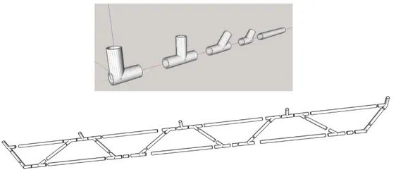
The main reference for plastic casting tools are spacing tubes, which are PVC cross-pieces. They are used to cast in situ the threaded metallic rods that maintain the correct spacing between wall formworks submitted to concrete lateral thrust. Plastic nozzles allow to seal the ends. Available diameters are (int x ext) 22 x 26 mm or 26 x 32 mm. They will then be lost in concrete when the metallic rod is removed and re-used.
Figure 2.13: Spacing tubes with corresponding nozzles.
Closing remarks. Plastics are more and more used to cast concrete as they allow waterproofing, flexibility and modularity on site. Among them, plastic tubes are about the major part. Modular formworks have already permitted to facilitate concrete casting and reduce its cost. Tubular formworks are very handy. They indeed join together both:
(5)
Figure 2.14: Spacing tubes containing a metallic threaded rod. - the possibility to contain a fluid like liquid concrete;
- the ability to resist well internal pressure, especially concrete pressure for ver-tical members.
A great domain of prospective would ally the concepts of tubularity, formwork and modularity to quickly create and set up a formwork network in which concrete would flow to fill at once the entire structure.
2.5
Case Study. An existing particular pedestrian bridge
Starting from the concepts previously explained, a special focus is hold on an existing pedestrian bridge realized in 2015 by a company named ISC, an engineering firm of the French group Vinci. Its main peculiarity is the use of PVC tubes as a lost formwork to ensure the casting of reinforced concrete and to led a more efficient design. The project and its main characteristics and information of interest are detailed below. It is necessary to state that this work is a prototype. At the same time it forces its way in evaluating the possibility to associate a structural role for PVC formwork.
2.5.1 Presentation of the project
The project was based on the belief that the main barrier to the realization of reinforced concrete trusses is casting. Even if a truss is usually one of the most efficient and material saving solution, this step would actually be too demanding and difficult if compared to the realization of an equivalent plain reinforced concrete beam. And reinforced concrete trusses references are indeed quite tough to find. This is especially true for what concerns short-span bridges (minor than 30m): at this point, the trade-off between the casting cost and the relative ease to cross such distance is always unfavourable to concrete trusses. One should always prefer using prefabricated pre-stressed concrete beams.
The underpinning key-idea of the project itself was the inspiration to use classical PVC tubes (for evacuation) as a lost formwork to make a reinforced concrete truss become competitive against other pedestrian bridges solutions, like prefabricated
2.5 Case Study. An existing particular pedestrian bridge 19
delivered concrete or aluminium bridges, or aluminium kits (f.e. Maadi, as described in Ch. 2.2.3).
PVC tubes and their connection system (as described in Chapter 3) are indeed by nature a waterproof modular system. They are designed to welcome quite pressur-ized fluids. At this point, formwork is not a problem anymore because no particular effort should be spent on :
1. connecting the basic formwork elements; 2. realizing the particular shape;
3. ensuring the sealing.
2.5.2 Requirements
The company ISC gave itself a specification notes for the project. The main require-ments for this challenge in the design are:
- Durability;
- Simple set up: composed of light materials, to ease its implementation and shall not need any lifting machine;
- Simple statical scheme: to be implemented even by unqualified workers; - Low cost: materials will be cheap and sufficiently available to limit
transporta-tion and costs;
- Adaptability: referring to rustic environment. 2.5.3 Peculiarities
This paragraph details particular design features of the project and practical deci-sions that were made necessary, even against the original spirit:
(a) The only shaping elements are plastic tubes and connections (Fig. 2.15); (b) Reinforcing bars are placed in the PVC tubes (Fig. 2.16);
(c) Self-compacting concrete has been used to make it flow more easily in the congested formwork (Fig. 2.17). In particular, concrete is poured thanks to plastic awnings into 6 holes, distributed at the top of the truss, so as it flows directly in the diagonals. Concreting is helped by the presence of shoring facilities. PVC tubes have been broken at some points to check the aspect of the concrete. It resulted to have hardened well, despite the unavoidable presence of small air bubbles trapped between the tube and the concrete;
Figure 2.15: Model of plastic connections and plastic skeleton.
Figure 2.16: Disposition of the reinforcing bars in the plastic sections.
(d) Tightening of half-shells to ensure sealing (Fig. 2.18a). In fact PVC connections had to be sliced into two half-shells so as to let reinforcing bars overlap and to allow their fastening. Metallic hose clamps are used to tighten the half-shells and avoid any concrete leak during pouring;
(e) Setting up on supports necessitated a mobile crane and a strap system (Fig. 2.18b). 2.5.4 Geometrical Chracteristics
The dimensions of the pedestrian footbridge are summarized in Tab. 2.2.
Two different materials compose the section, that is uniform for any component of the truss:
• PVC tubes, diameter Φ 200 mm, thickness 4.9 mm ;
• Concrete C25/30 constitutes the interior section, diameter Φ 190.2 mm.
2.5.5 Loads
2.5 Case Study. An existing particular pedestrian bridge 21
(a) Concreting step.
(b) Position of concreting holes.
(c) Satisfying aspect of concrete once hardened and deshuttered.
Figure 2.17: Concrete peculiarities.
- Self-weight of concrete (as permanent load): g;
- Pedestrian uniform load (as variable load): q = 500 kg/m2 (according to (Eu-rocode, 1991)).
As a tube has an interior diameter Di such as:
Di = De− 2· e (2.1)
where e is the tube thickness (4.9 mm) and De is the exterior diameter (200 mm). Assuming for the reinforced concrete a specific weight ρ = 2.5 t/m3 and computing the internal concrete area Ai, the permanent load is given by:
Ai = π 4D 2 i g = ρAi (2.2)
(a) Tightening hose clamps. (b) Setting up of the pedestrian bridge on supports.
Figure 2.18: Practical decisions.
Data
W idth w 1.00 m
Height H 1.20 m
Span l 11.00 m
Overall length L 12.00 m
Table 2.2: Pedestrian Bridge Data
2.5.6 Calculation
So as to resolve quickly the truss, calculation was done by ISC team with the finite element software Graitec Advance Design (6), performing a linear elastic analysis. Supports are placed at 50 cm of each end of the bridge, so as to get a 11 m span out of the 12 m length bridge.
2.5.7 Results of the analysis
Axial Forces. As expected because of the horizontal shape of the truss, highest normal stresses are around midspan, where bending moments are maxima. As it can be seen in Fig. 2.19a, the maximum axial force Fmax is:
Fmax = ±12.5t = ±125 kN
(6)
Graitec Advance Design is a software for structural analysis and design of Reinforced Concrete, Steel and Timber structures according to the latest versions of Eurocodes (EC0, EC1, EC2, EC3, EC5 and EC8), North American (ACI-AISC) codes and Canadian codes(A23.3, S16). http:// www.graitec.com/it/ad.asp
2.5 Case Study. An existing particular pedestrian bridge 23
The corresponding normal stress in concrete is: σNmax= Fmax
A σNmax= 4.4 M P a
(2.3) which is far below the resisting strength of a C25/30 concrete.
Bending Moments. ISC team did not manage to design a perfect truss because of compatibility problem between plastic tube connections. Further explanations and details on this will be given in Chapter 3. The fact is that the non-optimal truss, with subsequent eccentricities at nodes - truss members do not strictly converge to one node - engenders parasite bending moments in the members, as shown in Fig. 2.19b.
Maximal calculated bending moments are around: Mmax = ±14.3kN.m
They are located, as a logical expectation, at the level of the nodes. Subsequent bending stress is computed as:
W = π.D 3
32 (2.4)
σbmax= ±Mmax
W (2.5)
Therefore, neglecting the shear contribution to stress, bending contribution to stress writes as:
σb
max= ±21.2 MPa
This contribution is far from negligible. It contributed to the need of a non-linear classical reinforced concrete computation that, taking into account that maximal axial forces and bending moments are not collocated, allowed to check the sections and the structure.
As this short calculation showed, the effects of non-optimality of a truss for compat-ibility reasons are tremendous. They clearly overweight the first order analysis and become themselves critical.
Deflection. The FE element software also allowed for a rapid calculation of the midspan maximal deflection. As showed in Fig. 2.19c, at ULS maximal deflection occurs at midspan and equals 8.5mm. This is highly satisfying as, for a 11m-span it stands far above the most critical deflection criteria:
L 1300
L 500
(a) Axial Forces.
(b) Bengind Moments.
(c) Displacements. (d) Repartition of costs.
Figure 2.19: Pedestrian Bridge results.
2.5.8 Analysis of the costs
An important factor to evaluate the relevance of a statical scheme is the total cost of its production. For the studied structure, the costs of the different tasks are classified and detailed in Fig. 2.19d. The repartition is such that the total cost is divided according to:
- Formwork: it regroups the gross material (plastic tubes and connections), its sealing (with a specific plastic seal) and tightening.
- Manpower: the cost of manpower for every task is included in this task. - Concreting: includes the concrete material, its delivery on site and diverse
small equipment.
- Reinforcement: this embraces the price of steel reinforcing bars.
- Completions: contains the price of the crane to install the footbridge from the shoring to the definitive supports.
2.5 Case Study. An existing particular pedestrian bridge 25
Total costs equal 14500e. Taking into account that the bridge is 1 m wide and 12 m long, the price by unit of area is 1208e/m2. This is a quite elevated ratio, as prefabricated pre-stressed concrete bridge are available for 800e/m2. However, this number deserves a discussion.
As it has been said before, this work is a prototype: as such, it required certain unavoidable part of testing and thinking on site. Moreover, several solutions to resolve sealing and reinforcement problems have been tested, and discarded. As a consequence, the indicated total costs are obviously over-estimated with respect to a well designed process. Formwork stands for a important part of the total cost (29%) especially because of PVC connections (21%). As it will be explained in the next chapter, their price is exponential of the nominal diameter. Then, 8% (1160e) of the total price has been spent to recreate a sealing (plastic seal and tightening metallic hose clamps), because the arrangement of the reinforcing bars make it necessary to cut the connections.
It is worth notice that PVC materials costs more than concrete and steel structural components together (21% vs 14% & 5% respectively).
The final displacement of the structure after concreting and hardening costed up to 7% of total cost (∼ 1000e).
A great amount of manpower has been needed because of what was said previously: it is difficult though to evaluate the part that one could save. Though, avoiding the cut of the connections and realize a cast-on-site operation would save more than 20% of the total cost, because manpower would also be reduced. As a matter of fact, it would induce a reduction of price by unit of area ratio to around 960e/m2, which is sufficiently low to be taken into account, given the advantages such a process offers incidentally.
2.5.9 Disadvantages and Limits
The main limits of the project are summarized here: 1. Necessity to employ a crane after hardening;
As the structure had been erected on a provisional planking, the process needed a crane to move the footbridge to its final position. A great font of economy and rapidity would be to erect the PVC skeleton on the definitive support with provisional shoring if necessary and to pour concrete directly into it. Once concrete has hardened, only the provisional shoring would need to be dismantled.
2. Density of reinforcement at the nodes (Fig. 2.21);
It is due to a non-optimal design of the truss causing parasite moments. 3. Complexity of subsequent sealing;
It needs to be sealed with liquid seal and metallic hose clamps. 4. Geometrical compatibility between PVC connections;
Figure 2.20: The structure is moved to its definitive support once concrete has hardened.
Figure 2.21: Density of reinforcement.
As explained in the next chapter, PVC connections are only available for a few numbers of angles (67◦30, 87◦30, 45◦) which links the height and the length of the footbridge to the number of horizontal subdivisions.
2.6 Concluding Remarks 27
2.6
Concluding Remarks
Table 2.3 summarizes the main advantages and drawbacks or lacks of a modular structure. It has already be detailed why a modular structure was, in general, simple, easy, economical, rapid - in a word: smart - to set up.
But, in general, it can’t be hidden that they lack aestheticism. Indeed, they are not designed in that scope. This is not their specific focus. Design are often basic and above all studied to be performing. Even though the same components can be used for different modular systems.
Depending on the material, they can be as robust as that an equivalent non-modular structure. Their lightweight often make them more efficient.
The question of their adaptability depends on the context: the design of such struc-tures is completely adaptable because it only depends on assembling components. But, once the design is validated and the works have started, they give birth to quite rigid structures, because of the need of compatibility the diverse elements require.
Advantages Drawbacks
Simplicity Aesthetics
Facility Importance of the choice
Diversity of the material
Adaptability of design Adaptability on site Rapidity Appropriate/Custom-made
Economy components
Not Custom-made structures
Table 2.3: Pros and cons of modular structure.
One could have thought that using PVC tubes and their appropriate connections would have led to a more efficient design. But, problems occur with reinforcement. As it is means to deal with tensile concrete, another solution is to avoid concrete to be under tension. Therefore a further improvement could lie in a pre-stressing phenomenon in concrete members.
Geometrical compatibility problems of the piping system have raised from this project. Again, this demonstrates the drawbacks of modular systems when it comes to refinement: a wide range of solutions exist, but this range is discrete.
However, that being said, the casting of the reinforced concrete footbridge demon-strates the possibility to use plastic tubes to cast concrete. A certain number of problems has to be solved at this point so as this solution to become really interest-ing from a practical point of view.
A further improvement would be to make this modular tubular formwork able to carry to the concrete weight, until it has hardened so as to install it very quickly on site on its supports and then pour concrete into it. It would not need any lifting equipment and would limit the provided that the previous remarks are taken into
account. Determine whether this is possible is the task of the present work. This amounts to giving a structural role to the formwork in question.
As a consequence, the problematic is about the possibility to build efficiently a safe and robust concrete structure with a formwork having the following character-istics:
- structural role;
- tubular form and resistance; - modular conception.
Chapter 3
PVC: a material for civil
engineering
The objective of this chapter is to demonstrate that PVC is a pertinent struc-tural material for civil engineering applications. Reminding that PVC is part of the family of plastics, an overview of the material is proposed as it is nec-essary to fix why it is interesting to our purpose. Its physical and mechanical characteristics will be detailed, as well as its production, use and parameters. Then description will move on the semi-finished products that derive from it: different types of pipes, connections, and auxiliary elements.
3.1
Family of plastics
After the nineteenth century, the use and production of plastics were still in their infancy. Current modern plastics have only seen their first developments between 1920 and 1940. During this period were invented f.e polyvinyl chloride, low density polyethylene, polystyrene, and polymethyl methacrylate. The advent of the Second World War increased steadily the demand, mainly to substitute for materials in short supply, such as natural rubber. Large-scale production after the war combined to the founding of new types of plastics reduced dramatically their cost and allowed it to compete with classical material, such as wood, metal, leather, glass. Nowadays, they greatly contribute to reduce weight and prices of industrial products and to increase energy efficiency.
In the 2010s, there are more than 90 generic classes of plastics. These classes can be then split into 1000 sub-generic variants. Finally, plastics exist under more than 50,000 commercial denominations. Therefore, it is necessary to fix what is intended by the word Plastics and which category this work will deal with.
Among the great diversity of definitions of the word plastic, we will agree on the definition of the Collins English Dictionary (Collins, 2004): any one of a large number of synthetic usually organic materials that have a polymeric structure and can be moulded when soft and then set.