UNIVERSITÀ DI PISA
FACOLTA’ DI INGEGNERIA
Tesi di Laurea
Studio Preliminare di un velivolo PrandtlPlane
da 250 posti
Preliminary design of a 250 passenger PrandtlPlane
aircraft
Relatori:
Prof. Aldo Frediani
Prof. Dieter Schmitt
Dr. Ing. Eric Maury
Candidati:
Claudio Bottoni John Scanu
Acknowledgements
We wish to express our appreciation to everyone who has aided in this work. Particularly, to Prof. Ing. Aldo Frediani, for his general support, for his critical revision and for the constant attention dedicated in every aspect of the thesis; to Ing. Emanuele Rizzo and Ing. Tommaso Tattesi, for technical support; to Ten. Col. Porcari, for his technical assistance by collecting information and data, and to the students Marco Boni and “dott.” Giuseppe Iezzi.
Contents
• Abstract iii • Introduction iv
• Chapter.1 The PrandtlPlane concept 1.1 Unconventional configurations 1 1.2 The Best Wing Systems by Prandtl 5 1.3 A PrandtlPlane aircraft according to Vision 2020 10
• Chapter.2 Geometry Generation 2.1 Parametric geometry generation 17 2.2 MSD - CATIA® interface 26
2.3 Assembly design in CATIA® 31
• Chapter.3 PrandtlPlane Conceptual Design 3.1 Introduction and Customer requirements 36 3.2 Fuselage design
3.2.1 Introduction 38 3.2.2 Internal arrangement according 40
to AEA Requirements
3.2.3 Comparisons in term of ergonomics aspects 57 3.2.4 Comparisons in term of skin friction 73
ii
• Chapter.4 Preliminary Fluidodynamical Analisys
4.1 Aerodynamical project 86
4.1.1 Preliminary High speed aerodynamical design 86
4.1.2 Choice of the airfoils 92
4.2 CATIA® model creation optimised for the grid generator 95
4.3 Fluidodynamical analysis with the software FLUENTt® 99
4.3.1 The aerodynamical field 99
4.3.2 Choice of the computational model 100
4.3.3 Mesh validation 100
4.4 Solutions and postprocessing 102
• Chapter.5 Maximum Take Off Weight Estimation 116
• Chapter.6 Longitudinal Flight Stability 6.1 Foreword 137
6.2 Longitudinal equilibrium and stability of the PrandtlPlane 142 6.3 The PrantlPlane stability 146
Abstract
This graduating thesis aims at showing the potential characteristics of a new aircraft configuration, named PrandtlPlane in honour of Ludwig Prandtl.
In Chapter 1, the main ideas on the PrandtlPlane concept are presented, starting from the Prandtl’s problem on the Best Wing System.
Chapter 2 deals with problem of the shape generation of the PandtlPlane aircraft, to be used to carry out the aerodynamical development of the aircraft.
In Chapter 3 the design of 250 seat PrandtlPlane aircraft is shown.
The aim of this activity is not that of giveing a final design but only to show the potential benefits of the configuration and to underline the differences between conventional and PrandtlPlane configuration.
In Chapter 4 preliminary aerodynamical analysis performed on the 250 seat PrandtlPlane aircraft.
Chapter 5 deals with the assessment of the maximum take off weight.
The relationship between aerodynamical efficiency and the stability of flight appears in Chapter 6.
iv
Introduction
Passenger and cargo traffic are estimated to grow by a factor of three in the next two decades, especially along medium and long range routes worldwide. The civil aircraft of the future are requested to improve significantly their performances. Typical required performances were defined at the beginning of 90’s by the airline companies. More recent definitions of the required performances in the framework of the European Community were given in Vision 2020, by the Advisory Council for Aeronautics
Research in Europe, October 2002. This document, starting from the present state of the
art on transport aviation in Europe, defines the future scenarios in fixed wing transport and indicates the next challenges and goals of the fixed wing air transport in 2020. A brief analysis of Vision 2020 will be given in this graduating thesis.
Typical requirements for the civil air transport of the future are: more available space and comfort, 10-12% time reduction for boarding and disembarkation of passengers and luggage, improvement of cargo capacity, possibility of operating from present runways and airports, 30% reduction of Direct Operative Costs, improvement of the operative life, reduction of initial investment and costs for maintenance, 0.85 Mach cruise speed, more cargo in addition to luggage, reduced approach and landing separations due to wake vortex turbulence. In addition, new noise and emission requirements are considered to be a major concern.
The V and VI Framework European Programmes in the field of Aeronautics indicate the reduction of pollution in the atmosphere and of noise and emissions in the areas around airports as fundamental requirements for future aircraft.
The problem of reducing Direct Operative Costs and noise and emissions can be faced by using technology advancements (new materials for structures and engines, reduction of production and maintenance costs, etc). These advancements can produce only long term benefits and the trend says that a reduction of about 30% of DOCs (Direct Operative Costs) is not available in the next decades The increase of aircraft capacity is another way for reducing the unit costs in the long routes. But, in the short routes, very large aircraft cannot be used and, in the long routes, the biggest possible aircraft compatible with existing airports must be included in an 80x80m horizontal square, in order to be
compatible with present airports. So, the advantage of increasing dimensions came to its end with the A380 aircraft.
The conclusion is that future requirements for DOCs and noise and emission reductions will not be satisfied, without a significant improvement of aircraft performances.
The improvement of the aerodynamic design against drag is essential for the commercial success of any transport aircraft programme and for reducing pollution and noise. The need of improving the aircraft performances is mandatory; a 1% reduction of drag for a large transport aircraft saves 400.000 litres of fuel and, consequently, 5000 Kg of noxious emissions per year. Many national and international authorities indicate the dangerous improvement of pollution due to the aircraft’s share in global emissions. The problems of noise and noxious emissions during take off and landing produce the worst impact on people living in the surrounding areas. The improvement of the low speed aerodynamic efficiency of aircraft is one of the main challenges of the future.
The level of survivability of accidents in take off and landing is a further challenge: structural design, design against crash and fire, fuel tanks, new materials, evacuation system, etc., are of major importance in this concern.
The internal noise in cabin and the comfort of passengers have to be enhanced in future aircraft. In summary, the following main challenges need to be faced in the short and long term: high reduction of the Direct Operative Costs, cut of noxious emissions, decrease of the external noise level around the airport areas, improved safety and comfort in flight, improved survivability of accidents.
In a large transport aircraft during cruise flight, drag is mainly due to friction drag (about 47%, according to Airbus) and induced drag (about 43%), where the induced drag depends on the lift distribution along wing span. The lift distribution of today large transport aircraft is so optimised that any further significant reduction of induced drag cannot be easily obtained.
Ways of reducing friction drag are suction of the boundary layer or use of devices on the outer surface of the aircraft but, till now, the overall benefits are not well quantified. A possible jump forward in air transport will come from the introduction of completely new, non-conventional, aircraft.
The main starting property of this aircraft configuration is a strong reduction of the aircraft drag, based on an intuition of Prandtl.
According to Prandtl, the lifting system with minimum induced drag is a box-like wing (named as Best Wing System by Prandtl), in which the following conditions are satisfied:
vi same lift distribution and same total lift on each of the horizontal wings and butterfly shaped lift distribution on the vertical bulks. When this condition of minimum occurs, the velocity induced by the free vortices is constant along the two horizontal wings and identically zero on the vertical bulks. The efficiency increases with the gap between the wings. The ratio between the induced drag of the Best Wing System and the optimum monoplane with the same lift and total span was calculated before 1920 and published in
NACA TN 182, 1924. In this paper, Prandtl used an approximate procedure; a closed form
solution of the Prandtl problem was given by Frediani and Montanari, in 1999, confirming that the Prandtl results, at least in the range of the wing gaps of interest for applications, were correct. It shows that, in the range of interest of h/b in the present application (10-20%), the induced drag is reduces from about 20% to 30%. Owing to the Munk theorems, the induced drag is independent of the sweep angles of the wings and, therefore, the Prandtl concept can be applied also to transonic transport aircraft.
In honour of Prandtl, the configuration is named as PrandtlPlane.
The problem of friction drag and wave drag is still open and no definite answer is available at this stage. The PrandtlPlane configuration can be used to design a complete family of aircraft, ranging from small aircraft to wide bodies, larger than Airbus A380. All the aircraft of the family are compatible with the present airports. In fact, in the case of aircraft larger than e.g. A380, the higher efficiency of the configuration can be used to reduce the wingspan inside 80m, without drag penalty with respect to conventional aircraft. The possibility of improving the PrandtlPlane capacities beyond the largest possible conventional aircraft is one of the possible advantages for reducing drag.
The main objective of the present research activity is to develop the preliminary design of a 250 seat category PrandtlPlane aircraft. This project is also a test case for other applications of the PrandtlPlane concept
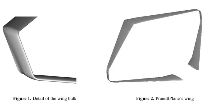
In the European Patent 716978, the PrandtlPlane configuration is similar to that shown in Figure 1, with the same fuselage of Airbus A380.
The fuselage is a wide body, enlarged vertically with three decks. In the aircraft shown in Figure 1, the rear negative swept wing shows a low aerodynamic efficiency in the segment inside the fuselage. So, in order to obtain the static stability of flight, the centre of pressure of the whole aircraft, coincident with the centre of gravity during the trimmed flight, must be closer to the front wing, which is more loaded than the rear one. So, the conditions of best wing system mentioned before are violated and the aerodynamic efficiency is reduced.
Figure 1
In the period 2000 - 2002, five Italian Universities carried out a national project, financed by the Ministry of University, to develop the PrandtlPlane configuration with application to a 600 passenger aircraft. The Universities were Torino, Milano, Roma La Sapienza, Roma Tre, coordinated by Pisa University. Technical University of Torino carried out wing tunnel tests together with Alenia Aeronautica; Technical University of Milano carried out the preliminary design and optimisation of the wing system, Roma La Sapienza and Roma Tre carried out the overall optimisation of the aircraft. The most important result of the project was the solution of the conflict between aerodynamic efficiency and stability of flight and the configuration became completely different as shown in Figure 2. In the new solution, the fuselage is enlarged horizontally with a single deck for passenger and with a constant width up to the end. The rear wing is positioned over the fuselage and connected to it by two fins.
This aircraft is stable in cruise flight, the margin of stability can be controlled and modified and, at the same time, the lift is equal on the front and the rear wings. This result is the consequence of the high aerodynamic efficiency of the central wing sector of the rear wing, (between the two fins), which depends on both the gap and the shape of the
viii top fuselage or, in other words, on the characteristics of the aerodynamical channel, defined by top fuselage, bottom rear wing and lateral fins.
The main characteristics of the PrandtlPlane configuration of reference emerge in the following chapters .
Figure 2. A first possible 600 seat PrandtlPlane with two fins
This thesis analyzes at a preliminary stage an application of the PrandtlPlane concept to a 250 seat aircraft.
A 250-300 seat aircraft of future generation could be interesting to develop the continental and intercontinental aircraft transportation at lower cost than actually.
At the beginning of this activity the question was: “is the PrandtlPlane concept able to generate a high efficiency 250-350 seat aircraft ?”
The final answer to this question is not available, because one needs a final design (wich is not possible now) and a multidisciplinary optimization (wich could be possible only after some time). Anyway this thesis shows that the PrandtlPlane configuration is flexible as far as the passenger accomodation is concerned and, besides, it allows us to transport a very large amount of containers, say, more then the double of an equivalent conventional aircraft.
The large cargo deck is possible because of the small height of the front wing box (the half of a conventional aircraft) wich crosses the fuselage under the same cargo floor and,
also, to the large width of the fuselage, necessary to fulfill the PrandtlPlane aerodynamical requirements.
The main positive aspects also the possible problems of the configuration are indicated in this thesis.
The PrandtlPlane concept
1
CHAPTER 1
The PrandtlPlane concept
1.1
Unconventional configurations
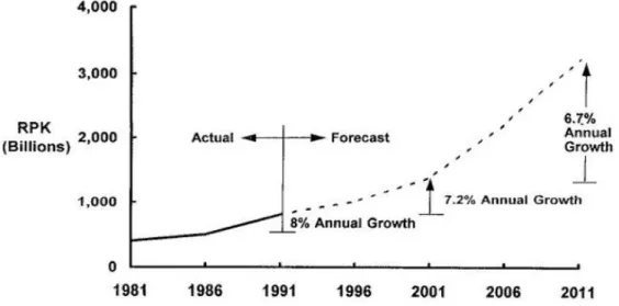
A study by British Airways in 1993 [1], related to the air traffic prediction of the following decades has estimated an increase rate exceeding 6% per year (Figure 1) with peaks for international links.
Figure 1. Estimated growth of air traffic on medium and long range routes in the next future
The increase of the dimension of the liners was recommended to the aircraft manifactures (the Airbus A380 is the result of this strategy).
Future aircraft have to be designed with the following requirements.
Commercial requirements: better control of passenger “status”, much available space, less vibrations, better choice of on-board activities, less constraints (unpleasant conditions) by boarding and getting off . The time for loading and disembarcation of passengers should be reduced by 10-12% with respect to the current mean times (about 120 minutes). The single bridges must be quickly reset to allow for enhanced operational flexibility.
Economic requirements: reduction by 20% of the direct operative costs (DOC). This can be achieved by a reduction of the fuel consumption per passenger per km, an increase of the operational time-span and lesser investment and maintenance costs, etc.
The PrandtlPlane concept
Requirements on environmental impact: the noise level must be significantly reduced and the atmospheric pollution cutted.
The current development of traditional configurations has reached such a level of optimization that, in spite of enormous technological efforts, only small additional benefits can be achieved.
These considerations motivate modern aeronautical research towards the study of non conventional configurations.
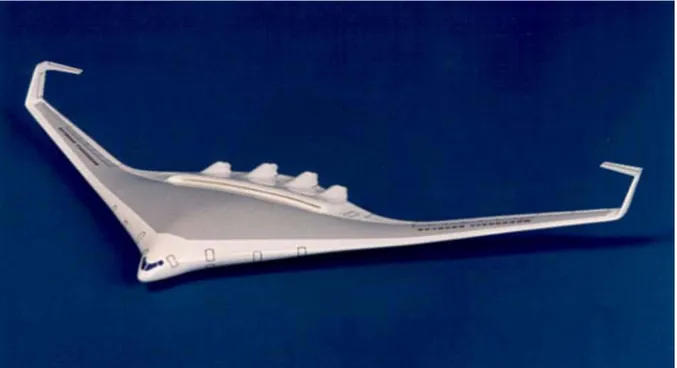
Figure 2. Blended wing body
Figures 2 and 3 show one of the non conventional configurations which has been most intensively studied since World War II, the so-called Blended Wing Body (BWB)
Figure 3. Horten 7 (German experimental prototype).
The PrandtlPlane concept
3 - Saving of 50% of the so-called parasitic drag, because of the lack of a real fuselage. - Very high aerodynamical efficiency in cruising conditions, compared with traditional
architectures.
- Small bending moment along the span in cruise flight, by means of a proper load distribution.
On the other side disadvantages are:
- Large aircraft have a span larger than the admissible one (80 m) - Engine integration.
- Stability of flight. - Flight controlin pitch.
- Low structural efficiency due to pressurization. - Flight quality in roll.
- Evaquation problems in emergency, etc.
- Modest flexibility in the load options especially in low density configurations, because of heavy restrictions both in axial and side directions;
Figure 4.McDonnell-Douglas Blended Wing Body concept with C-wing tips
Figure 4 shows the addition of C-Wing tips to the McDonnell-Douglas Blended Wing Body concept [3] . The addition of these wings tips would permit the BWB configuration to
The PrandtlPlane concept
improve the stability of flight. Although many details have to be defined the addition of C wing tips seems to be promising as far as controllability and efficiency are concerned.
A further non conventional configuration, is the Prandtlplane, so called after the German physicist Ludwig Prandtl (1875-1953) who first tackled the problem of the minimum induced drag in a lifting system. The results of Prandtl’s studies had no impact on the development of aviation because the biplane aircraft presented a total drag larger than that of monoplanes, due to cables and trusses and, at the same time the monoplane configuration made use of the new aluminium alloys for the box structure.
The PrandtlPlane concept is a practical application of the Best Wing System theory, by Prandtl in the ‘20s [4].
The PrandtlPlane concept
5
1.2
The
Best Wing System by Prandtl
In cruise conditions the induced drag is about 43% of the total drag, the rimaining being due to friction drag (about 47%) and to the wave drag. In case of a mono-plane configuration it is well known that the minimum induced drag corresponds to an elliptical distribution of the lift forces. In modern aircraft the wing span is improved and winlets at wings tips are used to , reduce the induced drag. In 1924 Prandtl [4], showed that a lifting system exists (a Best Wing
System) with the minimum induced drag among all the lifting systems with the same span
and total lift. This configuration is a biplane with straight wings, parallel and lying in a plane normal to the flow direction, with their tips connected by two vertical and properly shaped surfaces, so as obtaining a boxed shaped wing system. Due to the Munk theorems, the sweep angles of the two wings do not modify the Prandtl results, so that the PrandtlPlane concept can be applied to transport aircraft in transonic and supersonic condition too. In the paper of Prandtl, an approximated procedure was used (without any other information).
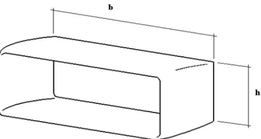
Now we recall some useful results on multiplanes, for convenience sake. The induced drag, Dm, of a monoplane is the following:
(2.1) 2 2 b q L Dm = π ,
where q is the dynamic pressure, L the total lift and b the wing span. The induced drag of the biplane can be expressed as the sum of the self-induction drag of both the wings (the same of Eq. (2.1)) and the mutual induction drag. Denoting the wings with subscripts 1 and 2, and with obvious meaning of the symbols, the induced drag of the biplane, Db, results:
(2.2) ⋅ + + = ⋅ + + = 2 1 2 1 2 2 2 2 2 1 2 1 12 22 11 2 1 2 b b L L b L b L q D D D Db π σ .
The term σ indicates the mutual influence coefficient and depends on the geometry of the system. A rigorous expression for σ does not exist, but only numerical approximations are available. In the case b1=b2=b (very important in the practise) Db is minimum and
The PrandtlPlane concept (2.3) b h 3 . 5 1 1 + = σ ,
for values of h/b in the 1/15 to 1/4 interval. In general, denoting L = L1 + L2 the total lift,
r = b2/b1 the ratio of the wing openings (0 ≤ r ≤ 1), letting L2 = Lx, (hence L1 = L(1-x)), one
obtains from the condition dDb/dx = 0:
(2.4) σ σ 2 1 − + − = r r r x ,
and from Eq. (2.2) one finally obtain:
(2.5) + − − ⋅ = σ σ π 1 2 1 2 2 1 2 min r r r qb L Db .
Hence the induced drag of a biplane is minimum when r is maximum in the interval [0-1], or when r=1. In this case, from Eq. (2.4) one obtains x=1/2, or in other words, the minimum is reached when the lift is equally distributed in the two wings (L1=L2=L/2).
The expression (2.5) for the minimum induced drag of the biplane becomes:
(2.6) 2 1 2 1 2 min σ π + ⋅ = qb L Db .
The ratio κ = Db/Dm, referred to as efficiency of the biplane is obtained from Eq.s (2.6) and
(2.1) with b1=b and becomes:
(2.7) 2 1 σ κ = + = m b D D ;
The PrandtlPlane concept 7 0.5 0.6 0.7 0.8 0.9 1 0 0.05 0.1 0.15 0.2 0.25 0.3 0.35 0.4 0.45 0.5 h/b Db /Dm
Figure 1. Optimum efficiency of the biplane versus h/b.
The optimum biplane is more efficient than the optimum equivalent monoplane and, given the wing span, the induceddrag decreases for larger spans, h.
An optimum three-plane exists; the efficiency of the optimum three-plane is better than that of the optimum biplane. And so on up to an infinite-plane. The best infinite-plane is equivalent to a box plane in wich the vertical wings generate the same tip vortex distribution of the infinite plane.
The PrandtlPlane concept
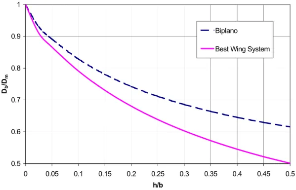
This system is the Prandtl Best Wing System when the lift distribution along the vertical wings is butterfly shaped. The Prandtl result is shown in Figure 3.
0.5 0.6 0.7 0.8 0.9 1 0 0.05 0.1 0.15 0.2 0.25 0.3 0.35 0.4 0.45 0.5 h/b Db /Dm Biplano
Best Wing System
Figure 3. Efficiency of biplane and of Best Wing System versus h/b.
So, in the case of h/b=0.15 the induced drag reduction of the Best Wing System with respect to the equivalent monoplane is about 27%.
Recent results [6] allowed to gain the following results:
- On the horizontal wings, the liftdistribution can be split into a constant and an elliptic contributions.
- The lift is equally distributed on the two wings.
- On the bulks the lift distribution is linear, with the load directed outwards in the upper part and inwards in the lower part.
- There is an optimum ratio of the value of the lift at the wing extremity (Γmin) to the
The PrandtlPlane concept
9 Figure 4. Ideal lift distribution on the boxplane
The PrandtlPlane concept
1.3
A PrandtlPlane aircraft according to Vision 2020
This thesis aims at showing the preliminary design of a PrandtlPlane aircraft, to be assumed as the prototype of a new family of medium size aircraft with high load capacity and high flexibility of use.
The aircraft is made of two swept-wings, with opposite sweep angles, connected at their tips by aerodynamical surfaces.
The importance of the lateral wings has been already shown from the aerodynamical point of view. The structural design of the lifting system is well underlined so far.
Infact, the lateral wings transmit internal loads from a horizontal wing to the other and provide cynematical links between them (Figures 1 and 2).
The fuselage is enlarged horizzontally. The rear wing is positioned over the fuselage and connected to it by two fins.
The front wing crosses the fuselage under the cargo floor and, the cargo compartment is wider than in every other conventional civil aircraft.
Figure 3 illustrates the reference configuration which was studied (only at a preliminary stage) to prove the feasibility of the project.
The PrandtlPlane concept
11 Figure 3.PrandtlPlane
The PrandtlPlane concept
The number of parameters wich define this configuration is much larger than in the case of conventional configurations with the consequence that a wither range of options are available and the possibility of optimization are improved.
From a structural viewpoint, the PrandtlPlane concept presents many possible advantages with respect to traditional configurations. The most important are:
- The total wing span is limited with respect to a traditional configuration without drag penalty and the aeroelastic problems are less severe, even if the local stiffness is smaller (however, more research is needed on this topic).
- The wings of this configuration are characterized by a weight reduction due to the possible intensive use of composite materials, combined with the absence of the attachments of the engines (in the configuration with the engines in the rear fuselage) and of the main landing gears.
- The transmission of the lift forces to the fuselage occurs through an overconstrained attachment, with a variety of paths. This property has a great importance on fatigue. - The problem of the divergence of the wing with negative sweep angle can be solved by
the stabilizing effect of the wing with positive sweep angle, connected to the first one at the tip;
- In cruise conditions, the lift forces are distributed between both the wings, nearly in the same amount.
- The fuselage is equivalent to a doulby supported beam, the supports being the front and rear wing attachments; so the fuselage bending moments are zero in the connection between fuselage and wings, contrary to conventional aircraft and, during touch down, the fuselagebending stresses relax the stresses in flight.
In optimum aerodynamical conditions the lift is equally distributed among the two wings with the maximum advantage in terms of drag . This conditions may be achieved with a proper ratio of the two lifting surfaces , with a suitable choice of the profiles and links, and by taking better advantage of the high aerodynamical efficiency of the central wing sector of the rear wing (between the two fins) due to the aerodynamical characteristic of the channel defined by the top fuselage, bottom rear wings and lateral fins.
- A very general kind of longitudinal control can be realized with pure pitching moment or with a moment associated to lift forces (for example with the elevator positioned on the front wing as in the canard configuration), by means of opposite rotation of surfaces on the front and rear wing. Such a control surfaces would be of reduced size, thanks to the large arm of the couple.
The PrandtlPlane concept
13 Figure 4.PrandtlPlane longitudinal control system
- The lateral control can be obtained by means of control surfaces set on the two fins and on the wing bulks.
The lateral stability can be controlled by the presence of diedrical angles of both the upper and lower wings. The wing bulks give a stabilizing contribution to the side-directional dynamic.
The eigenmodes of the aircraft are completely different from conventional aircreft, with positive effects on the internal comfort, noise on passengers and also on the flight qualities
- The ailerons could be positioned on the rear wing; they could be use as flaperons; in this case both the wings are fitted with high lift devices along the whole span (slats and flaps), and the condition of Best Wing System coul be obtained also in take off and landing with lower noise and noxious emissions.
- The flaps will extend over a smaller fraction of the chord because they will be distributed for a large opening along the wings. Consequently, the feedback systems of the control surfaces will be simpler and the low speed configuration more favourable than in conventional aircraft.
- The fuel can be loaded in both wings. The control of fuel consumption allows the control of the attitude of flight of the aircraft.
- The architecture of the Prandtlplane implies a new design of the main landing gear which must be positioned in nacelles beside the fuselage. The main landing gear is
The PrandtlPlane concept
made of many legs with many wheels of small diameter which can be contained inside a bay between two subsequent fuselage frames.
The current research stage on the PrandtlPlane aims at studying the large potentialities of the present configuration.
The present work aims at providing a preliminary scaling for a aircraft configuration for goods and for 250 passengers or more, as a first step of a future industrial applications to the civil transport aviation of the next decade, considered of a strategic importance for the next future market.
The PrandtlPlane configuration has the potential for achieving, all together, the top levels objectives identified by the European project Vision 2020 :
The challenge of low emissions and noise towards the quite aircraft
The objective of a substantial reduction of pollution and of a decrease by 50% of the noise perceived at the boundaries of the airfield may be reached with a synergic action in several domains, which include weight reduction and use of new propellers.
This objective can be obtained for the PrandtlPlane thanks to the pretty high values of CL
which can be achieved with a high lift device system extended on both wings in the take-off and landing. So smaller propellers can be used with smaller emissions. Besides the vorticity released by the PrandtlPlane into the field is reduced with respect to a conventional aircraft. The large hull capacity would allow, in principle, to set H2 or CH4 tanks for the possible
adoption of propellers of advanced conception.
The challenge of safety
The final objective is reducing the frequency of accidents by 80% in spite of a three-fold intensity of air traffic, operative 24 hours a day and in every meteorological condition. The following design features of the Prandtlplane make it a good candidate to satisfactorily reach the objective of:
The PrandtlPlane concept
15 - Pitch Control by means of pure couple improves safety close to the ground.
- Control is also guaranteed by large angles of attach, thanks to the large aerodynamical stability of the rear wing;
The challenge of quality and affordability
The following objectives are linked to such an aspect:
- Wider choice options for the passenger. Beside the price of the ticket, this depends on the time necessary to reach destination (including the time spent in the airport), from the availability of particular services, from the space availability on board and board activities, from an enhanced comfort index. The larger size of the fuselage and the enhanced comfort on board of the Prandtlplane reduces the economy class syndrome. - Reduction of the flight costs, thanks to the reduction of the costs of the aircraft,
maintenance, crew, fuel and for the flight taxes and parking. Reduction of the latter ones depends also on reduction of the grounding time. This can be obtained by the Prandtlplane thanks to the less time spent for boarding and landing operations for goods and passengers as it will be illustrated in Chapter 3.
The PrandtlPlane concept
References
[1] R.J. Acton, British Airways’ Requirements for a New Large Airliner, presented to the Royal Aeronautical Society, October 1993.
[2] Torenbeek E., Synthesis of subsonic Airplane Design, Kluwer Boston Inc., Hingham,Maine 1982
[3] www.desktopaero.it (C-wings design by Ilan Kroo)
[4] L.Prandtl, Induced Drag of Multiplanes, NACA TN-182, 1924.
[5] E. Pistolesi, Lezioni di Aerodinamica, Vallerini, Pisa 1924
[6] A.Frediani, G. Montanari, Problemi di minimo della resistenza indotta in sistemi
portanti chiusi, Graduate thesis in Mathematics, University of Pisa 1998.
Geometry Generation
20
CHAPTER 2
Geometry Generation
2.1 Parametric geometry generation
The preliminary aerodynamical design of the present aircraft is carried out by means of a
CFD (Computational Fluid Dynamics) code and relies upon the computer to solve the
equations of a flow around a body, with computational volume, made of cells. The three main phases of a CFD analysis are:
- Generation of aerodynamical model and the relative computational domain. - Generation of the surface volume grid.
- Computation of the aerodynamical field and analysis of the results.
The generation is made by defining a proper number of parameters to be changed during the development of the configuration. The grid generation cannot be made automatically but we need to refine the mashes according to the aerodynamic force gradients.
In the present analisys additional constraint was the limitation of the computational power, wich limited the number of cells.
In general, the generation of the aircraft shape and that of the grid are consecutive and distinct processes. This aspect is important due to the need of modifying the configuration; in these cases it must be possible to generate quickly a new geometrical model and its conforming grid.
At the At the Department of Aeronautical Engineering of the Pisa University a code named
MSD (Multibody Shape Design) was realized; it was a MATLAB® environment. MSD is a fully parametric tool, dedicated to geometry generations for CFD simulations. The parametric features and the flexibility of this tool will allow a remarkable time saving in the realization and change of geometrical models. The same operations, made with modern CAD (Computer
Aided Design) packages, like PRO/ENGINEER® or CATIA®, require a high degree of experience from the operator and, in any case, do not allow the same speed in modifying the parameters. The MSD package uses a dynamic database of cross sections and profiles. Using modular functions, geometrical surfaces and links between the several parts with splines of
NURBS type are used. The re-shaping of the geometry with a variation of the parameters
Geometry Generation
are constructed simply by stretching the cross sections or the airfoils available in the database along properly defined directional lines in the 3D space.
MSD allows to export the surface grid both in DAT and IGES formats, so that the same file
can be used both for generating structural meshes and also volume grids for aerodynamic analyses. The software makes use of some implemented GUI (Graphic User Interfaces) for handling friendly the design parameters. Axial Symmetric bodies are generated section by section. The body is also divided into an upper part and a lower part, separated by a side line, that is the line defining the lateral contour of the body over the XY reference plane. The center line is the curve of the origins of the local coordinate systems. The control section lines define the body shape along the longitudinal direction. They are obtained from a normalised section curve, that is a curve defined in an unit square and stretched, by a proper choice of parameters, to the selected shape. The basic geometry of the body is obtained by positioning a set of control section lines along the longitudinal axis in order to fit the intersections between the support lines, previously defined, and the plane of the control section line. Once the skeleton geometry has been defined, a set of regions between two contiguous control sections, called bay, is identified. Now, is possible to generate a parametric number of intermediate control sections in the bay, by linear interpolation. It can be pointed out that this kind of body generation allows to define also a primary structured grid on the body surface, by defining the number of sections and the points in the sections; a typical result is shown in Figure 1.
Geometry Generation
22 The generation process of the wings is similar to that for the body. The wing is created by adding bay to bay, from the first to the last airfoil. The airfoils are defined by: sweep, twist, dihedron and are referred to the main reference system of the wing itself. All the intermediate points of the wings are obtained by interpolation between the first and last airfoils of the bays. Each bay can be generated by extrusion, where the leading edge line, in Figure 2, defines the direction of extrusion.
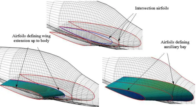
The holes considered here are defined as intersections between a wing and another wing or a wing and a body. The hole is generated by a wing, which is considered as the penetrating object and another wing or body which are the penetrated objects. The first step of the hole generation process is that of defining the traces of the penetrating object on the structured grid, on the surface of the penetrated body. This result is a closed curve or profile, relevant to the projection of a wing over a body. The second step of the procedure is the modification of
Geometry Generation
the surface grid of the penetrated object. Once a projection is obtained, the structured grid of the body surface is locally modified by doubling a body generatrix into the upper and lower branch of the intersection profile.
Fillet are objects joining wing to body or wing to wing. A wing to wing fillet is simply created using linear interpolations between the two airfoils to be joined. In the case of wing to body fillet, the generation is more complex and besides, for aerodynamic reasons, an operator needs to control the smoothness of the fillet in an accurate way. The shape of a wing to body fillet can have a remarkable influence on the local aerodynamic field, especially in the transonic range. The code MSD can allow one to join wing to wing without and with fillet; in the first case, the hole in the body is introduced by the prolongation of the wing and, in the second case, a second larger hole is generated on the body surface. This last hole is the fillet contour on the body and it is obtained by an auxiliary bay. The auxiliary bay is obtained by a linear interpolation between the wing root airfoil and an auxiliary airfoil positioned inside the body (in the symmetry plane, for simplicity sake); the trailing edge of the auxiliary bay is the prolongation of the wing trailing edge. The auxiliary bay allows us to final contour of the fillet on the body. Of course, the root airfoil of the auxiliary bay is generated independently of the wing characteristics and it is varied until a satisfactory fillet contour on the body is obtained by the operator (Figure 3).
Geometry Generation
24 Once the airfoil on the wing and the contour on the body are generated, the fillet surface has to be defined. For this generation, we use the NURBS. The fillet surface is obtained by means of the NURBS curves; they are the root wing airfoil, the hole wing/body and the hole auxiliary bay/body, including inside the previous one. So, for any curve, three points are defined on the three curves, as shown in Figure 3. The control polygon of each curve is composed by three points: the start point on the wing root airfoil, central point on wing intersection profile with body and the end point on the hole generated between wing root auxiliary bay and the body .
Problems encountered during the present work were:
- The reconstruction of the structured grid close to the intersection profile is particularly difficult and a robust interpolation tool is necessary. The standard interpolation tools of
MATLAB® could bring to a bad quality of the grid, owing to the mathematical instability of the splines, when the interpolation points become too close each other. In order to solve these instability problems, the NURBS (Non Uniform Rational B-Splines) will be introduced.
- The function foreseen by the designers of the code MSD for generating surface grids turned out in the impossibility of generating interface files IGES compatible with the
GAMBIT® software for generating the computational grid.
The problem is related to the fact that the surface of the solid is transferred from the MSD as a set of regular rectangular panels and a set of points. This problem has been solved in the new code release.
Geometry Generation
Geometry Generation
27
2.2 MSD - CATIA
®interface
The problems found in the geometry generation with MSD software, forced us to use a different procedure, while awaiting the new release of MSD.
The procedure used consisted into defining the geometry with MSD and importing it into a modern CAD as a cloud of points.
The generation of the surface was realised by CATIA software through the following operations (for example limited only to the fuselage).
1. Reading of IGS file coming from MSD as a cloud of points in Digitized Shape Editor of CATIA® environment.
2. Dissection of the cloud of poits with as many longitudinal cross-sections as the frames
employed in the MSD for the generation of the surface in the environment Quick Surface
Reconstruction
Geometry Generation
3. Generation of new frames as cross-section plot between the crossplanes and the dot-clouds
Figure 3. Curves from section Figure 2. Clouds sections
Geometry Generation
29 4. Generation of surfaces, of holes, and links in environment Wireframe and Surface
Design
Figure 4. Fuselage’s Loft
Geometry Generation
Moreover, the above procedure can be made automatically; in fact, it is possible to transfer the matrixes of dots, which identify geometry, as EXCEL® files from the MSD code. Suitable tools of CATIA® are able to read these matrixes.
Geometry Generation
36
2.3 Assembly design in CATIA
®The PrandtlPlane aircraft has been assembled in a modular way by CATIA®;this allows us to modify the single components indipendetly.
The assembley of the whoole aircraft has been realised in Assembly Design of CATIA®and it is made of the sum of subassembled parts (CATproduct files) which, in turn, are defined by elementary parts (CATpart files) ) in which the single details are represented.
The complexity of the structure of the general assembled is sumarized by the logical tree in Figure 1.
Figure 1. Main Assembly’s Logical Tree
Each component is referred to the same co-ordinates system; hence, a file of reference-frames is created in advance for the single component to be transferred into the assembled aircraft.
Geometry Generation
By means of the Existing Component function, the subassembled parts have been correctly transferred by means of the Snap function, as shown in the example of Figure 2.
Figure 2. Assembling procedure
The final check of a single assembled part is the interference check, an analysis of interference among the various components has been done.
The total result is a check, with a certain accuracy, of the amount of the space available on board, also through the introduction of manikins in the most critical areas.
The creation of these models has been made possible in Ergonomic Design and Analysis environment, exploiting the Human Builder function.
1 2 3
Geometry Generation
38 Figure 3. Manikin Generation
Figure 4. Manikin use for ergonomic analysis
Geometry Generation
Geometry Generation
40
References
[1] Gasperini M., Lugli R., Saporito G., Strumenti per la generazione semiautomatica di
geometrie tridimensionali e grigle di superficie per l’analisi CFD, (instruments for
tridimensional geometries and surface grid authomatic generation for CFD analysis), Aerospace Engeneering Department of Pisa.
[2] Frediani A., Gasperini M., Saporito G., Development of a geometric and
aerodynamic grid generators for innovative aircraft configuration, Department of
PrandtlPlane Conceptual Design
CHAPTER 3
PrandtPlane Conceptual Design
3.1 Introduction and Customer requirements
A civil aircraft is designed to satisfy operative, commercial and safety requirements.
The aeronautical designing process is an interative process with a growing complexity in which, starting from the requirements, a preliminary definition of a set of possible solutions is carried out.
The design process can be divided into three phases: conceptual design, preliminary design, detail design. The conceptual phase is developed by a few people with a deep experience in different fields of aeronautics and with good ability in planning and management. They identify the aims to be reached concerning loads and services and obtain the final definition of an acceptable aircraft; these results are obtained in relatively short time and with a minimum engineering engagement.
The preliminary designing phase requires a massive use of statistical and semi-empirical models.
These models summarize an important and expensive knowledge gained, rarely available outside the factory and characterized by quickness in foreseeing and ability of managing a higher and higher number of parameters in order to define the weight.
During the initial phases, in which geometry is only vaguely outlined, very simple models with rough prediction will be used. These models are the result of procedures that manage few parameters (called First class by some authors, like Roskam).
After this preliminary stage the aircraft configuration is improved, to check if the limits fixed by the conceptual design are respected; more sophisticated predictive models ( of second
class) could be used. The main parameter to be determined is the take off weight, that is the
sum of all the weights of the elements of the aircraft, of the fuel and the paying load. The empty weight and the fuel depend on the take off weight and,hence, more iterative estimations are required to assess the final result.
During this phase the aspects concerning Aeroelasticity and fatigue are also taken into account and care is taken in the manufactoring of some structural elements of major importance; the final result is the so called Preliminary Design. Different configurations can be examined on the light of direct operative costs and fulfilment of the design requirements, until a final solution is identified. During the third phase of designing, the Detail Phase, the
PrandtlPlane Conceptual Design
42 components that must be produced are elaborated: each particular is designed to be produced according to the previous fixed constrains in terms of weight and global geometry.
Once completed the above phases, the activities concerning manufacturing, tests and initial delivery, are developed.
The architecture of a today civil aircraft is practically defined following the experience gained in the past on similar aircraft. In the case of the Prandt1Plane the conceptual design can not make use of statistical data and tests in the same way of a conventional aircraft; anyway, in order to give a preliminary definition of the aircraft, some tools are used even though some modifications are applied when needed, as shown later on. The main goal of the present chapter is to define a possible architecture of the fuselage, in order to obtain a first prediction of the take off weight (in Chapter 5), starting from the following initial requirements:
- 258 passengers in two classes (business and economy); - medium-long range aircraft (typically 6000 n.m.); - large cargo capacity;
- sea level airports;
- takeoff runway length: 3000 m; - cruise altitude: 10500 m.
Other solution with more passenger have been also defined, with the same external shape of the 258 passenger solution. This preliminary analysis is carried out in order to show that PrandtlPlane aircraft is flexible in use.
PrandtlPlane Conceptual Design
3.2 Fuselage
Design
3.2.1
Introduction
The fuselage is the shell which contains the paying load, to be transported to a certain distance, at a certain speed and, with a given internal comfort and flight quality for passengers .
In the Vision 2020 of the European Community, already mentioned, a requirement for future aircraft is the presence of a larger air volume available per passenger. In this prelimimary analysis of PrandtlPlane aircraft the fuselage has been concepited in such a way to allow more space available for passengers and more good and laggage than in a conventional aircraft. Another important goal of this proposal is to obtain a quick loading and unloading of passengers, goods, laggage and refuelling. The solutions proposed are preliminar and enclosed in the Vision 2020 context, as possibilities for future aviation. As a matter of fact, it is well known that a typical design criterion is to use the minimum diameter, that is the diameter strictly necessary for drag reduction. The present preliminarly proposal intends to apply this criterion as a case study of the PrandtlPlane aircraft (as we will show later on) even thought a smaller fuselage is possible in framework of the PrandtlPlane configuration.
Figure 1 shows the drag coefficient vs. λF=
Fus Fus
L
φ ratio, where Lfus is fuselage’s length and Φfus is fuselage’s diameter. It is useful to fix a general trend and aligned with what said
above; it definitely suggests a further observation: the current values of λF, 10-11, underline
the importance given , also and mostly, to other considerations.
A smaller fuselage confirms to the traditional deriving criterion, due to Prof. Torembeck: “the fuselage should be designed from the inside outwards and the skin should envelop the
load in such a way that the wetted area is minimum, thus avoiding breack away of the airflow as far as possible”.
PrandtlPlane Conceptual Design 39 CD0 λF= Fus Fus L φ CDfrontal 0.04 CDwet 0.02 2.5 4 λF
Figure 1. Drag coefficients of streamlines bodies of revolutions at low speed
at zero angle of attach neglecting the upsweep angle contribution
- CDfrontal is the drag parameter due to the frontal area of the fuselage that grows up for slim fuselages
- CDwet is the drag parameter due to the wetted surface of the entire fuselage that decreases for slim fuselages. Transiction at nose Re=107
1
PrandtlPlane Conceptual Design
3.2.2 Internal layout according to AEA Regulations
Fuselage
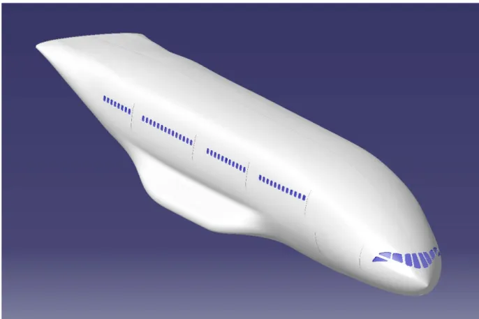
The shape of the fuselage is related to mission requirements, to wing configuration adopted and results as a compromise between requirements of aerodynamics, structures and ergonomics (Figure 1).
Figure 1. A possibile fuselage for PrandtlPlane
The aerodynamical efficiency of the wing system depends on the non dimensional gap, that is the ratio of the vertical distance between the wings and the wing span. Figures 1 and 2 shows two views of the aircraft in the case of two engines and in low noise position (engines mounted over the front wing). This configuration allows one to obtain a high aerodynamical efficiency together with the static stability of flight. This is obtained by positioning the rear wing over the fuselage and connecting the same by two fins.
PrandtlPlane Conceptual Design
41 Figures 2-3. details of the position of wingback-fin joint
Both aerodynamical and structural considerations suggest that the distance between the fins must be as large as possible. Consequently, the fuselage width is nearly constant along the longitudinal axis up to the end. The result is a wedge-shaped tapering of the fuselage stern, rather than conical as in conventional aircrafts (Figure 4).
PrandtlPlane Conceptual Design
Figure 4. Detail of the tail
PrandtlPlane Conceptual Design
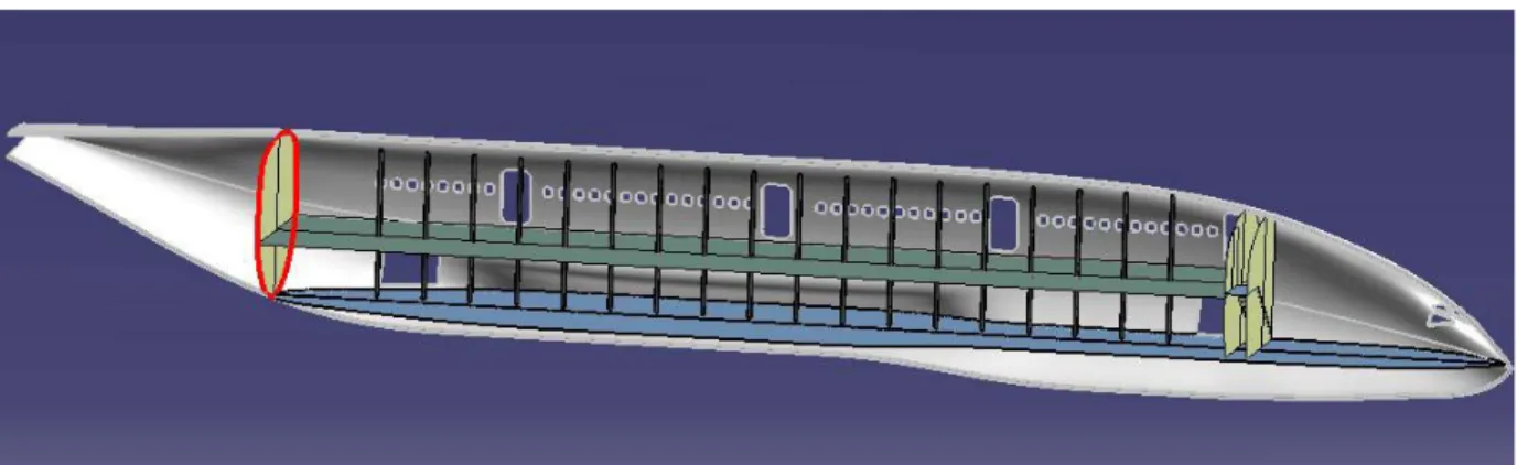
43 Figures 6. Lateral view and encumbrances
This section shape of the fuselage is optimum as far as load capability (passengers and cargo) and the main dimensions (in Figure 5 and 6) are 46.5 m long and 7 m large.
With such a fuselage section, the structural design becomes non conventional and experimental data are not available at the moment to optimize the structural weight. On view of a structural optimization the presence of struts is foreseen both in cargo the vane and in the passenger compartment (Figure.7).
Figure 7. Struts on symmetry plane
In the solution shown in Figure 6, a rear door is placed in the back fuselage.This door is very large and, hence, it could be not convenient for the structural efficiencyans safety as far as pressurizatio. Besides it could be difficoult to position the rear bulkhead.
PrandtlPlane Conceptual Design
Another possible configuration (Figure 8) would be obtained with a pressurization of both decks. In such a case the bulkhead must embrace even cargo deck and the cargo doors in the tail must be moved to the side of the fuselage. The containers are imbarked laterally, without any disadvantage; a second cargo door is positioned in the front fuselage
Figure 8. Back cargo door on the side of the fuselage
Figure 9. Perspectic details of the bulkhead position
Passengers Deck
Two classes were located on the deck in the following way:
PrandtlPlane Conceptual Design
45 - 210 in economy class, accommodated in the rear part of the aircraft.
The layout of the interior was made following the A.E.A. (Association of European Airlines) [5] regulations and is shown in the following figures. Two aisles have been adopted with a larger width than present aircraft.
Figure 10. Plan view of passenger deck
Figure 11-12. Seat’s dimensions of business (left) and economy class
Platforms, provided with service stations, have been foreseen in front of them (Figure 10). The sizes of the all doors are: height: 1.93 m and width: 1.07 m, so that they can be certified as emergency exits of class A (Figure 13 and 14, [8]);.
PrandtlPlane Conceptual Design
The window centres are positioned 1m above the deck level; the pitch between a window and the next one is estabilished into 500 mm [5].
Figure 13-14. Classification of emergency exits and their dimensions
The present safety requirements are fully satisfied; in particular, the locations and dimensions of the safety exits in order to permit an easy emergency evacuation a large space in front of any emergency exit has been provided.
Along the cabin the following services are located: - toilette: one for 30 passengers in business class;
one for 40 passengers in economy class. Area of every toilet ~1.2 m2 - galley: 0.05 m2
per passenger. - wardrobe: 0 ÷ 0.065 m2
per passenger.
These services are located in “islands” (as in the majority of the layouts currently adopted) as shown in following figures.
PrandtlPlane Conceptual Design
47 Figure 15. First island, for the business class.
Figure 16. Second island, for the economy class
TOILETTE TOILETTE GALLEY
PrandtlPlane Conceptual Design
Figure 17. Third island dimensions
Figure 18. Fourth island dimensions
The service area in the tail cone depends on the longitudinal position of the rear bulkhead, which corresponds to the rear longheron of the fin (figure 19).
In the present proposal, the available service area is so large that a more advanced position of the rear bulckhead is possible; even in this event the available space should be above the minimum request.
TOILETTE TOILETTE
PrandtlPlane Conceptual Design
49 Figure 19. Fifth island dimensions related to the position of bulkhead
Figure 20. Detail of liveability of business class
The front fuselage could be used in different ways. One is to provide a sitting room, equipped with proper windows. In the present context we show a simple utilisation as a service area, the passage to the pilot’s cockpit and the rest room (Figure 21.)
TOILETTE TOILETTE
GALLEY GALLEY
~ 3 m2 ~ 3 m
PrandtlPlane Conceptual Design
Figure 21. A possible solution for communicability between pilot’s room and passengers’ deck
The remaining space can be allocated for the board systems.
According to current regulations, the total number of crew members, pilots and flight assistants, is of 9 units, consisting of:
- 2 pilots - 7 flight assistants
A rest zone of about 19 m2, located behind the cockpit, is foreseen for the crew, as the main carrier companies indicate as desirable.
PrandtlPlane Conceptual Design
51 Figure 22. Resting room
PrandtlPlane Conceptual Design
Pilot’s cockpit
The cockpit was designed by taking into careful consideration the following aspects:
- The innovative and peculiar shape of the fuselage imposes to set the cockpit in a far advanced and, at the same time, lowered location, to comply with the requirements of visibility envelop shown in Figure 23 and, in a cleaner form, in figure 24, 25, 26.
PrandtlPlane Conceptual Design
53 Figure 25. Frontal angles of view envelopes
PrandtlPlane Conceptual Design
The location of the cockpit at the level of the passengers deck is not possible, because it makes it very difficult to satisfy the requirements set by the view envelope .
- Recent tragic terroristic events, have emphasized the importance of safety considerations, with the need of isolating completely the cockpit from the rest of the aircraft, for avoiding intrusions.
- The particular case of the fuselage considered, with the cockpit located below the passenger deck and accessible only to the crew, allows for a complete separation from the passengers deck.
Cargo deck
The front wing, due to the reduced thickness (nearly the half of a conventional aircraft) crosses the fuselage under the cargo deck; the fuselage is conveniently enlarged in this reagion (and usable for locating systems). The main landing gear is located laterally of the fuselage. Hence, the cargo compartment is as long as the complete aircraft, and the vertical gap between the two wings is maximized. The internal volume of the cargo compartement is 406 m2, and allows to embark 38 LD1 or 34 LD 3 containers.
The access to the cargo deck is possible through two doors in the tail section and two more in the front section as shown (Figures 27 and 28). The rear cargo doors, due to the before mentioned reasons, can be conveniently located in lateral position, as in figure 29.
Figure 27. Cargo doors
Anyway, in a freighter aircraft, without cabin pressurization, the solution in figure 27 can be applied as well.
PrandtlPlane Conceptual Design
55 Figure 28. Isometric view of cargo deck loaded with 32 LD3.
Figure 29. Cargo doors detail in case of cargo deck pressurized.
The position of the front cargo doors yields particularly critic the position of the leading edge of the front wing during loading and unloading operations. A further optimization design phase would lead to a new design of the rest room and to a different positions closely correlated to a good solution of the cargo doors (Figure 30 ).
The advantages of these solutions will be shown in the following section 3.2.3.
Main landing gears
The position and size of the main landing ghear depend on the position of the centre of gravity, on the aerodinamic performances of the aircraft at low speed, etc..
In the present activity, only preliminary assumptions are possible. The items of the main landing gear design are the followings:
PrandtlPlane Conceptual Design
Figure 30. Lateral cargo operations
a) the main landing gear is positionated at the fuselage sides in order to allows a continuous cargo compartement.
b) The solution adopted is modular, in the sense that it can be moved forward or backward in the fuselage without any modification of the main landing gear.
c) The main landing gear is positioned inside lateral sponsons to be optimized in the aerodynamical context. The solution shown in this thesis is indicative.
PrandtlPlane Conceptual Design
57
3.2.3 Comparisons in term of ergonomic aspects
The phase of preliminary design of the fuselage includes ergonomic considerations, with reference with two aircraft of the same design that is:
- Boeing 767-300 ER
- Airbus A330-200
The Boeing 767-300 ER is a twin engine aircraft (Figure 1) derived from the model 767-200, which became operational in 1986. It hosts 269 passengers in two classes, 24 in business class and 245 in economy class, housed on a surface of 184 m2 and in a volume of 484 m3. It can also embark 30 containers of type LD2 or 15 LD1 containers; the maximum fuel volume is 93 m3 [3] .
Figure 1. Boeing 767-300 ER
The Airbus A330-200 (Figure 2) originated from a joint project of aircraft A330-A340, is the first aircraft to be designed completely with the CAD technology. The A330-200 aircraft originated from the A330-300, the basic design of the twin engine versions of the project. It carries 253 passengers in three classes, 12 in first class, 36 in business class and 205 in economy class, housed on a deck of 225.24 m2 and in a volume of 337 m3. It can load up to 26 LD3 containers and the maximum capacity of the fuel tanks is 140 m3 [3].
PrandtlPlane Conceptual Design
Figure 2. Airbus A330-200
PrandtlPlane Conceptual Design
59 Figure 4. Containers LD2
Figure 5. Containers LD3
The following characteristics were taken into consideration for the comparison: • Comfort in the passengers deck;
• Loading capabilities of the cargo deck;
PrandtlPlane Conceptual Design
Passengers comfort
In order to quantify the comfort of the passengers and compare different aircraft, proper indexes needs to be defined,in particular,two indexes were considered as comparison; the ratio of the passengers number (PN) to the floor area (FA) and the ratio of the passengers deck volume (PDV) to the passengers number.
• Load index PN FA = passengers of Number area Floor . . . m2 • Comfort index PN PDV = passengers of Number volume deck Passenger . . . . m3
Data relative to the three aircraft are reported in Table 1, with reference to layouts hosting two passenger classes.
Table 1. Data for comparisons
The area of the passenger deck for A330-200 was obtained with CATIA® ,even though the
available data are not complete (Figure 6).
PP A 330 200 B 767 300
Passengers Number 258 293 [Ref.3] 269 [Ref.3] Floor Area 240 225 [computed] 184 [computed] Passengers Deck Volume 500 337 [computed] 484 [Ref.3]
PN PDV [m3] 1.4/1.6 1.15 1.79 PN FA [m2] 0.93 0.76 0.68
PrandtlPlane Conceptual Design
61 Figure 6. Determination of Floor Area of the A330 200
With reference to the parameter
PN FA
, the different capabilities of taking advantage of the potentialities offered by the surface of the passengers deck in the different cases, are emphasized.
Consequently it turns out to be impossible to make a realistic size comparison.
It becomes therefore necessary to make homogeneous the parameters for the comparison. Thus the number of passengers was computed, which would allow the PrandtlPlane to equal, in both cases, the load index of the competitive aircrafts.
It appears that the passenger accomodations for B 767 and A 330 are fixed. In the case of
PrandtlPlane the low density configuration is one of the possible accomodations.In order to
obtain the same
PN FA
coefficients other high density passenger configuration could be design in particular:
• 312 passengers to have the same value of the A 330 200 (54 more than in the proposed layout)
• 350 passengers for the B 767 300 ER (92 more than in the proposed layout)
PrandtlPlane Conceptual Design
Figure 6. Passengers’ deck of PrandtlPlane High Density (1), PrandtlPlane low density (2), B767 (3), A330 (4)
1 2
PrandtlPlane Conceptual Design
63 The new comfort indices becomes:
• passenger m PN PDV PP 3 6 . 1 = passenger m PN PDV A 3 330200 15 . 1 = • passenger m PN PDV PP 3 4 . 1 = passenger m PN PDV B 3 767300 79 . 1 =
The results obtained show a comfort index better than that of the A330 200 but lower than the
B767 300. This result displays once more the good ergonomic potentialities of the particular
shape of the fuselage.
The layout proposed has only an indicative value and it is far from an optimization of the volume available, which would require more detailed knowledge, of important factors like longitudinal position of bulkhead, position and volume of the cockpit for systems,etc.
The number of passengers can be increased in different ways as, for example:
- by reducing the very large space in front of the central exits, thus dropping the four emergency type A exits ;
- by reducing ( 12 cm ) the width of each aisle in the economy class. In this way it would be possible to set two additional seats in the central zone, provided one could reduce the diameters of the central struts;
- by reducing the width of each aisle in the business class. In this way it would be possible to set an additional seat in the central zone, provided one could reduce the diameters of the central.
- by utilising the wide surfaces usable in the stern and front areas with a more rational distribution of passengers and service platforms.
Considering the high flexibility of this project, two configurations has been provided:
Configuration 1
Changes done:
- reduction of corridors width in Economy class from 674 mm to 420 mm - reduction of corridors width in Business class from 715 mm to 480 mm - introduction of a couple of seats near the simmetry plane in Economy class.
- introduction of a line of seats in the central zone near the simmetry plane in Business class.