U
NIVERSITY OF
N
APLES
F
EDERICO
II
School of Polytechnic and Basic Sciences
DEPARTMENT OF CHEMICAL, MATERIALS AND INDUSTRIAL PRODUCTION
XXXI PHD PROGRAMME IN
INDUSTRIAL PRODUCTS AND PROCESSES ENGINEERING
CURRICULUM ON PRODUCTION TECHNOLOGY AND SYSTEMS
PHD PROGRAMME COORDINATOR: PROF. ING. GIUSEPPE MENSITIERI
Biaxial test on composite and polymeric
materials
PhD PROJECT SUPERVISOR PhD CANDIDATE
List of contents
List of Figures ... i
List of Tables ... iv
Abstract………..……….……….v
Chapter1.State of art………..……….………..1
1.1 Monoaxial and biaxial tests for characterization of materials….……….…1
1.2 Machine and devices for biaxial mechanical tests……….………..…3
1.2.1 Stand alone machine……….……….3
1.2.2 Test rig connected to pre-existing single-axis machines………..……..11
1.2.3 Test devices for composite and polymeric materials……….…..…….14
1.3 Shape for biaxial test specimen……….……….…………18
1.3.1 Shape for composite materials………..…18
1.3.2 Shape for polymeric materials……….…………26
References……….33
Chapter2.Study of a new equipment for biaxial tests………..……….35
2.1 Technical characteristics and components of the equipment………….……..……….35
2.1.1 Loading group……….………..36
2.1.2 The frame assembly……….………..40
2.2.3 Group for the transmission of motion……….…………41
2.2 Multibody analysis: MSC Adams………..………..43
2.2.1 Model construction in Adams………..43
2.2.2 Simulation results……….………..…53
2.2.3 Choice of bearings……….………..55
2.3 Creation of the model for finite element analysis……….…..…57
2.3.1 Linear static analysis……….………..62
References……….72
Chapter 3. Study of specimen shape for biaxial tests on composite and polymer materials……….73
3.1 Optimization of shape for composite materials……….……….73
3.2 Optimization of shape for polymeric materials……….……….81
References……….………85
Chapter 4. Experimental activity………..…86
4.1 Introduction………..………...86
4.2 Materials and method……….86
4.2.1 Materials………..………86
4.2.2 Test setup………88
4.2.3 Specimen preparation for DIC………..90
4.2.4 Biaxial tests and digital correlation of images………91
4.3 Results and fem validation……….93
4.4 Conclusions………..98
i List of figures
Figure 1.1 Biaxial testing machine for cruciform specimens (Makinde et al.)
Figure 1.2 Non-uniformity degree estimation of the strain within the useful length of three
cruciform specimens
Figure 1.3 Specimen shape of Boheler et al.
Figure 1.4 The isostress lines within the test section of the optimized specimen Figure 1.5 Horizontal test rig of Kuwabara et al.
Figure 1.6 σ-ε curve for a SPECEN steel (Kuwabara and Ikeda, 2002a, b)
Figure 1.7 Relationship between load and strain during uniaxial and biaxial tests.
(Shimamoto et al., 2003)
Figure 1.8 Failure of the specimen after the biaxial dynamic test (Shimamoto et al., 2003) Figure 1.9 σ-ε curve in uniaxial and biaxial test (Shimamoto et al., 2003)
Figure 1.10 σ-ε curve for high-strength steel Figure 1.11 Test rig (Fraunhofer, 2005)
Figure 1.12 Pantograph mechanism for the biaxial test (Ferron and Makinde, 1988) Figure 1.13 Equipment for the biaxial test (Smits et al. 2006)
Figure 1.14 Types of Arcan systems: (a) classic type, (b) modified type Figure 1.15 Photographs of the Arcan plant and instrumental assembly Figure 1.16 Biaxial test machine (Brieu et al.)
Figure 1.17 Cross-shaped specimen with a circular and reduced central section Figure 1.18 Cruciform specimen with notches
Figure 1.19 Schematic drawing of a specimen for biaxial tests used by Welsh et al.
Figure 1.20 Schematic drawing of a modified specimen for biaxial tests used by Welsh et
al.
Figure 1.21 Detail of the round and square measuring section for a cross-shaped specimen
with a tapered thickness
Figure 1.22 Strain along the main direction in the four cruciform geometries [11] Figure 1.23 Shear strains in the four cruciform geometries[11]
Figure 1.24 Types of specimens for the biaxial tests of Arnaud. 3D CAD model and
axisymmetric 2D model: (a) straight edge, (b) cleaned edge, (c) pecking with a cleaned edge, (d) chamfered edge with polished edge, (e) bevelling with a cleaned edge and pecking
Figure 1.25 Typologies A, B and C of specimens analyzed by Chwdhury
Figure 1.26 Comparison between numerical results and experimental observations of
Zarouchas and Nijssen
Figure 1.27 Schematic diagram of a biaxial specimen according to Duncan. The dotted part
shows how the corners have been removed for some analysis
Figure 1.28 Specimen dimensions of Brieu et al. Figure 1.29 Hollenstein et al. specimen
Figure 1.30 Boundary conditions of Hollenstein specimen Figure 1.31 Test machine and specimen of Smidt et al. [18] Figure 2.1 New equipment
Figure 2.2 Clamps properties
Figure 2.3 CAD modelHydraulic Wedge Grip MTS 647
Figure 2.4 CAD model of connection between Hydraulic Wedge Grip MTS 647, spiral
washers and relative slider
Figure 2.5 CAD model SPIRAL WASHERS model 601 Figure 2.6 CAD model of the slider
Figure 2.7 CAD model of box
ii
Figure 2.9 CAD model of a crank
Figure 2.10 CAD model of a connecting rod Figure 2.11 Units settings in Adams
Figure 2.12 File import setting Figure 2.13 Part name setting
Figure 2.14 Detail of slider with clamp imported into Adams Figure 2.14 Setting of the material characteristics
Figure 2.15 Complete model in Adams Figure 2.16 Degrees of freedom
Figure 2.17 “Fixed” constraint assignment
Figure 2.18 Assignment of fixed constraint to the box Figure 2.19 Revolute constraint between crank and axle
Figure 2.20 Spherical constraint between cranks and connecting rods Figure 2.21 Hooke constraint
Figure 2.22 Translational constraint between slider and box Figure 2.23 Motion constraint assignment
Figure 2.24 Motion constraint assignment of parameters Figure 2.25 Force assignment
Figure 2.26 Model check
Figure 2.27 Time and step integration parameters Figure 2.28 Displacement law of sliders
Figure 2.29 Forces between cranks and axles
Figure 2.30 Forces between cranks and connecting rods Figure 2.31 Bearing data sheet
Figure 2.32 New model assignment
Figure 2.33 Surfaces for the creation of connecting rod model Figure 2.34 Mesh of connecting rod
Figure 2.35 Complete mesh of the connecting rod Figure 2.36 RBE2 constraints
Figure 2.37 Material parameters Figure 2.38 Slider fem model
Figure 2.39 Support structure fem model Figure 2.40 V-shaped crank fem model Figure 2.41 Box fem model
Figure 2.42 Connecting rod strains Figure 2.43 Connecting rod stresses Figure 2.44 Crank strains
Figure 2.45 Crank stresses Figure 2.46 Slider strains Figure 2.47 Slider stresses Figure 2.48 Support arm strains Figure 2.49 Support arm stresses Figure 2.50 Axle strains
Figure 2.51 Axle stresses
Figure 2.52 Box strains in case of thickness 50 mm Figure 2.53 Box strains in case of thickness 80 mm Figure 2.54 Box stresses in case of thickness 80 mm Figure 2.55 Rationale behind the deformability analysis Figure 2.56 Importation of a flex component in Adams Figure 2.57 Setting of flex component properties
iii
Figure 2.58 Detail of flexible cranks
Figure 2.59 Equipment with all flexible components during the analysis
Figure 2.60 Comparison of the law of motions in both cases: rigid and flexible components Figure 3.1 Stacking sequence
Figure 3.2 Investigated shapes
Figure 3.3 Guelho et al. specimen shape and dimensions [2] Figure 3.4 Modified shape
Figure 3.5 Solid shell element [3] Figure 3.6 Solid shell mesh Figure 3.7 Boundary conditions
Figure 3.8 Deformed of the fem model
Figure 3.9 Main strains a) I and b) II for layer1; main strains c) I and d) II for the layer2 Figure 3.10 Stresses in the direction a) x and b) y in the CSYS11 reference system for
Layer1; Stresses in direction c) x and d) y in the CSYS11 reference system for Layer2
Figure 3.11 2D shell mesh
Figure 3.12 Boundary conditions and loads Figure 3.13 Von Mises strains
Figure 3.14 New shape proposed for polymeric materials Figure 3.15 Chexa element
Figure 3.16 Main stresses on Versilok specimen Figure 3.17 Main stresses on Sikasil specimen Figure 4.1 Fibre Data Sheet
Figure 4.2 σ-ε curve
Figure 4.3 CAD model of definitive equipment Figure 4.4 New equipment for biaxial tests Figure 4.5 Details of cranks and clamps Figure 4.6 Speckle pattern on specimen
Figure 4.7 Detail of speckle pattern in the biaxial zone Figure 4.8 Camera positioning
Figure 4.9 Biaxial test performing Figure 4.10 Image calibration Figure 4.11 Area of interest Figure 4.12 DIC analysis settings
Figure 4.13 Distribution of maximum strain in the main direction with DIC Figure 4.14 Distribution of maximum strain in the main direction with fem Figure 4.15 Values for identified element on Patran model
Figure 4.16 Maximum strain distribution in the main direction Figure 4.17 Strain in y direction
Figure 4.18 Strain in x direction Figure 4.19 Slider inclination Figure 4.20 Flexion of the arms Figure 4.21 Detail of cranks
Figure 4.22 Areas of possible crank contact Figure 4.23 Position of the springs
iv List of tables
Table 2.1 Grip specifications Table 2.2 Possible constraints
Table 2.3 Mechanical properties of 39NiCrMo3
Table 2.4 Comparison between rigid and flex analysis results Table 4.5 Comparison between DIC and fem values
v Abstract
The development of the aircraft with the use of composite materials involves the mechanical characterization of these materials that have the suitable properties to be used in the design phases. The characterization of these materials is made in the mono axial field. However, research activities in recent years are focusing the attention on the study of biaxial tests to get more information to use during the design for the best use of materials.
My thesis has been mainly focused on the development of a new biaxial equipment about composite and polymeric materials. It will try to show that the equipment is able to correctly load the specimens in two perpendicular directions. Then the selected test setup was applied experimentally for biaxial tests on a general aviation carbon resin. The thesis is divided into four sections.
In the first one, the machines and equipment for biaxial tests present in the literature are only presented. Then the forms of biaxial test specimens most used by researchers in the last years for both metallic, composite and polymeric materials have been described. In the second section, the agreement that led to the creation of a new test rig, with which the tests have been described, are in the fourth section. The third part deals with the choice and optimization of a specimen shape through the use of finite element analysis. In the fourth section, the new equipment and the shape of the specimen chosen in the previous section have been used to carry out tests on a composite material in carbon resin. Here, the materials and the methods used to perform the experimental exercise are described.
The used material is provided within the Tabasco
project promoted by the Campania DAC. This project concerns the technologies and the production processes of low-cost components for general aviation.
Chapter1 STATE OF ART
- 1 -
Chapter 1
State of art
1.1 Monoaxial and biaxial tests for characterization of materials
When we select a material to make a component of a structure, a machine or any product, the main objective is to ensure that its properties are suitable for the operating conditions of the component.
Through the evaluation of physical and mechanical properties, it is possible to distinguish different types of materials.
Among the properties that characterize a material, it can be found: density, melting point, optical properties, thermal conductivity, electrical conductivity, and magnetic properties.
Some of these could be of primary importance, but very often the properties that describe how a material reacts when led, have a fundamental role in the choice of the same.
In particular, these are: the elastic modulus, the ductility, the hardness.
The mechanical properties are very important because the function and the performance of a product depend on its ability to withstand the stresses that it must face during this operation.
When the selection of the material is required, the engineer must not only look at its properties but also understand what values and limits are relevant. Mostly, how they are measured.
For these reasons, the engineer must have familiarity with the different procedures used during the tests on materials, and, at the same time, it must consider that the mechanical tests are carried out on specimens. But, these, although, the laboratory conditions are respected, rarely, correspond to the real life application.
When the load is applied to a component, the material deforms, and, in particular, it can be subject to three types of load: traction, compression and cutting.
Chapter1 STATE OF ART
- 2 -
while the cutting causes the sliding of the surfaces.
These three types of loads are described through the stress-strain curves. The most used in mechanical tests are the monoaxial ones.
The mechanical properties of materials under single-axle loading are used to estimate the strength and the strain of components during the design of a machine, a structure or a product.
Knowing that loads only act in one direction, it is a simplification that is acceptable for analysing a single point or common materials, like metals.
It must be remembered that during the operation, the conditions the loads are applied simultaneously in different directions, produce a stress that is not directed in a particular direction.
For example, during the operation, the mechanical components obtained by forming, are loaded in different directions at the same time, and, in particular, they are loaded into two axes.
Many aeronautic and aerospace components are also often subject to multi-axial loads.
In general, multiaxial stresses and strains in components that work at high temperatures cannot be described by monoaxial data.
It has been recognized that evaluating the characteristics of a material through a monoaxial test, we can have a wrong evaluation of the material behaviour.
The monoaxial tensile test is used to classify the workability of several metallic alloys.
However, the actual strain of the breaking zone, observed in the monoaxial case, is much lower than the corresponding value found in the biaxial case. For this reason, into the monoaxial tensile test, the deformability, during the real training process, can be underestimated.
By using more realistic loads, and, in particular, introducing biaxial loading conditions, a more accurate representation of the operating behaviour of a structure is obtained.
In general, the stresses acting on a component are multiaxial. For the mentioned reasons, it is necessary to identify the mechanical properties not only under
Chapter1 STATE OF ART
- 3 -
monoaxial load states but also under multiaxial ones.
Nowadays, the tests are designed in order to reproduce forces that strongly reflect those that act on the material during the training process with specific instructions.
Biaxial tensile tests can be used to simulate forces acting in two directions at the same time. Thanks to this type of test, the σ-ε curves can be obtained from different load directions. There are numerous methods to produce a biaxial stress state in the material made up of many types of specimens: for example, the test with combined torsion-stress. The first one with flexion and flat stress and the swelling test [1].
Furthermore, the ever-increasing use of polymeric materials, fiber-reinforced composites and metal laminates have underlined the importance of carrying out tests through multiaxial loading conditions, unless they are biaxially or multiaxially stressed during the operation.
Biaxial tests, ready to use different types of cruciform specimens, represent the most suitable method to evaluate several biaxial stress conditions by reversing the value of the load or displacement along the two axes.
Furthermore, the single-axis standard test is accurate only for isotropic materials, while thin sheets, composite materials and polymeric materials show anisotropic properties.
1.2 Machine and devices for biaxial mechanical tests
To perform biaxial mechanical tests in order to characterize composite and polymeric materials, machines and devices have been developed to be able to reproduce multiaxial loads.
In particular, they have some features: • "Stand alone" biaxial test machines
• Test rig that connects to pre-existing single-axis machines to produce biaxial loads.
1.2.1 Stand alone machines
An example about this topic is the biaxial testing machine designed by Makinde et al. (1992) shown in figure 2.1. The device consists of two main parts: the loading system and the control system. The loading system is
Chapter1 STATE OF ART
- 4 -
configured as shown in the figure. The frame has been oversized to reduce strains, as it is subject to great stress. On the chassis, along with the two axles, two hydraulic actuators have been constructed with a nominal capacity of 250 kN. The presence of the actuators on both axes ensures that the centre of the specimen does not move during the test, anyway, they are constructed in opposite ways and connected to the same hydraulic circuit to reproduce equal and opposite forces.
Figure 1.1 Biaxial testing machine for cruciform specimens (Makinde et al.)
The load cells constructed on each actuator are used to measure the force in both directions. Once grabs have been designed, they can be preloaded and can block the specimen before the start of the test. This machine was used to test many types of cruciform specimens. The results of these tests were used to develop a specific specimen for low strains [3].
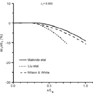
The researchers used the machine to evaluate the degree of non-uniformity of the strain within the useful part of different cruciform specimens proposed by other researchers as shown in figure 2.2.
Chapter1 STATE OF ART
- 5 -
Figure 1.2 Non-uniformity degree estimation of the strain within the useful length of three cruciform specimens
Another type of biaxial machine was made by Boehler et al. (1994).It was composed of four double action screw-driven pistons constructed on an octagonal vertical frame. The four double action pistons assured the locking of the specimen centre during the tests; the screws were activated by two engines. For the tests, a variable DC motor was used, while for the initial positioning an AC motor was used for large displacements. Both engines had a clutch to prevent simultaneous joints. The speedy test could be varied between 0.003 and 0.3 [mm / min]. The maximum load that could be reached is 100 [kN] in both directions. The advantage of using a vertical frame is to have easy access from both sides to construct the specimen, and, it is, also, possible to have a good photographic analysis to analyze the strain field with the laser or other video methods.
This configuration, however, involves a disadvantage. In fact, the weight of each pincer and of the assembly devices must be kept under control to minimize bending on thin specimens.
This machine was used to test a lot of types of cruciform specimens in order to develop an optimal shape of the specimen.
Chapter1 STATE OF ART
- 6 -
Figure 1.3 Specimen shape of Boheler et al.
The form of the specimen considered by Boheler et al is shown in Fig. 1.3. Researchers used the analysis of finite elements to optimize and comparing the specimen with previously designed specimens. Both rigid grippers and the axes were calibrated on the specimen optimized for an anisotropic elastic material. The numerical model was used to detect the field of shear stresses in the useful area of the specimen. An example of the isostress lines within the test section of the optimized specimen is shown in figure 1.4.
Figure 1.4 The isostress lines within the test section of the optimized specimen
The value at the centre of the section is σxy ≈5.8 [MPa].
For this reason, it was concluded that when the test was focused on anisotropic materials with rigid clamps, the information obtained could not be used to derive the constitutive bond because the main axes of the biaxial stress field obtained could not be determined.
Kuwabara et al (1998) completed a study to clarify the behaviour of elastic and plastic strain of a low-carbon cold-rolled steel under biaxial load.
Chapter1 STATE OF ART
- 7 -
To complete this experiment a new device for biaxial tests was built. The configuration of this servomechanism is shown in figure 1.5.
Figure 1.5 Horizontal test rig of Kuwabara et al.
The opposing hydraulic cylinders were connected to a single hydraulic circuit in a way that the same pressure was applied to both. Each hydraulic circuit was controlled independently using a server control. As for the two previous devices, it was essential to keep the centre of the specimen locked during the test. This was achieved using a type of articulated pantograph like the one shown in figure 1.5.
This method was very effective and reduced, with relevance, the costs of the apparatus. In each direction, a load cell was used to calculate the load acting on the specimen. The strain was measured using a strain gauges, which was positioned at the specified section of the specimen. The output of both cells and the strain gauges were analyzed using a calculator. This device was used to test a cruciform specimen of very low carbon steel (SPECEN) and, then, to compare the results obtained with other existing yield criteria as shown in fig. 1.6 (Kuwabara and Ikeda, 2002 a, b).
Chapter1 STATE OF ART
- 8 -
Figure 1.6 σ-ε curve for a SPECEN steel (Kuwabara and Ikeda, 2002a, b)
It was observed that the curve detected corresponded to the Hosford yield criterion.
Shimamoto et al. in 2003 developed and validated a bench device for the realization of lots of types of biaxial tests. This device had the ability to perform both static and dynamic tests at controlled temperatures. This biaxial machine presented a vertical configuration.
The applied load was measured with a load cell in each direction and strain gauges were used to measure the strain. Hydraulic actuators were used to perform the test, which meant that the hydraulic circuit included both a static and a dynamic part. The hydraulic actuators were used to provide both the pressure for static tests and that pressure for dynamic tests. A programmed controller was used to monitor the circuit. This device had characteristics that exceeded the limits of the previous devices: a) The test device had a vertical configuration. The developed biaxial machine consisted of 4 actuators, which were oriented at 90 °. The four cylinders operated independently and the centre of gravity was always held in its initial position. (b) Different types of tests, uniaxial traction and compression tests, biaxial traction and compression tests, static and dynamic, biaxial tests under the same biaxial load of bars or plates, changing only the type of grip. (c) It was possible to compare tests under different loads (load ratios from 1: 1 to 1:4) biaxial, static and dynamic under combined loads, biaxial dynamics cutting tests and other load combinations. In addition, the machine was equipped with a cooling liquid (Argon) and an electric heating system, which allowed to perform the dynamic test at a controlled temperature. With this machine, different aluminium specimens were tested at the rate of 0.02 [mm / s] for each axis.
Chapter1 STATE OF ART
- 9 -
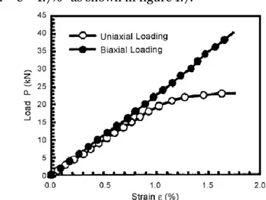
It was confirmed that there was a relationship of proportionality between load and strain “ ε = 1.7%” as shown in figure 1.7.
Figure 1.7 Relationship between load and strain during uniaxial and biaxial tests. (Shimamoto et al., 2003).
Shimamoto et al. also used the device to perform dynamic tests useful for studying the propagation of a crack.
In particular, a cruciform aluminium alloy test took place (A7075-T6) at a speed of 1000 [mm / s]. It contained a 30 [mm] long crack put at 45° from the centre. The failure of the above specimen after the biaxial dynamic test is shown in fig. 1.8.
Figure 1.8 Failure of the specimen after the biaxial dynamic test (Shimamoto et al., 2003)
It is evident that the crack propagation has a bilateral symmetry.
The researchers concluded that the device was suitable for both monoaxial and biaxial tests. Test specimen broke after the dynamic biaxial test (Shimamoto et al., 2003).
Another machine was designed by Gozzi et al. to study the behaviour of a high-strength steel under biaxial load. It consisted of two actuators constructed
Chapter1 STATE OF ART
- 10 -
perpendicularly to each other and four arms hinged to the lower end of the device. The two actuators were self-aligning, while the main disadvantage, deriving from the use of articulated arms, was that the grippers moved along an arched profile. The actuators were controlled by an Instron control unit that could control two actuators independently.
All tests were examined under load control, with a nominal load of 2.7 [MPa / s].
The results from the monoaxial and the biaxial tests were compared, as shown in figure 1.9.
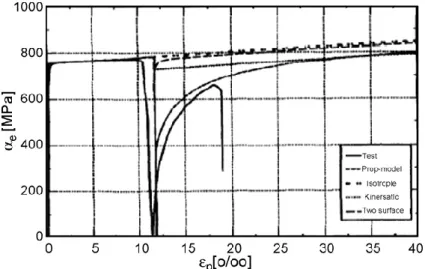
Figure 1.9 σ-ε curve in uniaxial and biaxial test (Shimamoto et al., 2003)
From figure 1.9 it can be concluded that the stress in the biaxial specimen during the initial stress can be determined by an accurate monoaxial test. Granlund studied the effect of a bending force on a cruciform specimen during a biaxial test and found that when a bending force was introduced, it was very small and could also be neglected.(Granlund, 1995, Granlund and Olsson, 1998). These researchers also designed a lateral support plate to prevent buckling during compression tests. The support plates were clamped around the specimen and the clamping force was measured to keep friction losses under control. Furthermore, particular attention was paid to the design of a cross-shaped specimen that allowed the stress in the specific area determined by the external load. Two different grades of steel were tested, one with high and yield strength of 690 [MPa] and one structural mild steel with a yield strength of 275 [MPa].
Chapter1 STATE OF ART
- 11 -
Mises and that of Tresca corresponded to previous observations. The following yield criterion was characterized by the Bauschinger effect and a more gradual transition into plastic . So, a new constitutive model was proposed; as shown in figure 1.10, which took into the gradual change under loading conditions [1].
Figure 1.10 σ-ε curve for high-strength steel
1.2.2 Test rig connected to pre-existing single-axis machines
In order to reduce the costs of manufacturing stand-alone test machines, an alternative way to run double-axes tests is the use of auxiliary devices designed for existing machines used for tensile and compressive tests.
Usually, to perform a biaxial test, the operation consists in the conversion into a standard machine for traction. This is achieved by adding a further actuator to the pre-existing system. For example, an horizontal piston can be connected to the vertical traction machine. The existing machine is used to apply the load in the vertical direction, while the removable mechanism is used to put on the load in the horizontal direction. The device was designed by Hoferline et al (2000). It consisted of a removable hydraulic actuator linked to a standard traction machine.
Both horizontal and vertical directions had a load cell and an alignment device. The horizontal device was constructed on a low-friction bearing to ensure that the horizontal structure stayed aligned to the centre of the specimen during the test.
Another biaxial device test was developed at the Fraunhofer Institute in Germany, converting in a compressing machine, through a series of links. (Fraunhofer, 2005). This device is shown in figure 1.11.
Chapter1 STATE OF ART
- 12 -
Figure 1.11 Test rig (Fraunhofer, 2005)
As we can see from the above figure, the operation of this system is based on the use of four elements added to the load across the compressing machine. When the loading element of the machine moves downwards, the four rods convert the vertical movement into a bidirectional horizontal movement. This movement was used to apply the biaxial force into the cruciform specimen.
As in the cases previously seen, a load cell was used in each direction to measure the applied force, while a camera was used to detect the lengthening of the specimen.
Mohr and Mulalo (2004) used a test on the compressing machine to verify the honeycomb structure under a multi-axial load.
This universal testing device (UBTD) was employed to join large compression displacements combined with those of shear at the edges of the specimen. A further approach to transform a tensile testing machine into a biaxial testing machine is the method that exploits connecting parts. It was studied and developed by Ferron and Makinde (1998). Through the use of eight parts connected to each other, there was the possibility to convert the vertical movement of the machine crosshead into a bidirectional movement of the grippers. This mechanism is shown in figure 1.12.
Chapter1 STATE OF ART
- 13 -
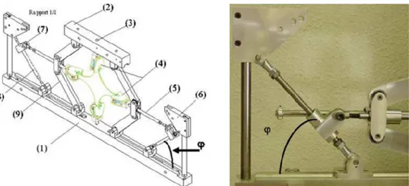
Figure 1.12 Pantograph mechanism for the biaxial test (Ferron and Makinde, 1988)
After constructing the specimen on the device, the complete system is linked up to the testing machine through the head crosspieces H1 and H2, through which the specimen is stressed. During the test, the displacement of the vertical frame, consisting of four arms Av, has ensured a decrease in terms of distance between the connected elements C1 and C2, which have produced an adequate displacement of the horizontal frame made by the four arms Ah. For this reason, there is a greater distance between the two heads H3 and H4. Studying this configuration, we can say that this distance between H3 and H4 was equal than the distance between H1 and H2. The specimen, connected to the four heads H1, H2, H3 and H4, was subject to an equi-biaxial strain through the main connecting plates. When a tensile load was applied to the two heads H1 and H2, the vertical arms were subject to a tensile load whereas the horizontal ones were subject to a compressing load. It can be said that the balance of the specimen strain is true if the elastic strain of the mechanism is negligible. The load on the specimen was measured by two load cells, which were positioned on the H1 and H4 heads.
This mechanism was also used by Terriault et al (2003) to test different alloys at different degrees of temperature. The main difference with this apparatus was that the device used a compressing machine. Here, a compressing force was applied to head C1 and C2, which applied the same movement to the grips as in the previous configuration. The pantograph apparatus converted a
Chapter1 STATE OF ART
- 14 -
compressing load applied to two cruciform membranes into a biaxial traction across eight articulated arms. The strain was measured using a video extensometer. In this process of study, the aim was to examine whether the beginning of the transformation could be described by the Von Mises’ criterion. To achieve this, a test was performed on a Ti-Ni alloy at different degrees of temperature. During the experiment at high temperatures, it was observed that the thickness of a portion of the specimen caused the breakage outside the section. Subsequently, the minimal plastic strain was observed in the section of the specimen which resulted an incomplete stress-strain curve. Makinde et al. (1992b) developed a biaxial strain gauge to measure the strain in the cruciform specimen. The strain gauge allowed both control and strain measurement along two orthogonal directions. The measure of strain in one direction was completely independent from the others. Tests were carried out using the strain gauge on metal sheets and it was delivered to be an excellent method to measure medium-low strains [1].
1.2.3 Test devices for composite and polymeric materials
Unlike metals, only recently, scholars have begun to understand the breakdown of composites under multi-axial loads.
Because of the anisotropic structure of the material, the resistance under biaxial load strongly depends on the direction of the fibers of the material during the test, addressed to the conduct of the load. If the load and the fibers are correctly oriented, the biaxial strength can exceed the value that could be found by a simple uniaxial tensile or compressing test. Otherwise, the resistance can be even much lower. Some researchers believe that the only way to overcome many of these problems is to carry out long-term studies aimed to confirm numerical results through reliable experimental information.
Among these, the biaxial tests, which allow to have results in the space σ1-σ2 and give essential design parameters for the breakdown of the composites, are the most difficult and expensive to realize.
To produce a biaxial stress state, several experimental techniques and types of specimens were used.
These techniques can be classified into two categories: (i) Tests using a single loading system
Chapter1 STATE OF ART
- 15 -
(ii) Tests using two or more independent loading systems.
In the first category, the value of the biaxial stress depends on the geometry of the specimen or on the configuration of the loading device, instead of, in the second category it depends on the value of the applied load.
An example of the tests belonging to the first category are the bending tests on cantilever beams and tests using special devices.
Especially, for composites, single-axis specimen tests that have fibers oriented on different axes produce a complex state of stress in the material reference system, also consisting of two or three components in the stress tensor plane.
The respective stress values, however, depends on the angle of orientation of the fibers.
Examples of the second category are a torsion-twisted round bar, thin-walled tubes subjected to a combination of tensile / compression and torsion or internal/external pressure and cruciform specimens under planar biaxial loads.
The most realistic technique, then, is to create a biaxial stress state by applying loads in the same plane along the two arms of a cruciform specimen. Nowadays, it is trying to establish a procedure for biaxial tests and to develop an accurate failure criterion.
The biaxial planar test device by Smits et al. (2006), as shown in fig. 1.13, is a machine that uses four independent hydraulic servo actuators with a special control unit and load cells. This is a very expensive equipment.
Figure 1.13 Equipment for the biaxial test (Smits et al. 2006)
The use of polymeric adhesives like a replacement to traditional riveted structures allows the construction of joints in which there are great
Chapter1 STATE OF ART
- 16 -
advantages compared to mechanical clamping. In fact, they allow the development of larger structures and more uniform load distributions, unless the gluing area is larger. In addition, the glued structures are more rigid, given the continuity of the gluing itself, and do not show variations on the surface and on the structure of the combined materials. So, the need arises to perform biaxial characterizations also on this type of material.
The types of adhesives can be divided into two categories: • Structural adhesives
• Flexible adhesives
The former has an elastic behaviour up to break with low strain volumes. The latter is characterized by a high breaking strain and low elastic modules. Structural adhesives are used to make rigid joints. The base material is generally a resin with a fairly high modulus of elasticity (3-4 GPa). The material, thanks to its cure process at particular temperatures, creates chemical bonds between molecules, generating a high density and therefore a high rigidity.
Very often the structural adhesives are made by adding to the base resin rubber particles that allow to increase their stiffness and consequently the amount of strain before breaking.
The behaviour of structural adhesives with low strains can be modelled through a linear elastic function that in FEM software is extremely simple to implement as a material of this kind. It is completely described by an elastic modulus and Poisson coefficient, obtained through experimental methods, such as, by tensile test.
In 2004 Cognard, Davies et al. [5] developed a system useful to study the behaviour of an adhesive joint subject to tensile and compressive stresses combined with shear stresses. The study started with a machine developed by Arcan in 1987 to understand the fracture behaviour of composite materials. Cognard and al. hypothesized that, with the appropriate modifications, the machine was ideal to generate a load in several directions aimed at the study of adhesives.
Chapter1 STATE OF ART
- 17 -
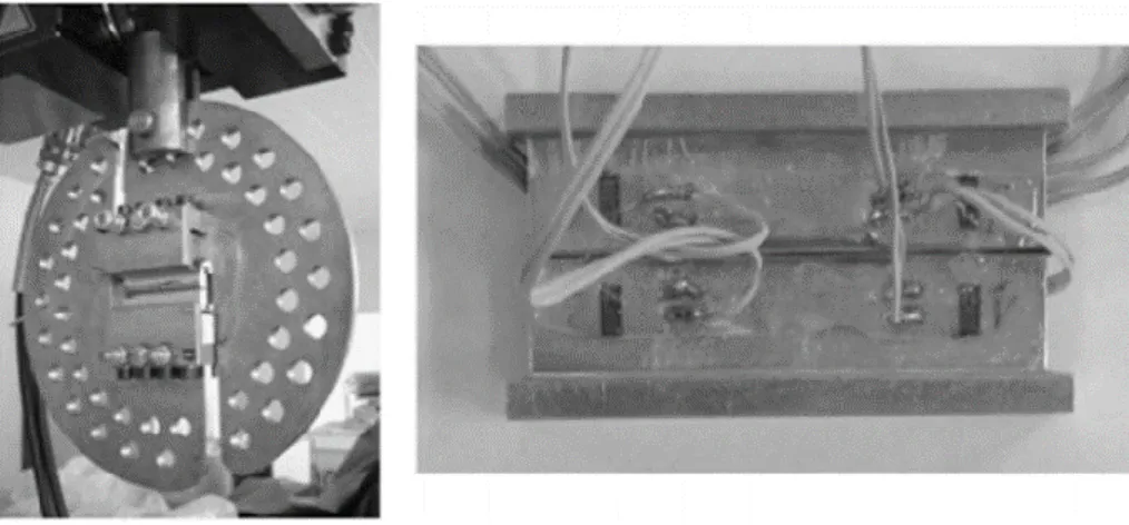
Figure 1.14 Types of Arcan systems: (a) classic type, (b) modified type
Figure 1.15 Photographs of the Arcan plant and instrumental assembly
For hyperelastic materials, such as adhesives and rubbers, the biaxial load test is performed in order to validate the analytical model used to represent the behaviour of the material.
In the literature, there are a lot of examples of biaxial testing systems or conversion of monoaxial traction machines in biaxial machines to perform tests on hyperelastic materials and composite materials
In general, these machines are classified into two large families: • Separate Load
• Single load
The systems that provide as many load cells as the actuators are available in the first family and are all independently manageable. These machines can be used to reproduce different multi-axial tension states with extreme precision, with the disadvantage that investment costs are very high.
Chapter1 STATE OF ART
- 18 -
The second family includes the machines and conversion systems of a single-axis test machine that use only one actuator and only one load cell. The cost of such device is lower than that with multiple load cells. Moreover, a machine of this kind can also be used for single-axis tests.
Brieu, Diani and Bhatnagar in 2007 [12] proposed a new type of machine capable of producing equi-biaxial and non-equibiaxial stresses on each plane of the specimen.
Figure 1.16 Biaxial test machine (Brieu et al.)
The system has been designed to perform cyclic biaxial stress tests with wide strains, with an elongation in the two tension directions and with different load ratio values. The authors Brieu, Diani and Bhatnagar have demonstrated, through their new test machine, that the unit of measure will not be a pure biaxial measurement, but the result of a biaxial traction with an "r" ratio between the variable elongations during the test.
1.3 Types of shape specimen for biaxial test
1.3.1 Shape for composite materials
The characterization of composite materials subjected to uniaxial loads is not able to evaluate the actual behaviour of an engineering component. In fact, many structural components are subject to multiaxial loads [4].
Chapter1 STATE OF ART
- 19 -
Therefore, biaxial and multiaxial tests were made to perfect the mechanical behaviour of these complex materials, necessarily. Recent years many different set-up tests have been used to produce biaxial stress state, for example, cruciform specimens under in-plane biaxial loading; torsion and internal/external pressure; bending tests on rhomboidal composite plates and tubes subject to a combination of axial loading. Although in theory these tests should have given an advance of composite knowledge, practically, they did not give reliable results [5].
In particular, in the field of composite materials different shapes of cruciform specimens subject to biaxial load were studied with FEM. analysis and tested, but not successfully completed according to the following requirements:
- maximisation of the region of strain uniformity into the biaxial loaded zone;
- minimization of the global shear strains in the biaxial loaded test zone; - minimization of the strain concentration/failure outside the test zone of interest;
- specimen failure in the biaxial loaded test zone; - repeatable results. [4-8].
In 1992 Makinde, Thibodeau and Neale [2], referring to the previous studies by Monch et al. [9] have begun to lay the groundwork for carrying out biaxial tests on carbon resin laminated, as precisely as possible. The study dealt with the search for a better geometry that allowed the birth of a larger biaxial stress state in the centre of the specimen. There are two different geometries to consider thanks to their study:
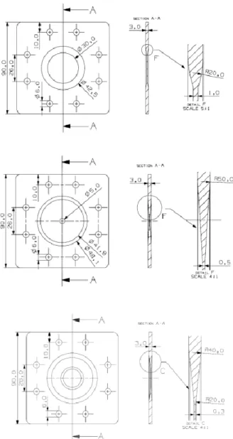
1) specimens for tests subject to small strains which have a circular section in the centre where the thickness is reduced (fig. 1.17)
2) specimens for large strains that have a central rectangular section with notches in the arms (fig. 1.18)
Chapter1 STATE OF ART
- 20 -
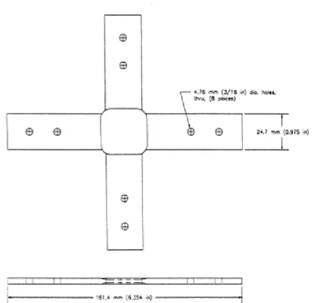
Figure 1.17 Cross-shaped specimen with a circular and reduced central section
Figure 1.18 Cruciform specimen with notches
From a study by Monch of 1963 [9] it was understood that removing the disturbances produced by the lateral stress of the edges of the specimen it was necessary to insert the notches on the arms of the same. Moreover, it was possible, thanks to them, to produce any two-dimensional load by moving the biaxially specimen.
The notches also allow reducing the rigidity of the arms which could reduce the maximum strains obtained at the centre of the specimen and also restricting the homogeneous stress region.
Chapter1 STATE OF ART
- 21 -
there is the concentration of the stress between the arms and the central section, in the transition zones, as well as, the concentration of stress in the notches near the measurement area that leads to premature breaking of the specimen.
As we have seen, there are several geometric parameters that cause the variation of the results from test to test. Makinde et all. they have studied a series of geometric variables that influence the distribution of stress and strain.
A specimen used for low strains has seven geometric variables that most influence the test:
1) Width of the arms (2Wa)
2) Length of the specimen outside the grips (2L) 3) Connecting radius between the arms (Rf) 4) Radius of the circular measuring region (Rc) 5) Passing radius (Rt)
6) Arm thickness (Ta)
7) Ratio between the thickness of the arm and that of the measuring section (Ta / Tg)
For a specimen used for large strains, with the notches, there are five other variables to consider:
8) Width of the central section (2Wc) 9) Diameter of the carvings (Dslot) 10) Number of carvings (Nslot) 11) Length of the carvings (Lslot) 12) Location of the carvings (Xslot).
The problem is how to determine an optimal combination of the variables to obtain the desired results, as a uniform distribution of stresses and strains for both geometries. The traditional method of changing one variable on time could not work because of the interactions between two or more of them. Makinde has decided to adopt a design on a statistical basis able to combine the change of several variables. For each combination, the measured effects were the width of the measurement area, where stress and strain did not have to be moved more than 5% away from the central values of the specimen, nor that maximum elongation obtained in the centre of the specimen before breaking.
Chapter1 STATE OF ART
- 22 -
forms of specimens (fig.1.19), focused the attention on the improvement of the same (especially about the measurement area that is made with a smaller thickness) , they carried out tests on a laminate AS4 / 3501- 6 cross-ply carbon/epoxy.
Figure 1.19 Schematic drawing of a specimen for biaxial tests used by Welsh et al.
The first improvement consisted of removing the internal hole, to align the specimen with the grips, from each arm. This is because the position near the edge of the arm is the one with the lowest stress and therefore, the concentration of stresses near the holes is greater. Eliminating the zone with greater stress, on the arms of the specimen, there will remain only a low concentration of themselves. This prevents possible unwanted breakage of the arms.
Another change involves the variability of the geometry of the loaded arm. In fact, it is possible to increase the thickness of the arms in such a way that the uniaxial stress state is lower in each arm and this can avoid undesired breakages. In addition, the reduction of the width of each arm could be gradual in the region between the end of the wedge handle and the unit of measure(fig.1.20). This variation has different consequences including the fact that depending on the amount of the reduction of the measured size could be significant. Among the advantages, of course, there is the fact that
Chapter1 STATE OF ART
- 23 -
the maximum amount of force required to break the specimen is shut down.
Figure 1.20 Schematic drawing of a modified specimen for biaxial tests used by Welsh et al.
In addition to these changes, Welsh and Adams investigated two other essential aspects of the form of an audition:
• The radius of connection at the intersection of two arms • The shape of the measuring process.
Figure 1.21 Detail of the round and square measuring section for a cross-shaped specimen with a tapered thickness
A series of tests with different tension ratios between the x-axis and the y-axis have shown that the difference, when the connecting radius varies, is very low. It was, therefore, arbitrarily deduced that, the largest fitting can be used
Chapter1 STATE OF ART
- 24 - to carry out a series of characterizing tests.
According to the shape of the measurement area, the two authors have considered two types of sections: square and circular(fig. 1.21).
To understand which one was the best, they confronted the tests on both types and compared the experimental results. The tests were performed at three different load ratios and at the same connection the radius between the arms and the unit of measure.
It is inferred that the shape of the measure influences the biaxial force and it has been observed, moreover, that the applied load can be increasingly transferred through the section if the latter has a wide and round shape (about 98% of the load). The use of a small and square geometry, instead, indicates that 30% of the applied load circumvents the unit of measure during the biaxial test.
So, the primary objective of the different tests is to investigate the effects of stress concentration. The highest measure of biaxial efforts is generally considered as indicator of the best geometry. Considering, therefore, that at high concentration of the tensions near the measurement area, always corresponds a lower value of the measured resistance, it is deduced that, there must be in this case, a low concentration of the tensions. These evaluations lead to define the best geometry for the specimen, for example, the one with the small and square measured required and the other, with a large radius of connection between the arms.
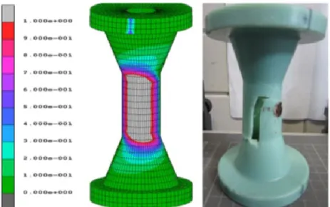
Later Smits, Van Hemelrijck, Philippidis and Cardon in 2005 [11] analyzed the previous work by Welsh and Adams. Carrying out the analysis about a finite element that consisted of different types of specimens and comparing the results with experimental tests where the strains were acquired with an extensometer and an optical system, they defined a stacking sequence [( 45/0)−+ 4/ 45]
𝐴 −
+ used as the standard for all samples.
In the figures 1.22-1.23 there are the results of the analysis for the main strains and the shear strains.
Chapter1 STATE OF ART
- 25 -
Figure 1.22 Strain along the main direction in the four cruciform geometries [11]
Chapter1 STATE OF ART
- 26 -
The geometry test piece A is the constant thickness and has a connection between the arms. For this reason, the main strains are lower in the centre area than in the arms, with consequent breaking in the latter. This is because the area that absorbs the load is greater in the centre. Scholars have thus reshaped both the thickness of the central area and the connecting rays at the intersection of the arms. In this figure C, we see these leads to the geometry where the strains are high in the biaxial loading zone and the breakage will occur in the centre of the specimen. Also the geometry D like that C has a presence of strains in the biaxial loading zone and will ensure a break into the centre of the specimen, but the second has more constant strains and a lower decrease of the same. In addition, we can say that because of the lower shear strain, therefore, this kind of phenomenon it is chosen as the best geometry. This confirms the hypothesis that for fibre-reinforced laminates the best solution is to reduce the central thickness.
1.3.2 Shape for polymeric materials
Using the Arcan machine, the number of loading directions is given by the number of holes on the device, but the loading domain is discrete. So the researchers N. Arnaud et al. in 2014 [13], starting from this device have studied a way to apply, continuously, load spectra on specimens. To carry out this, they used a tubular specimen.
Figure 1.24 Types of specimens for the biaxial tests of Arnaud. 3D CAD model and axisymmetric 2D model: (a) straight edge, (b) cleaned edge, (c) pecking with a cleaned edge, (d) chamfered
Chapter1 STATE OF ART
- 27 -
The study was based on 5 different geometries, all related to the tubular specimen (fig. 1.24). FEM tests have shown that the geometries C and E prove to be the best to determine a biaxial stress state.
In 2015 Chowdhury and Wang [14] studied the effects of biaxial stresses on a specimen in adhesive material, specifically FM355 (a particular type of epoxy adhesive). The aim was to find a particular geometry of the specimen that respected the criteria of the biaxial tests. The researchers did experimental tests on three different sample configurations, comparing the results with those obtained from FEM tests.
Figure 1.25 Typologies A, B and C of specimens analyzed by Chwdhury
In 2016 Zarouchas and Nijssen [15] performed biaxial tests on a new specimen geometry, made of EPIKPTE MGS Paste 135 / G adhesive, in order to understand how best to adapt the adhesive material to create junctions on the leading edge of the turbine blade.
Chapter1 STATE OF ART
- 28 -
The geometric configuration was a tubular type with a reduced measured thickness.
The tests were carried out at controlled load and at biaxial tension ratio (ratio between normal tension and cutting tension in the measure indicated) constant for each individual test.
Measurements of the strains were made with strain gauges oriented at 0 °, 45 ° and 90 ° respect to the longitudinal axis of the specimen.
The comparison obtained between experimental data and the FEM model shows that the latter provides a very precise point of the break. In fact, it can be seen from figure 1.26 the position of the break obtained experimenting through numerical forecasts.
Figure 1.26 Comparison between numerical results and experimental observations of Zarouchas and Nijssen
As for the hyperelastic adhesives, the specimen used in 1999 Dunkan has defined a specimen of HKL material, with each square of 45mm and a thickness of 1.6mm. Once that it was put on his test machine, the measure became 28mm.
Two types of tests were experimented: one consisted of the square-shaped specimen and the other of the same shape, but with the corners removed in order to alleviate any concentration of stress.
Chapter1 STATE OF ART
- 29 -
Figure 1.27 Schematic diagram of a biaxial specimen according to Duncan. The dotted part shows how the corners have been removed for some analysis
During this experiment of Brieu and Diani [12], the specimen, in order to validate the biaxial test, must be uniformly grasped during the test. The dimensions of the specimen, in this case, are related to the radius of connection between the arm and the measured area, which must be provided in such a way to guarantee the biaxial load in the centre of the specimen (fig. 1.28). Obviously, it can be noted that the variation of R will also vary the behaviour of the specimen submitted to the test.
Figure 1.28 Specimen dimensions of Brieu et al.
Hollenstein, Helfenstein,and Mazza in 2009 [17] tested a cruciform specimen, with 5 notches on each arm (see fig. 1.29).
Chapter1 STATE OF ART
- 30 -
Figure 1.29 Hollenstein et al. specimen
Thanks to the notches, the influence of the transition from uniaxial stress in the arms to the biaxial ones in the measured area is reduced.
The objective of the FEM analysis has reached. In fact, to maximize the area in which a biaxial load acts homogeneously, a series of deductions are made and parameterized in this way :
• Width w • Length l
• Distance from the loaded edge u
• Distance between the centre of two consecutive notches d
Chapter1 STATE OF ART
- 31 -
Hollenstein, Helfenstein, and Mazza [17] used these parameters as variables of an optimization algorithm. So, starting from the results of a FEM code, to maximizes the size of the square region in which a uniform stress state acts. This is based on two conditions:
• the main stresses acting at each point must differ from each other by 5% • the main stress acting at each point must not differ more than 1% from that acting in the centre of the specimen.
The study, thanks to the symmetry, was performed on a quarter of the specimen and the stress state was considered plane. The final solution envisaged the area of the test specimen by comparing a geometry with 4 notches on the specimen arms with the one previously studied by Mazza. The tests about Finite Elements were aimed at finding which model was the most extended into the biaxial area. The numerical models have been discretized Quad elements, whose membranous type of freedom, is the translational one in the plane. Making sure that the only thing to vary in the two models was the geometry, you could make a comparison between the two types of specimens.
When carrying out studies at the FEM, it is always necessary to define the constitutive models of the material that define their laws. For this kind of material the laws of the stress -strain curve are always based on elastic models, but with a high non-linear behaviour.
There are different patterns of hyperelastic behaviour and they are all linked to coefficients that are defined by experimental tests.
The model assumed prevalently in all the studies seen previously takes the model name of Mooney-Rivlin and assumes the trend of the curve with the help of coefficients whose values were found by Chevalier and Marco in a work of 2002 [16], through a series of experimental data collected on uniaxial and biaxial tests. The same scholars have validated a second behaviour model that takes the name of Ogdeon and that was used in the study by Hollenstein, Helfenstein and Mazza in order to understand what statistical results are correct for the two geometric models and for the two material models. We are closer to the limits imposed for biaxial behaviour.
Chapter1 STATE OF ART
- 32 -
In 2011 Schmidt, Bergamini, Kovacs and Mazza [18], starting from Helfenstein's study on the form of the specimen, developed a series of biaxial tests on an elastomer material for the study of Elastomeric Dielectric Actuators.
These actuators are nothing more than a combination of polymer membranes coated with layers of conductive material which act as electrodes and, if subject to voltage, contract in the thickness direction and expand into the plane generating a biaxial stress state.
Nonlinear dependence allows modelling this type of materials with hyperelastic strend.
The author's study is aimed at carrying out a series of biaxial tests in order to find the best function to define the strain energy density.
The instrumentation used for the tests is that of the ETH Zurich and allows a separated control of forces and displacements on the four actuators. It has been widely demonstrated that the specimen must be used for the presence of five notches on each side to reduce the influence of the transition from the uniaxial stress state in the arms into the equibiale zone in the centre.
Chapter1 STATE OF ART
- 33 - References
[1] Alan Hannon, Peter Tiernan, “A review of a planar biaxial tensile test system for sheet metal”, Journal of material processing technology 198 (2008) 1-13.
[2] A. Makinde, L. Thibodeau, KW. Neale, Development of an apparatus for biaxial testing using cruciform specimens, Exp. Mech. 1992, 32(2):138-44
[3] N. Bathnagar, R. Bhardwaj, P. Selvakumar, M. Brieu, “Development of a biaxial tensile test fixture for reinforced, Polymer Testing”, Journal of material processing technology 26 (2007) 154–161
[4] A. Smits, D. Van Hemelrijck , T.P. Philippidisand, A. Cardon, Design of a cruciform specimen for biaxial testing of fiber reinforced composite laminates, Composites Science and Technology 66(2006)964-975
[5] - J.Y. Cognard, P. Davies, B. Gineste, L. Sohier (2004). Development of an improved adhesive test method for composite assembly design. Composites Science and Technology Volume 65, Issues 3–4, Pages 359-368
[6] E. Lamkanfi, W. Van Paepegem, J. Degrieck, C. Ramault, A. Makris, D. Van Hemelrijck, Strain distribution in cruciform specimens subject to biaxial loading conditions. Part 1: Two dimentional versus three-dimentional finite element model, Polymer Testing 29(2010)7-13
[7] A. Makris, T. Vandenbergh, C. Ramault, D. Van Hemelrijck, E. Lamkanfi, W. Van Paepegem, Shape optimization of a biaxally loaded cruciform specimen, Polymer Testing 29(2010)216-223
[8] I. Guelho, L. Reis, M. Freitas, B. Li, J.F.A. Madeira, R.A. Clàudio, Optimization of cruciform specimen for low capacity biaxial testing machine, (2013)
[9] - E Mönch, D Galster (1963). A method for producing a defined uniform biaxial tensile stress field. British Journal of Applied Physics, Volume 14, Number 11 [10] J. S.Welsh, D. F.Adams (2002). An experimental investigation of the biaxial strength of IM6/3501-6 carbon/epoxy cross-ply laminates using cruciform
Chapter1 STATE OF ART
- 34 -
specimens. Composites Part A: Applied Science and Manufacturing, Volume 33, Issue 6, Pages 829-839
[11] A.Smits, D.Van Hemelrijck, T.P.Philippidis, A.Cardon (2006). Design of a cruciform specimen for biaxial testing of fiber reinforced composite laminates. Composites Science and Technology. Volume 66, Issues 7–8, Pages 964-975 [12] - M. Brieu, J. Diani, N. Bhatnagar, “A new fixture for uniaxial testing machine –A validation for hyperelastic behaviour rubber-like materials”, I. J. of Testing and Evaluation, Vol. 35, N. 4
[13] - N. Arnaud, R. Créac0hcadecn, J.Y. Cognard (2014). A stress/compression– torsion test suited to analyze the mechanical behaviour of adhesives under non-proportional loadings. International Journal of Adhesion and Adhesives Volume 53, Pages 3-14
[14] - N. T. Chowdhury, J. Wang, W. K. Chiu (2015). Design of a Flat Plate Specimen Suitable for Biaxial Tensile Tests on Polymer Materials
[15] – D. Zarouchas, R. Nijssen (2016). Mechanical behaviour of thick structural adhesives in wind turbine blades under multi-axial loading. Journal of Adhesion Science and Technology, 30:13, 1413-1429
[16] - L. Chevalier, Y.Marco, 2002. Tools for Multiaxial Validation of Behaviour Laws Chosen fon Modeling Hyper-elasticity of Rubber-like Materials. Polymer Engineering And Science, vol.42, 280-298..
[17] - Helfenstein J, Hollenstein M, Mazza E (2009). Investigation on the optimal specimen design for planar-biaxial materials testing of soft materials. Proc. 6th Eur. Conf. Cost. Models for Rubber, 371-376.
[18] - A. Schmidt, A. Bergamini, G. Kovacs, E. Mazza (2011). Multiaxial Mechanical Characterization of Interpenetrating Polymer Network Reinforced Acrylic Elastomer. Experimental Mechanics, Volume 51, Issue 8, pp.1421–1433
Chapter2 STUDY OF A NEW EQUIPMENT FOR BIAXIAL TEST
- 35 -
Chapter 2
The study of a new equipment for biaxial tests
2.1 Technical characteristics and components of the equipment
All the equipments described in the state of the art are not able to pursue the main objective of the thesis that is to create equipment that can be mounted on a universal test machine, so with vertical positioning, and which allows to modify the force between the two traction axles simply by changing some mechanical elements. This work concerns the realization of capable equipment to transmit the input from a single direction along both the X and Y axes, in order to characterize composite or polymeric materials (figure 2.1) according to a biaxial scheme.
Figure 2.1 New equipment
The equipment is designed in order to distribute the force in both directions symmetrically.
The technical design specifications of the biaxial testing equipment are: - Maximum tensile load capacity for each specimen arm 10,000 [N] - Frequency not lower than 5 [Hz]
Chapter2 STUDY OF A NEW EQUIPMENT FOR BIAXIAL TEST
- 36 - - Load group consisting of:
• Hydraulic clamps • Spiral washers
• Locking slider for grippers - Chassis group consisting of: • Support box
• Eight support arms • Connection axes
- Group for the transmission of movement consisting of: • Connecting rods
• V-shaped cranks
The individual components that reach the equipment through their CAD drawings will be illustrated below.
2.1.1 Loading group
The load group refers to the system of components (hydraulic clamps, spiral washers and sliders) useful to grasp the specimen and to apply it to biaxial load.
o Hydraulic clamps (MTS model 647) [1]
The hydraulic clamps have the function of locking and holding the specimen in the same way in the test area, so that the tests have more precision and repetitiveness. Thanks to their large clamping and alignment ability, deflection strains are reduced. Specimen slippage can invalidate test, especially during tensile and compression cycles. In addition, the hydraulic pressure of the external circuit allows testing on several types of materials.
Chapter2 STUDY OF A NEW EQUIPMENT FOR BIAXIAL TEST
- 37 -
Table 2.1 Grip specifications
Figure 2.3 CAD modelHydraulic Wedge Grip MTS 647
The used wedges have the useful saw teeth surfaces. It makes possible the clamping capacity of the specimens’ increase during the tests.
The grippers are linked to the slider through the spiral washers as shown in the following figure 2.4.
Chapter2 STUDY OF A NEW EQUIPMENT FOR BIAXIAL TEST
- 38 -
Figure 32.4 CAD model of connection between Hydraulic Wedge Grip MTS 647, spiral washers and relative slider
o Spiral washers (MTS model 601) [2]
These accessories are used to connect the different elements of the thrust to compensate the possible presence of clearance.
If the preload between the elements of the assembly has to be changed the spiral washers can be fixed up.
They are placed on the top of connection pins called connector studs.
Figure 2.5 CAD model SPIRAL WASHERS model 601
o Sliders
The slider is the element that allows the gripper to be fixed in the right position by the spiral washer through a special threaded central hole.
Chapter2 STUDY OF A NEW EQUIPMENT FOR BIAXIAL TEST
- 39 -
During the test, these sliders are transported into the box where there are holes.
Along the slider, there are channels that have the function of housing metal spheres, which allow obtaining the rolling friction rather than the sliding friction, with a consequential increase in accuracy and lower friction losses. At the end, there are some seats where the basic arms will be added to the movement of the equipment through the pins.
Figure 2.6 CAD model of the slider
2.1.2 The frame assembly
The frame assembly is the set of all the components of the machine. These elements are supported so that the deviation of the movement can be carried out into two orthogonal directions, X and Y.
This is illustrated below by according to the CAD representation. o Box
It is the real support of the structure on which all the components are constructed. It has the important function to resist the weight of the components, and, the forces that are discharged by kinematics.
It is provided with holes that allow both movement of the slider, and the locking, by the special threaded element related to the monoaxial traction machine chosen to perform the tests.
![Figure 1.22 Strain along the main direction in the four cruciform geometries [11]](https://thumb-eu.123doks.com/thumbv2/123dokorg/2761196.1053/34.892.238.744.82.572/figure-strain-main-direction-cruciform-geometries.webp)