5 Firmware development
5.1 Overview
This chapter presents the development work of the firmware for the LEON-2 processor featuring the I2C/SPI interface
As first an explanation of why Assembly is the most suitable language for this project is given. Then key concepts to understand the Sparc V8 ISA [8] are presented with programming guidelines for the optimization of the code. Finally a detailed case example is presented referring to the programming concepts express in the previous section.
5.1.1 Reasons to choice Assembly as programming language
Due to the fact that the entire flow of the I2C/SPI interface development has been followed getting a deep knowledge of the architecture of the interface, of the inner mechanisms and of the critical paths, Assembly has been chosen as the most suitable language for the system level test and the development of the interface drivers.
The embedded software, in fact, to reduce the system design cost and to improve the performance of the system needs to be optimized exploiting the characteristics of underlying hardware and the Assembly has the closer correspondence between the actions to be done and what is really performed by the processor respect to other high level languages like C or C++ . It also gives powerful tools for the debug session.
5.2 SPARC V8 ISA
SPARC [8] is a CPU instruction set architecture (ISA), derived from a reduced instruction set computer (RISC) lineage with 32-bit integer and 32-, 64-,and 128-bit IEEE Standard 754 floating-point as its principal data types.
It defines general-purpose integer, floating-point, and special state/status registers and 72 basic instruction operations, all encoded in 32-bit wide instruction formats.
The load/store instructions address a linear, 232-byte address space. In addition to the floating-point instructions, SPARC also provides instruction set support for an optional implementation-defined coprocessor. Hereafter we introduce the basics of SPARC assembly language programming. We begin by considering the structure of an assembly language program, then we describe the names and uses of the registers and some of the basic assembly language operations: set, load, store, add, sub, and mov.
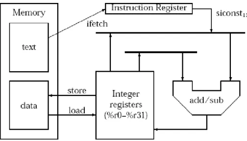
Figure 5-1 provides a graphical illustration for several of the operations that we introduce in this section. In particular, this figure illustrates the data paths used in the load, store, addition, and subtraction operations. The set and mov operations are synthetic (or pseudo) operations, this means that the assembler translates these operations into one or more SPARC operations when it assembles the program.
Figure 5-1: Load, store, add, and subtract operations
After this a subset of the SPARC branching operations are presented. In particular, we introduce the operations that provide conditional and unconditional branching based on the bits in a condition code register. Finally we consider the use of register windows on the SPARC for the ordinary procedure call, for the optimized leaf procedure and for the interrupts handling.
5.2.1 Assembly
Assembly [19] [20] language programs are line-oriented. The assembler translates an assembly language program one line at a time and it recognizes four types of lines:
• Empty lines: A line that only has spaces or tabs (i.e., white space) is an empty line. Empty lines are ignored by the assembler.
• Label definition lines: consists of a label definition. A label definition consists of an identifier followed by a colon (“:”). As in most programming languages, an identifier must start with a letter (or an underscore) and may be followed by any number of letters, underscores, and digits. In an assembly language program, a label is simply a name for an address. On the SPARC an address is a 32-bit value. As such, labels are 32-bit values when they are used in assembly language programs.
• Directive lines: consists of an optional label definition, followed by the name of an assembler directive, followed by the arguments for the directive and instruction lines. Useful directives are:
o .data directive is used to start variable declarations section. Each group of variable declarations should be preceded by a .data directive.
o .text directive is used to start assembly language instructions. Each group of assembly language instructions should be preceded by a .text directive. o .word directive is used to allocate and initialize space for a variable. A
variable declaration starts with a label definition (the name of the variable), followed by a .word directive, and followed by the initial value for the variable.
o .set directive is used to define a symbolic constant. o .include directive is used to include source (header) files.
• Instruction line: consists of an optional label definition, followed by the name of an operation, followed by the operands. Every line can conclude with a comment. Comments begin with the character “!”. Whenever it encounters a “!”, the assembler ignores the “!” and the remaining characters on the line.
5.2.2 Integer registers
The SPARC integer unit provides thirty-two general purpose registers. Each integer register holds 32-bits. The integer registers are called %r0 through %r31. In addition to the names, the integer registers have alternate names (aliases) as shown in Table 5-1.
Table 5-1: Aliases for the integer registers
The alternate names reflect the uses of the registers when procedures use register windows (see section 5.2.5 for more details). Note that the value stored in %r0 is always zero and cannot be altered. If an instruction specifies %r0 is used as the destination, the result is simply discarded. It is not an error to execute an instruction that specifies %r0 as the destination for the result; however, the contents of %r0 will not be altered when this instruction is executed.
5.2.3 Instructions
5.2.3.1 The set operation
The set operation can be used to load a 32-bit signed integer constant into a register. Every set instruction has two operands: the 32-bit value followed by the destination register. Table 5-2 summarizes the set operation:
Table 5-2: The set operation
5.2.3.2 The load and store operations
The SPARC is based on the load/store architecture. This means that registers are used as the operands for all data manipulation operations. The operands for these operations cannot be in memory locations. Table 5-3 summarizes the load and store operations:
Table 5-3: The load and store operations
5.2.3.3 The addition and subtraction operations
The SPARC uses 2’s complement representation for signed integer values. Signed additions and subtractions are performed using 32-bit arithmetic (the source and destination values are 32 bits). Table 5-4 summarizes the signed addition and subtraction operations provided by the SPARC. The SPARC provides two instruction formats for each of the arithmetic operations. Both formats use three explicit operands—two source operands, and a destination operand. In the first format both of the source operands are in registers. In the second format, one of the source operands is in a register while the other is a small constant value. This constant value may be negative or positive; however, its 2’s complement representation must fit in 13 bits
Table 5-4: The addiction and subtraction operations
5.2.3.4 The mov operation
The mov operation is used to copy the value stored in one register to another register. This operation can also be used to load a small integer value into a register. Table 5-5 summarizes the mov operations.
Table 5-5: The mov operation
5.2.3.5 The condition code register
The condition code register on the SPARC has four bits: Z (Zero), N (Negative), C (Carry), and V (oVerflow). The standard arithmetic operations (e.g., addition and subtraction) do not update the bits in the condition code register. Instead, there are special operations that update the condition code register. Table 5-6 summarizes a collection of operations that update the bits in the condition code register. The names for these operations have a suffix of “cc” to indicate that they update the bits in the condition code register. In most cases, the effect that an operation has on the condition codes is just what you would expect. Most of these operations set the Z bit when the result of the operation is zero, and clear this bit when the result is nonzero. Similarly, most of these operations set the N bit when the result of the operation is negative, and clear this bit when the result is nonnegative. The V bit is usually set when the (signed integer) result of the operation
cannot be stored in 32 bits, and cleared when the result can be stored in 32 bits. Finally, the C bit is set when the operation generates a carry out of the most significant bit, and cleared otherwise.
Table 5-6: Operations that update the CCR
5.2.3.6 Branching operations
The SPARC provides 16 basic branching operations. These operations are summarized in Table 5-7. Note that the first two operations, ba (branch always) and bn (branch never), are unconditional the operation specifies whether the branch is taken. The remaining operations are conditional branching operations. When these operations are used, the branch is only taken when the specified condition is met.
The condition is satisfied if the Boolean expression results in the value 1; otherwise (if the expression results in 0), the condition is not satisfied and the processor continues with sequential execution of instructions. The target specified in an assembly language instruction is a label defined by the program. SPARC assemblers provide a special (synthetic) operation, nop, for situations when it is not convenient to put a useful instruction in the delay slot of a branch instruction. In assembly language a nop instruction has no operands (i.e., a nop instruction is fully specified by the name of the operation). When a nop instruction is executed, it does not alter any of the registers or values stored in memory. However, the use of nop instructions causes the processor to execute more instructions and, as such, increases the time required to execute the program.
The SPARC keeps track of the instructions to execute using two program counters: PC, and nPC. The first program counter, PC, holds the address of the next instruction to execute. The second program counter, nPC, holds the next value for PC. Usually, the SPARC updates the program counters at the end of each instruction execution by assigning the current value of nPC to PC, and adding 4 to the value of nPC. When it executes a branching operation, the SPARC assigns the current value of nPC to PC and then updates the value of nPC. If the branch is taken, nPC is assigned the value of the target specified in the instruction; otherwise, nPC is incremented by 4. The branch delay slot arises because the PC is assigned the old value of nPC (before nPC is assigned the target of the branch).
5.3.1 Bitwise operations
Table 5.8 summarizes the bitwise operations of the SPARC and Table 5-9 shows their conditional code version. Like the other data manipulation operations (e.g., add, sub, smul, sdiv, etc.), there are two instruction formats for each of the bitwise operations. Both formats use three explicit operands—two source operands and a destination operand. In the first format, both of the source operands are in registers. In the second format, one of the source operands is in a register, the other is a small constant value. This constant may be positive or negative; however its 2’s complement representation must fit in 13 bits—the SPARC does sign extend this value.
Table 5-8: Bitwise operations
Table 5-9: Bitwise operations conditional code version
5.2.4 Addressing
The SPARC supports two addressing modes: register indirect with index and register indirect with displacement. In the first mode, the effective address is calculated by adding the contents two integer registers. This addressing mode is commonly used to access an array element: one of the registers holds the base address of the array, the other holds the (scaled) index of the element.
In the second mode, the effective address is calculated by adding a 13-bit signed integer constant to a register. This addressing mode can be used with pointers to structures: the register holds the address of the structure and the integer constant specifies the offset of the member (field) being accessed. Register indirect with displacement addressing is also commonly used when accessing items on the runtime stack (e.g., parameters and local variables). Table 5-10 summarizes the addressing modes supported by SPARC assemblers
and Table 5-11 shows the addressing mode for the load and store instructions. In addition to the two basic addressing modes, SPARC assemblers recognize register indirect addressing and a limited form of direct memory addressing. Direct memory addresses are limited to values that can be expressed in 13-bits when sign-extended (i.e., very small addresses and very large addresses).
Table 5-10: Addressing modes
Table 5-11: Load and store addressing
5.2.5 Register windows and procedure calls
The SPARC integer unit as told before provides thirty-two general purpose registers:
Table 5-12: Aliases for the general registers
The alternate names reflect the uses of the registers when procedures use register windows. The global registers (%g0–%g7) are shared by all procedures. The output
registers are used for parameters when calling another procedure. That is, the output registers are outputs from the caller to the called procedure. The local registers (%l0–%l7) are used to store local values used by a procedure. The input registers (%i0–%i7) are used for the parameters passed into the procedure. That is, the input registers are inputs passed from the caller to the called procedure.
Considering the relationship between the output and input registers, the trick is to make the caller’s output registers the same as the called procedure’s input registers. On the SPARC, this is done using overlapping register windows.
All procedures share the global registers (%g0–%g7). The remaining registers, %o0–%o7, %l0–%l7, and %i0–%i7, are called a register window.
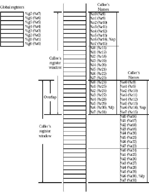
When a procedure starts its execution, it allocates a set of 16 registers (using the save instruction as described in the following section). The new register set provides the procedure with its own output and local registers (%o0–%o7 and %l0–%l7). The procedure’s input registers (%i0–%i7) are overlapped with the caller’s output registers. Figure 5-2 illustrates the overlapping of register windows between the caller and the called.
In addition to the register names we have discussed, Figure 5-2 introduces two new names: %sp and %fp. The first of these, %sp, denotes the stack pointer. In an assembly language program, %sp is simply another name for %o6. Similarly, %fp denotes the frame pointer and is simply another name for %i6. We will discuss the special uses of these registers (and hence the additional names) in the next sections. Every SPARC as the LEON has 8 global registers, plus a circular stack of 2 to 32 register sets. Each register set has 16 registers.
5.2.5.1 Save and Restore
The current window in the integer registers is given by the current window pointer (CWP). The CWP is stored in the lower five bits of the processor status register (PSR). The save and restore instructions let the programmer to manipulate the CWP.
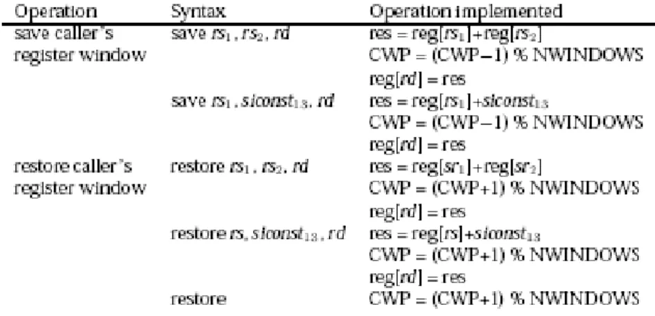
Table 5-13 summarizes the SPARC save and restore operations. SPARC assemblers provide two instruction formats for save instructions and three formats for restore instructions. Both formats for the save instruction and the first two formats for the restore instruction use three explicit operands, two source operands and a destination operand. In the first format, both source operands are in registers.
Table 5-13: Save and Restore operations
5.2.5.2 Stack management
The operands of the save instruction are commonly used to allocate space for a stack frame.(refear to the Sparc manual for more details [8])
However, to the save and restore instructions correctly, you must allocate and maintain a runtime stack. The runtime stack grows from higher to lower addresses. The stack pointer (%r14, %o6) should be aligned on an 8 byte address at all times. In most cases, the restore instruction with no arguments is used to restore the caller’s register window. However, occasionally is used the other versions of this instruction to return a value from a procedure.
5.2.5.3 Procedure calling conventions
From the caller’s perspective using register windows does not change anything about how it interacts with the called procedure. The caller still puts the outgoing parameters in registers %o0–%o5 (%r8–%r13) and expect the result in %o0 (%r8). Moreover, the caller may assume that registers %g0, %g2–%g7, %o6 (%sp), %l0– %l7, and %i0–%i7 will not be altered by the called procedure. Finally, the caller uses the call instruction introduced in the previous lab to transfer control to the called procedure. From the perspective of the called procedure, things have changed quite a bit. As
soon as control is transferred to the procedure, it needs to save to the caller’s register window. In the body of the procedure, you can modify %g1, %i0–%i5, %l0–%l7, and %o0–%o6. You could also modify %i7; however, %i7 holds the return address, so it’s not a good idea to change it. Finally, just before returning control to the caller, the called procedure needs to restore the caller’s register window. The instruction used to restore the caller’s register window is usually put in the branch delay slot of the instruction used to return control to the caller. Because the caller’s register window has not been restored when the called procedure issues the return instruction, the return instruction needs to use %i7 in calculating the return address instead of %o7 (%r15). SPARC assemblers provide the ret instruction for this purpose. Table 5-14 summarizes the call and return instructions.
Table 5-14: Procedure calling instructions
5.2.5.4 Leaf procedures on the SPARC
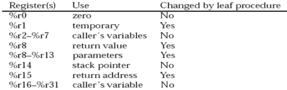
The SPARC Architecture Manual describes a class of procedures called “optimized leaf procedures.” A leaf procedure is a procedure that does not call any other procedures. Optimized refers to restrictions placed on the procedure’s use of the registers. Table 5-15 summarizes register uses for optimized leaf procedures.
This table specifies which registers can be modified by a leaf procedure. Registers %r8–%r13 are used for parameters passed to the leaf procedure. The first parameter (i.e., the leftmost parameter) should be placed in %r8, the next in %r9, and so forth. Note that %r8 is used for the first parameter and the return value.
Beyond the registers used to pass parameters to the leaf procedure, there are a few other conventions in Table 5-15 that are worth noting. Register %r1 can always be used as a temporary register and the caller cannot assume that it will retain its value across a call to a leaf procedure. The stack pointer is stored in %r14. Note that a leaf procedure should not alter the value stored in register %r14. Finally, note that the return address (actually, the address of the call instruction used to call the leaf procedure) is stored in register %r15. A leaf procedure can alter this register; however, it will be difficult to return to the point of the call if you alter the value in %r15.
An optimized leaf procedure should only alter the values stored in registers %r1 and %r8–%r13. If the leaf procedure requires more local storage than these registers provide, or if the parameters do not fit in these registers, the leaf procedure cannot be implemented as an “optimized” leaf procedure.
In assembly language, a procedure is a block of instructions. The first instruction in this block is labelled by the name of the procedure. Table 5-16 summarizes the operations used to call and return from optimized leaf procedures.
Like the branching operations, these operations have a branch delay slot. The call and link operation saves the current value of the PC in %r15, updates the PC, and sets the nPC to the address specified in the call. The retl operation updates the PC and sets to nPC to the contents of %r15 plus eight. The “plus eight” is needed to skip over the call instruction and the instruction in the delay slot of the call.
5.2.5.5 Interrupt handling in the SPARC
A trap is a vectored transfer of control to the operating system through a special
trap table that contains the first 4 instructions of each trap handler. The base address of the table is established by software in an IU state register (the trap base register, TBR). The displacement within the table is encoded in the type number of each trap. Half of the table is reserved for hardware traps, and the other half for software traps generated by trap (Ticc) instructions. A trap causes the current window pointer (CWP) to advance to the next register window and the hardware to write the program counters into two registers of the new window. The trap handler can access the saved PC and nPC and, in general, can freely use the 6 other local registers in the new window.
A trap may be caused by an instruction-induced exception, or by an external interrupt request not directly related to a particular instruction. Before executing each instruction, the IU checks for pending exceptions and interrupt requests. If any are present, the IU selects the one with the highest priority and causes a corresponding trap to occur.
An exception or interrupt request can cause either a precise trap, a deferred trap,or an interrupting trap.
A precise trap is induced by a particular instruction and occurs before any
program-visible state is changed by the trap-inducing instruction.
A deferred trap is also induced by a particular instruction, but unlike a precise trap,
it may occur after program-visible state is changed by the execution of one or more instructions that follow the trap-inducing instruction. A deferred trap may occur one or more instructions after the trap-inducing instruction is executed.
An interrupting trap may be due to an external interrupt request not directly
related to any particular instruction, or may be due to an exception caused by a particular previously executed instruction. An interrupting trap is neither a precise trap nor a deferred trap. User-application programs do not “see” traps unless they install user trap handlers for those traps (via calls to supervisor software). Also, the treatment of implementation-dependent “non-resumable machine-check” exceptions can vary across systems. See Chapter 7, “Traps,” on the SPARC architecture manual [8] for a complete description of the default trap model.
Progressive location number
5.3 Driver and test creation for the I
2C/SPI interface
According with the programming guidelines shown in the section 5.2 we present a case example of an assembly test written to perform the Transmission test for the I2C/SPI interface. The structure of the test is shown and a detailed explanation of the self checking test bench implementation, of the interrupt handler and of the main macros used is given: File: branca_I2C_SPI_TX1_001.S
Variables definition .data
.global exp_val,_exp_val,act_val,_act_val,irqtbl,_irqtbl Table used for Interrupt Controller purposes
_irqtbl: irqtbl:
.word 0,0,0,0,0,0,0,0,0,0,0,0,0,0,0,0
This table has to be filled by a maximum of N_word words representing the expected values read from the peripheral related registers.
Each value can be stored in this table by the .word directive as in the following:
.word 0x0A001F3F !1! UART CONTROL register, reset value
_exp_val: exp_val: .word 0x000000AA !1! .word 0x000000AA !2! .word 0x000000AA !3! Exadecimal value (32 bit) Comment
.word 0x0000FCAA !4! .word 0x100000AA !5! end_exp_val:
This fills the empty part of the exp_val table in order to keep fixed its size .space ( N_word * 4 - ( end_exp_val - exp_val ) ) , 0x00
This table is filled with 0-values at boot time and it is updated, during simulation, with the actual values read from the peripheral related registers
_act_val: act_val:
.space N_word * 4 , 0x00 Interrupt handler definition .text
.global _irq_1_handler, irq_1_handler, _irq_2_handler, irq_2_handler .global _irq_3_handler, irq_3_handler, _irq_4_handler, irq_4_handler .global _irq_5_handler, irq_5_handler, _irq_6_handler, irq_6_handler .global _irq_7_handler, irq_7_handler, _irq_8_handler, irq_8_handler .global _irq_9_handler, irq_9_handler, _irq_10_handler, irq_10_handler .global _irq_11_handler, irq_11_handler, _irq_12_handler, irq_12_handler .global _irq_13_handler, irq_13_handler, _irq_14_handler, irq_14_handler .global _irq_15_handler, irq_15_handler
_irq_1_handler: irq_1_handler: _irq_2_handler: irq_2_handler: _irq_3_handler: irq_3_handler: _irq_4_handler: irq_4_handler: _irq_5_handler: irq_5_handler: _irq_6_handler: irq_6_handler: _irq_7_handler: irq_7_handler: _irq_8_handler: irq_8_handler: _irq_9_handler: irq_9_handler: _irq_10_handler: irq_10_handler: _irq_11_handler: irq_11_handler: _irq_12_handler:
irq_12_handler: _irq_13_handler: irq_13_handler: _irq_14_handler: irq_14_handler: _irq_15_handler: irq_15_handler: RESERVED REGISTERS
- %g7 : it holds the address of the last acquired value - %g6 : error-location address register
- %g5 : error register
- %g4 : end-of-simulation register
Initialising reserved registers
.global _leon_test, leon_test _leon_test: leon_test: set act_val , %g7 clr %g5 clr %g4 clr %g6
! irq(13) <= master interrupt - Enable mask: 0x2000 ! irq(12) <= slave interrupt - Enable mask: 0x1000 !
! %o1 bcr data ! %o2 bcr1 data ! %o3 txr/txr1 data ! %o4 cr data
! %o5 transfer time ! %o6 cr1 data
set PREGS , %l6
SETUP: MASTER – TX, Call to the transfer setup procedure call SETUP_TX
nop
TX of 1 BYTE and ACK received, Registers setting ! 1 byte transfer master
set 0x00000000 , %o1
! 1 byte transfer slave
set 0x00000000 , %o2
! byte to transmit
set 0x100000AA , %o3 ! command master set 0x00000010 , %o4 ! command slave set 0x00000000 , %o6 ! time
set 0xAF , %o5
Call to the transfer setup procedure, in the delayed slot of the call there is a nop instruction call TX
nop
Transfer check
Trace is a Macro. This macro updates the act_val_table with the acquired value and updates the pointer to the table %g7 that holds the address of the last acquired value.
.macro trace st %g3 , [ %g7 ] add 4 , %g7 , %g7 .endm !TX check (1) ld [%l6+RXR1],%g3 trace;
.
.
.
Jump to the END procedure
ba END
nop
Transfer setup procedure SETUP_TX:
set PREGS , %l6
! enable IRQCTRL to accept irq requests from I2C_SPI set 0x3000, %l1
st %l1 , [%l6 + IMASK]
! write in sel_reg to select I2C MODE set 0x00000001 , %l1 st %l1 , [%l6 + sel_reg]
.
.
.
Transmission optimized leaf procedure TX:
! set number of bytes master st %o1 , [%l6 + BCR] ! set number of byte slave st %o2 , [%l6 + BCR1] ! set byte to transmit
st %o3 , [%l6 + TXR] ! Enable interrupt set 0x3000, %o0 st %o0 , [%l6 + IMASK] set 0x1F , %o0 WAITING_IRQ1: deccc %o0 BNZ WAITING_IRQ1 nop ! command slave st %o6 , [%l6 + CR1] ! command master st %o4 , [%l6 + CR] ! MASK master interrupt set 0x0000, %l1 st %l1 , [%l6 + IMASK] WAITING_IRQ11: deccc %o5 BNZ WAITING_IRQ11 Nop retl nop
Our procedures of TRANSMISSION and RECEPTION that together with the SETUP procedure are the main calls of the interface drivers have been optimized using the technique described in the section 5.2.5.4. As told in this section a leaf procedure is one, that does not call (e.g. via CALL or JMPL) any other procedures. Each procedure, including leaf procedures, normally uses a SAVE instruction to allocate a stack frame and obtain a register window for itself, and a corresponding RESTORE instruction to deallocate it. The time costs associated with this are:
• Possible generation of register-window overflow/underflow traps at runtime. This only happens occasionally, but when either underflow or overflow does occur, it costs dozens of machine cycles to process.
• The two cycles expended by the SAVE and RESTORE instructions themselves • There are also space costs associated with this convention, the cumulative cache
effects of which may not be negligible. The space costs include:
o The space occupied on the stack by the procedure’s stack frame o The two words occupied by the SAVE and RESTORE instructions
Of the above costs, the trap-processing cycles are typically the most significant. Some leaf procedures can be made to operate without their own register window or stack frame, using their caller’s instead
Our procedures match the conditions for the optimisation and this lead to an improvement in the performance and to an optimization in the handle of the peripheral saving both time and space. Then according with this rules it may only safely use registers that its caller already assumes to be volatile across a procedure call, namely, %o0 ... %o5, %o7, and %g1.
Escape procedure
END: nop
Compare macro compare;
Compare macro: It compare the value between the Expected value table and the Actual value table. An “OK” message is displayed on the screen if doesn’t occur any error. If some errors occur and some values don’t match in the compare procedure the %g5 register is set and the line number of the fault and a “NOK” message are displayed.
.macro compare
! UART0 and IOPORT programming set PREGS, %l6 ! Prescaler setting ! BAUD-RATE 115200 => (system_clock)/(baud_rate*8)=26=0x1A !mov 0x1A , %l1 set UART0_SCALER , %l1 st %l1 , [%l6 + USCAL0] ! Transmitter enabling mov 0x2 , %l1 st %l1 , [%l6 + UCTRL0]
! Programming ioport-bit(15) as output line for UART TXD
set 0x8000 , %l1
st %l1 , [%l6 + IODIR]
! Sending a newline character. This allows the watcher to be reset
mov 0xA , %l1
st %l1 , [%l6 + UDATA0]
! Waiting for data transmitted 999:
andcc %l4 , 0x4 , %l4 bz 999b
nop
set act_val , %l7 1:
subcc %g7 , %l7 , %l4 ! It checks if there are still values to compare
bz 3f ! If they are finish jump to 3
nop
ld [ %g7 - 4 ] , %g2 !Load a value from the Act_value table ld [ %g7 - N_word * 4 - 4 ] , %g3!Load a value from the Exp_value table subcc %g2 , %g3 , %g0
bz 2f !If the two values match jump to 2
nop
mov 1 , %g5 !Set the error register
srl %l4 , 2 , %g6
! UART transmission of the wrong location number
! Evaluation of the 1st decimal digit (hundred) of the wrong location
mov 0x64 , %l2 mov 0x0 , %y
udiv %g6 , %l2 , %l1
! Forming an ASCII number add %l1 , 0x30 , %l3
! Digit transmitting st %l3 , [%l6 + UDATA0]
! Waiting for data transmitted 400: ld [%l6 + USTAT0] , %l4 andcc %l4 , 0x4 , %l4 bz 400b nop umul %l2 , %l1 , %l1 sub %g6 , %l1 , %l1
! Evaluation of the 2nd decimal digit (ten) of the wrong location
.
.
.
2: ! Update the address of the last acquired value sub %g7 , 4 , %g7
ba 1b nop
3:! This code refers to UART transmission of the TEST result
! Storing in l1 the ASCII code of the newline character
mov 0xA , %l1
andcc %g5 , 0x1 , %l5 ! Check if there are errors
bz 30f ! if not error jump to 30
nop
! Test failed: transmitting NOK
mov 0x4E , %l3 ! ASCII code for letter N st %l3 , [%l6 + UDATA0]
! Waiting for data transmitted 20: ld [%l6 + USTAT0] , %l4 andcc %l4 , 0x4 , %l4 bz 20b nop 30:
mov 0x4F , %l3 ! ASCII code for letter O st %l3 , [%l6 + UDATA0]
! Waiting for data transmitted 31: ld [%l6 + USTAT0] , %l4 andcc %l4 , 0x4 , %l4 bz 31b nop . . .
End of test and final_loop mov 0x40 , %g4
final_loop:
ba final_loop
nop
5.3.1.5 Interrupt handler
The LEON interrupt controller is used to prioritize and propagate interrupt requests from internal or external devices to the integer unit.
A total of 15 interrupts are handled and interrupts from 10-15 are unused by the default configuration of LEON and can be used by added IP cores.
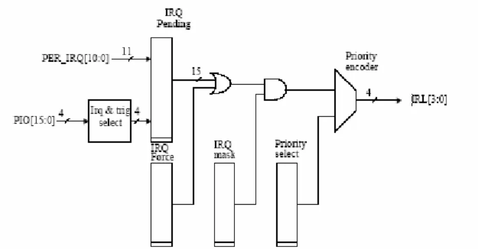
When an interrupt is generated the corresponding bit is set in the interrupt pending register (IPEND(15:1)). The pending bits are ANDed with the interrupt mask register IMASK(15:1) and then forwarded to the priority selector as shown in figure 5-3.
When the IU acknowledges the interrupt, the corresponding bit will automatically be cleared. The register ICLEAR(15:1) permit to clear manually the IRQ pending register.
After a reset the interrupt mask register is set to all zeros while the remaining control registers are undefined. Figure 5-3 shows the interrupt control block diagram.
Figure 5-3: Interrupt controller block diagram
The I2C/SPI interface master has been linked to the interrupt handler 13. The slave one has been linked to the interrupt handler 12. For the arbitration lost test, the second master has been linked to the handler 14.
The interrupt handler starts each time that the interrupt signal irq_m for the master or irq_s for the slave is asserts. The master interrupt has a priority level higher then the slave.
Hereafter an example of the interrupt handler for the slave is given:
Slave interrupt handler
irq_12_handler:
! Acknowledge interrupt set 0x00000001 , %l4 st %l4 , [%l6 + CR1] ! Clear interrupt set 0x00000000 , %l4 st %l4 , [%l6 + CR1]
! Clear pending interrupt
set 0x1000, %l4 st %l4 , [%l6 + ICLEAR] ! Timeout register set 0x1F , %l5 WAITING_IRQ331: deccc %l5 BNZ WAITING_IRQ331 nop
To re-execute the trapped instruction when returning from a trap handler you have to use this return statement
jmpl %l1, %g0
rett %l2
nop nop