The
Eur
o
p
e
an
Uni
o
n
I
n
or
de
r
t
o
pr
omot
e
publ
i
c
e
duc
a
t
i
on
a
nd
publ
i
c
s
a
f
e
t
y,
e
qua
l
j
us
t
i
c
e
f
or
a
l
l
,
a
be
t
t
e
r
i
nf
or
me
d
c
i
t
i
ze
nr
y,
t
he
r
ul
e
of
l
a
w,
wor
l
d
t
r
a
de
a
nd
wor
l
d
pe
a
c
e
,
t
hi
s
l
e
ga
l
doc
ume
nt
i
s
he
r
e
by
ma
de
a
va
i
l
a
bl
e
on
a
nonc
omme
r
c
i
a
l
ba
s
i
s
,
a
s
i
t
i
s
t
he
r
i
ght
of
a
l
l
huma
ns
t
o
know
a
nd
s
pe
a
k
t
he
l
a
ws
t
ha
t
gove
r
n
t
he
m.
≠
EDI
CT
OF
GOVERNMENT
±
EN 1993-1-8 (2005) (English): Eurocode 3: Design of steel
structures - Part 1-8: Design of joints [Authority: The
European Union Per Regulation 305/2011, Directive 98/34/EC,
Directive 2004/18/EC]
EUROpAISCHE NORM
ICS 91.010.30 May 2005 English version Supersedes ENV 1993-1-1 :1992 Incorporating Corrigenda December 2005 and July 2009Eurocode 3: Design of steel structures - Part 1-8: Design of
joints
Euroeode 3: Caleul des structures en aeier - Partie 1-8: Calcul des assemblages
Eurocode 3: Bemessung und Konstruktion von Stahlbauten - Teil 1-8: Bemessung von Anschlussen This European Standard was approved by CEN on 16 April 2004.
CEN members are bound to comply with the CEN/CENELEC Internal Regulations which stipulate the conditions for giving this European Standard the status of a national standard without any alteration. Up-tO-date lists and bibliographical references concerning such national standards may be obtained on application to the Central Secretariat or to any CEN member.
This European Standard exists in three official versions (English, French, German). A version in any other language made by translation under the responsibility of a CEN member into its own language and notified to the Central Secretariat has the same status as the official versions.
CEN members are the national standards bodies of Austria, Belgium, Cyprus, Czech Republic, Denmark, Estonia, Finland, France, Germany, Greece, Hungary, Iceland, Ireland, Italy, Latvia, Lithuania, Luxembourg, Malta, Netherlands, Norway, Poland, Portugal, Slovakia, Slovenia, Spain, Sweden, Switzerland and United Kingdom.
EUROPEAN COMMITTEE FOR STANDARDIZATION COMlTE EUROPEEN DE NORMALISATION EUROpA I HES KOMlTEE FUR NORMUNG
Management Centre: rue de Stassart, 36 B-1050 Brussels
2005 CEN All rights
of
exploitation in any form and by any means reserved worldwide for CEI\J national Members.Contents
PageIntroduction ... 8
1.] Scope ... 8
l.2 N01111ative references ... 8
1.3 Distinction between Principles and Application Rules ... 1 0 ] .4 Tenns and definitions ...
1
0 1.5 SY111bols ... 132 Basis of design ... 18
2.1 AsslIlnptions ... 18
2.2 General requirenlents ... 18
2.3 Applied forces and 1l101l1ents ... J 8 2.4 Resistance of joints ... 18
2.5 Design assunlptions ... 19
2.6 Joints loaded in shear subject to impact, vibration and/or load reversal ... 19
2.7 Eccentricity at intersections ... 19
3 Connections made \vith bolts, rivets or pins ... 20
3.] 3.1.1 3.1.2 3.2 3.3 Bolts, nuts and "vashers ... 20
General ... 20
PreJoaded bolts ... 20
Rivets ... 20
Anchor bo1ts ... 2]
3.4 Categories ofboJted connections ... 21
3.4. 1 Shear connections ... 2]
3.4.2 Tension connections ... 21
3.5 Positioning of holes for bolts and rivets ... 23
3.6 Design resistance of individual fasteners ... 24
3.6.1 Bolts and rivets ... 24
3.6.2 Injection bolts ... 28
3.7 Group of fasteners ... 29
3.8 .Longjoints ... 29
3.9 Slip-resistant connections using 8.8 or lO.9 bolts ... 30
3.9. J Design Slip resistance ... 30
3.9.2 Combined tension and shear ... 31
3.9.3 Hybrid cOl1nections ... 31
3.10 Deductions for fastener holes ... 31
3.10.1 General ... 31
3.10.2 Design for block tearing ... 32
3.10.3 Angles connected by one and other unsymmetrically connected members in tension ... 33
3.10.4 Lug ... 34
3.1 J Prying forces ... 34
3.12 Distr.ibution of forces between fasteners at the ultimate limit state ... 34
3.J3 Connections made with 3. J 3.1 General ... 35
3.13.2 Design of pins ... 35
4 \Velded connections ... 38
4.1 General ... 38
4.2 Welding consu1l1ables ... 38
4.3 Geollle1ry and dilnensions ... 38
4.3.] Typeof\veld ... 38
4.3.2 Fillet welds ... 38
4.3.3 fillet \ve1ds all rOLlnd ... 40
4.3.6 4.4
Flare groove welds ... 41
Welds with pa(~Kllt1g~ ... . 4.5 Design resistance of a fillet \veld ... 42
4.5.1 Length of welds ... 42
4.5.2 Effective throat thickness ... .42
4.5.3 Resistance of fillet welds ... .42
4.6 resistance of fillet welds all round ... 44
4.7 Design resistance of butt welds ... .45
4.7.1 Full penetration butt welds ... .45
4.7.2 Partial penetration buH welds ... .45
4.7.3 T-butt joints ... 45
4.8 Design resistance of plug welds ... .45
4.9 Distribution of forces ... 46
4.10 Connections to unstiffened tlanges ... .46
4.1] Long joints ... 48
4.12 Eccentrically loaded single fillet or single-sided partial penetration butt welds ... .48
4.13 connected by one leg ... 48
4.14 Welding in cold-formed zones ... .49
5 Analysis, classification and modelling ... 50
5.1 Global analysis ... 50
5.1.1 General ... 50
5.1.2 Elastic global ... 50
5.1.3 Rigid-plastic global analysis ... 51
5.1.4 Elastic- plastic global analysis ... 51
5.1.5 Global analysis of lat6ce girders ... 52
5.2 Classification of joints ... 54
5.2.1 General ... 54
5.2.2 Classification by stiffness ... 54
5.2.3 Classification by strength ... 55
5.3 Modelling of beam-to-column joints ... 56
6 Structural joints connecting H or 1 sections ... 60
6.1 General ... 60
6.1.1 Basis ... 60
6.1.2 Structural properties ... 60
6.1.3 Basic components of a joinL ... 6]
6.2 Design Resistance ... 65
6.2.1 Internal forces ... 65
6.2.2 Shear forces ... 65
6.2.3 Bending lnOlnents ... 66
6.2.4 Equivalent T-stub in tension ... 67
6.2.5 Equivalent T -stub in compression ... 70
6.2.6 Resistance of basic components ... 71
6.2.7 moment resistance of beam-to-column joints and splices ... 84
6.2.8 resistance of column bases with base plates ... 89
6.3 Rotational stiffness ... 92
6.3.1 Basic tllodel ... 92
6.3.2 Stiffness coefficients for basic joint components ... 94
6.3.3 End-plate joints with two or more bolt-rows in tension ... 97
6.3.4 Colulnn bases ... 98
6.4 Rotation capacity ... 99
6.4.1 General ... 99
6.4.2 Bo1ted 100 6.4.3 Welded Joints ... 100
7 Hollow section joints ... 10'1 7.1 General ... 10]
7.1.1 ... 10.1
7.1.2 Field of application ... 101
7.2 Design ... 103
7.2.1 General ... 103
7.2.2 Failure modes for hollow section 103 7.3 Welds ... 107
7.3.1 Design resistance ... 1 07 7.4 Welded joints between CHS members ... 108
7.4 . .1 General ... 1 08 7.4.2 Uniplanar joints ... 108
7.4.3 Mul1iplanarjoints ... 115
7.5 Vlelded joints between CHS or RHS brace members and RHS chord members ... 116
7.5.1 General ... 116 7.5.2 7.5.3 7.6 7.7 Uniplanar joints ... 117 Multiplanar joints ... 128
Welded joints between CHS or RHS brace members and lor H section chords ... .129
Foreword
This European Standard EN 1993, Eurocode 3: Design of steel structures, has been prepared by Technical Committee CEN/TC250
«
Structural Eurocodes»,
the Secretariat of which is held by BSl. CEN/TC250 is responsible for all Structural Eurocodes.This European Standard shall be given the status of a National Standard, either by publication of an identical text or by endorsement, at the latest by November 2005, and conflicting National Standards shall be withdrawn at latest by .March 20 lO.
This Eurocode ,""0,."",11.",,, ENV 1993-1-1.
According to the CEN-CENELEC Internal Regulations, the National Standard Organizations of the following countries are bound to implement these European Standard: Austria, Belgium, Cyprus, Czech Republic, Denmark, France, Germany, Greece, Iceland, Ireland, Italy, Latvia, Lithuania, Luxembourg, Malta, Netherlands, Norway, Poland, Portugal, Slovakia, Slovenia, Spain, Sweden, Switzerland and United Kingdom.
Background to the Eurocode programme
In 1 the Commission of the European Community decided on an action programme in the field of construction, based on article 95 of the Treaty. The objective of the programme was the elimination of technical obstacles to trade and the harmonization of technical specifications.
\Vithin this action programme, the Commission took the initiative to establish a set of harmonized technical rules for the design of construction works which, in a first would serve as an alternative to the national rules in force in the Member States and, ultimately, would replace them.
For fifteen years, the COlmnission, with the help of a Steering Committee with Representatives of Member States, conducted the development of the Eurocodes programme, which led to the first generation of European codes in the 1980s.
In 1989, the Commission and the Member States of the EU and EFTA on the basis of an agreement] between the Commission and CEN, to transfer the preparation and the publication of the Eurocodes to CEN through a series of Mandates, in order to provide them with a future status of European Standard (EN). This links de the Eurocodes with the provisions of all the Council's Directives and/or Conunission's Decisions dealing with European standards the Council Directive 8911 06/EEC on construction products - CPD and Council Directives 93/37/EEC, 92/S0/EEC and 89/440/EEC on public works and services and equivalent EFTA Directives initiated in pursuit of up the internal market).
The Structural Eurocode programme comprises the following standards generally consisting of a number of Parts:
EN 1990 Eurocode 0; Basis of Structural Design EN ]99] Eurocode 1: Actions on structures EN 1992 Eurocode 2: of concrete structures EN 1993 Eurocode 3: Design of steel structures
EN 1994 Eurocode 4: Design of composite steel and concrete structures EN 1995 Eurocode 5: Design of timber structures
EN 1996 Eurocode 6: Design of masonry structures EN 1997 Eurocode 7: Geotechnical
EN 1998 Eurocode 8: Design of structures for earthquake resistance EN 1999 Eurocode 9: Design of aluminium structures
1 Agreement between the Commission of the European Communities and the European Committee for Standardisation (CEN) concerning the work on EUROCODES for the design of building and civil engineering works (BC/CEN/03/89).
Eurocode standards the responsibility of regulatory authorities in each Member State and have safeguarded their right to determine values related to regulatory safety matters at national level where these continue to vary from State to State.
Status and field of appJication of eurocodes
The Member States of the EU and EFTA recognize that Eurocodes serve as reference documents for the following purposes:
as a means to prove compliance of building and civ'il engineering works with the essential requirements of Council Directive 89/] 06/EEC, particularly Essential Requirement N°l -Mechanical resistance and stability and Essential Requirement N°2 Safety in case of fire;
as a basis for specifying contracts for construction works and related e]n;~~lr,·e·e',r11·.n services;
- as a framework for drawing up harmonized technicu} specifications for construction products (ENs and
The Eurocodes, as far as they concern the construction works themselves, have a direct relationship with the Interpretative Documents2 referred to in Article 12 of the CPD, although they are of a different nature from harmonized product standards3. Therefore, technical aspects arising from the Eurocodes work need to be adequately considered by CEN Technical Committees andlor EOTA Working Groups working on product standards with a view to achieving full compatibility of these technical specifications with the Eurocodes. The Eurocode standards provide common structural design rules for everyday use for the design of whole structures and component products of both a traditional and un innovative nature. Unusual forms of construction or design conditions are not specifically covered and additional consideration will be required by the designer in such cases.
National Standards inlplenlenting Eurocodes
The National Standards implementing Eurocodes will comprise the full text of the Eurocode (including any annexes), as published by CEN, which may be preceded by a National title page and National foreword, and may be followed by a National annex.
The National annex may only contain information on those parameters which are left open in the Eurocode for national choice, known as Nationally Determined Parameters, to be used for the design of buildings and civil engineering works to be constructed in the country concerned, i.e. :
values andlor classes where alternatives are in the Eurocode, values to be used where a symbol only is in the Eurocode,
country specific data (geographical, climatic, etc.), e.g. snow map,
the procedure to be used where alternative procedures are in the Eurocode. It may contain
decisions on the application of informati ve annexes,
references to non-contradictory complementary information to assist the user to apply the Eurocode.
Links between Eurocodes and harmonized technical specifications
(ENs and ETAs) for
products
2 According to Art. 3.3 of the CPD, the essential requirements (ERs) shall be given concrete form in interpretative documents for the creation of the necessary links between the essential requirements and the mandates for harmonized ENs and ETAGs/ETAs. :1 According to Ar1. 12 of the CPD the interpn::tQtive documents shall :
a) give concrete form to the requirements by harmonizing the terminology and the technical bases and indicating cbsses or levels l'or each reqlli rernent where
b) methods these classes or
or
requirement with the technical specifications, methods of calculation and of proof, tee hn ica I ru les for design, etc. ;There is a need for consistency between the harmonized technical specifications for construction products and the technical rules for works4. Furthennore, all the infollnation accompanying the CE Marking of the construction products which refer to Eurocodes should clearly mention which Nationally Determined Parameters have been taken into account.
National annex for EN 1993-1-8
This standard gives alternative procedures, values and recOlIDnendations with notes indicating where national choices may have to be made. The National Standard implementing EN 1993-1-8 should have a National Annex containing all Nationally Determined Parameters for the design of steel structures to be constructed in the reJevant country.
National choice is allowed in EN 1993-1-8 through: 2.2(2) 1.2.6 (Group 6: Rivets) 3.1.1(3) 3.4.2( I) 5.2.1(2) 6.2.7.2(9)
1 Introduction
1.1 Scope
(1) This part of EN 1993 gives design methods for the design of joints to predominantly static loading using steel grades S235, ~ S355, S420, S450 and S460
1.2 Normative references
This European Standard incorporates by dated or undated reference, provisions tiOln other publications. These normative references are cited at the appropriate places in the text and the publications are listed hereafter. For dated references, subsequent amendments to or revisions of any of these publications apply to this European Standard, only when incorporated in it by amendment or revision. For undated references the latest edition of the publication referred to applies (including amendments).
1.2.1 Reference Standards, Group 1: Weldable structural steels
EN 10025-1 :2004 Hot rol1ed products of structural steels. General technical delivery conditions
EN 10025-2:2004 Hot rolled products of structural stee1s. Technical delivery conditions for non-alloy structural steels
EN 10025-3:2004
EN ] 0025-4:2004
EN J 0025-5:2004
EN ] 0025-6:2004
Hot rolJed products of structural steels. Technical delivery conditions for normalized/normalized rolled weldable fine grain structural steels
Hot rolled products of structural steels. Technical delivery conditions for thermomechanical rolled weldable fine grain structural steels
Hot rolled products of structural steels. Technical delivery conditions for structural steels with improved atmospheric corrosion resistance
Hot rolled products of structural steels. Technical delivery conditions for flat products of high yield strength structural steels in quenched and tempered condition
1.2.2 Reference Standards, Group 2: Tolerances, dimensions and technical delivery conditions EN J 0029: 1991 EN J0034: 1993 EN 10051:1991 EN 10055:J995 EN 10056-1:1995 EN 10056-2: 1993 EN 10164:1993
Hot rolled steel plates 3 111m thick or above - Tolerances on dimensions, shape and mass
Structural steel 1-and H-sections - Tolerances on shape and dimensions
Continuously hotrolled uncoated plate, sheet and strip of nonalloy and alloy steels -Tolerances on dimenSIons and shape
Hot rolled steel equal flange tees with radiused root and toes Dimensions and tolerances on shape and dimensions
Structural steel equal and unequal leg angles Part 1: Dimensions
Structural steel equal and unequal leg angles - Part 2: Tolerances on shape and dimensions
Steel products with improved deformation properties perpendicular to the surface of the product Technical delivery conditions
1.2.3 Reference Standards, Group 3: Structural hollow sections
EN 10219-1: 1997 Cold formed welded structural hollow sections of non-alloy and fine I: Technical delivery requirements
EN ]0219-2:1997
EN 10210-1:1994
EN 10210-2:]997
Cold formed welded structural hollow sections of non-alloy and fine grain steels Part 2: Tolerances, dimensions and sectional properties
Hot finished structural hollow sections of nonalloy and fine grain structural steels -Part 1: Technical delivery requirements
Hot finished structural hollow sections of nonalloy and fine grain structural steels -Part 2: dimensions and sectional properties
1.2.4 Reference Standards, Group 4: Bolts, nuts and washers
EN 14399-1 :2002 High strength structural bolting for preloading Pali 1 : General Requirements EN 14399-2:2002 strength structural bolting for preloading Part 2 : Suitability Test for preloading
EN 14399-3:2002 EN 14399-4:2002
EN 14399-5:2002 EN 14399-6:2002
High strength structural bolting for preloading Part 3 : System HR -Hexagon bolt and nut assemblies
High strength structural bolting for preloading - Part 4 : System HY -Hexagon bolt and nut assemblies
High strength structural bolting for preloading - Part 5 : Plain washers for system HR High strength structural bolting for preloading - Part 6 : Plain chamfered washers for systems HR and HY
EN ISO 898-1: 1999 Mechanical properties of fasteners made of carbon steel and alloy steel Part]: Bolts, screws and studs (ISO 898-1: 1999)
EN 20898-2: 1993 EN ISO 2320: 1997 EN ISO 4014:2000 EN ISO 4016:2000 EN ISO 4017:2000 EN ISO 4018:2000 E\IIS0 4032:2000 EN ISO 4033:2000
Mechanical properties of fasteners - Part 2: Nuts with special proof load values-Coarse thread (ISO 898-2: 1992)
Prevailing torque type steel hexagon nuts Mechanical and performance requirements (ISO 2320: 1997)
Hexagon head bolts Product grades A and B (ISO 4014:1999) Hexagon head bolts Product grade C (ISO 40] 6: 1999)
Hexagon head screws - Product A and B (ISO 4017: 1999) Hexagon head screws - Product C (ISO 4018: 1999)
Hexagon nuts, sty Ie 1 - Product grades A and B (ISO 4032: 1999) Hexagon nuts, style 2 - Product grades A and B (ISO 4033: 1999) EN ISO 4034:2000 Hexagon nuts - Product C (ISO 4034: 1999)
EN ISO 7040:1997 Prevailing torque nuts (with non-metallic insert), style 1 -Property classes 5,
8 and] 0
Prevailing torque all-metal hexagon nuts, 2 - Property classes 5, 8, 10 and 12 EN ISO 7042: 1997
EN ISO 7719:1997 ISO 286- 2: 1988
Prevailing torque type all-metal hexagon nuts, style 1 -Property classes 5, 8 and 10 ISO system of limits and fits Part 2: Tables of standard tolerance grades and limit deviations for hole and shafts
ISO 189]:1979 Bolts, screws, nuts and accessories Terminology and nomenclature Trilingual edition
EN ISO 7089:2000 Plain washers- Nominal series- Product grade A
EN ISO 7090:2000 Plain washers, chamfered Normal series - Product grade A EN ISO 7091 :2000 Plain washers - Normal series - Product grade C
EN ISO 10511: 1997 Prevailing torque hexagon thin nuts (with non-metallic insert)
EN ISO 10512:1997 Prevailing torque type hexagon nuts thin nuts, style J, with metric fine pitch thread-Property classes 6, 8 and ] 0
EN ISO 10513: 1997 Prevailing torque type all-metal U v " ... ,..,~JH nuts, style 2, with metric fine pitch thread
1.2.5 Reference Standards, Group 5: Welding consumable and welding
EN 12345: 1998 Welding-Multilingual terms for welded joints with illustrations. September 1998. EN ISO 14555: 1998 Welding-Arc stud welding of metallic materials. May 1995
EN ISO 13918: 1998 Welding-Studs for arc stud welding-January 1997
EN 288-3: 1992 Specification and approval of welding procedures for metallic materials. Part 3: Welding procedure tests for arc welding of steels. ] 992
EN ISO 5817:2003 Arc-welded joints in steel- Guidance for quality levels for imperfections
1.2.6 Reference Standards, Group 6: Rivets
NOTE: information may be given in the National Annex.
1.2.7 Reference Standard, Group 7: Execution of steel structures
EN 1090-2 Requirements for the execution of steel structures
1.3 Distinction between Principles and Application Rules
(l) The rules in EN 1990 clause 1.4 apply.
1.4 Terms and definitions
(1) The following terms and definitions apply: 1.4.1
basic component (of a joint)
Part of a joint that makes a contribution to one or more of its structural properties. 1.4.2
connection
Location at which two or more elements meet. For design purposes it is the assembly of the basic components required to represent the behaviour during the transfer of the relevant internal forces and moments at the connection.
1.4.3
connected member
Any member that is joined to a supporting member or element. 1.4.4
joint
Zone where two or more members are interconnected. For design purposes it is the assembly of all the basic components required to represent the behaviour during the transfer of the relevant internal forces and moments between the connected members. A beam-to-column joint consists of a web pane] and either one connection (single sided joint configuration) or two connections (double sided joint configuration), see Figure 1. 1 .
1.4.5
joint configuration
Type or layout of the joint or joints in a zone within which the axes of two or more inter-connected members intersect, see Figure 1.2.
The angle through which the joint can rotate for a given resistance level without failing. 1.4.7
rotational stiffness
The moment required to produce unit rotation in a joint. 1.4.8
structural properties (of a joint)
Resistance to internal forces and moments in the connected members, rotational stiffness and rotation capacity.
1.4.9
uniplanar joint
In a lattice structure a uniplanar joint connects members that are situated in a single plane.
2
Joint = web panel in shear
+
connection Left joint = web panel in shear+
left connection Right joint = web panel in shear + right connection a) Single-sided joint configuration1 web panel in shear 2 connection
b) Double-sided joint configuration
3 components (e.g. bolts, endplate)
1
....
...
'1 :.
"..
'3
•• iii.... 2
iii • • • • • -1 - - - + - -1 ' -.•••;2.
....
".... .. ,5
_
....
-~~.-:ra) Major-axis joint configurations
-
V-l
----' r-Double-sided beam-to-column jOint configuration.-..
·1 :....
3
I
2." .. 4
3
~..
~) 4Single-sided beam-fo-column joint cOl?figuration; Double-sided beam-lo-colllm11 joint configuration, Beam splice; Column splice,· 5 Column base.
~.,.
".
.... ':'.:.J
Double-sided beam-to-beam joint configurationb) Minor-axis joint configurations (to be used only for balanced moments Mb1 ,Ed
Figure
1.2: Joint configurations
1.5 Symbols
(1) The following symbols are used in this Standard:
d IS the nominal bolt diameter, the diameter of the pin or the diameter of the fastener; do is the hole diameter for a bolt, a rivet or a pin;
do.\ de dm i~lr e,
ez
e3 e4 n PI Pl,O PLipz
r Ss ta Ire tp tw twe A Ao AveIS the hole size for the tension generally the hole diameter, but for a slotted holes perpendicular is is is IS is is is is is is IS is IS is is is
to the tension face the slot length should be used;
the hole size for the shear face, generally the hole diameter, but for slotted holes parallel to the shear face the slot length should be used;
the clear depth of the coiunID web;
the mean of the across points and across flats dimensions of the bolt head or the nut, whichever is smaller;
the design value of the Hertz pressure;
the specified ultimate tensile strength of the rivet;
the end distance from the centre of a fastener hole to the adjacent end of any part, measured in the direction of load transfer, see Figure 3.1;
the edge distance from the centre of a fastener hole to the adjacent edge of any part, measured at right angles to the direction ofload transfer, see Figure 3.1;
the distance from the axis of a slotted hole to the adjacent end or edge of any part, see Figure 3. J ; the distance from the centre of the end radius of a slotted hole to the adjacent end or edge of any part, see Figure 3.1;
the effective length of fillet weld;
the number of the friction surfaces or the number of fastener holes on the shear face;
the spacing between centres of fasteners in a Ene in the direction ofload transfer, see Figure 3.1; the spacing between centres of fasteners in an outer line in the direction of load transfer, see Figure 3.1;
the spacing between centres of fasteners in an inner line in the direction of load transfer, see Figure
3.
J;the spacing 111easured perpendicular to the load transfer direction between adjacent lines of fasteners, see Figure 3.1;
the bolt row number;
NOTE: In a bolted connection with more than one bolt-row in tension, the bolt-rows are numbered starting [rom the bolt-row furthest from the centre of compression.
IS the length of stiff bearing; is the thickness of the angle cleat; is the thickness of the col unm flange;
IS the thickness of the plate under the bolt or the nut; is the thickness of the web or bracket;
is the thickness of the column web; is the gross cross-section area of bolt; is the area of the rivet hole;
IS the shear area of the column, see EN 1993-1-1; is the tensile stress area of the bolt or of the anchor bolt;
Av . .:1'f is Bp,Rd lS E is ]S is lS Fr,Rd 1S F v.Rd is is Fs.Rd.scr is Fs.Rd is is F v.hl is Mj,Rd is Sj is is is z is ~l is
q)
isthe effective shear area;
the design punching shear resistance ofihe bolt head and the nut the elastic modulus;
the deslgn preload force;
the design tensile force per bolt for the ultimate limit state; the design tension resistance per bolt;
the tension resistance of an equivalent T -stub llange;
the shear resistance per bolt;
the design bearing resistance per bolt;
the slip resistance per bolt at the serviceability limit state; the design slip resistance per bolt at the ultimate limit state; the design shear force per bolt for the serviceability limit state; the design shear force per bolt for the ultimate limit state; the design moment resistance of a joint;
the rotational stiffness of a joint; the initial rotational stiffness of a joint;
the plastic shear resistance of a column web panel; the lever arm;
the sl ip factor; the rotation of a joint.
The fol1owing standard abbreviations for hollow sections are used in section 7: CHS for "circular hollow section";
RHS for "rectangular hol1ow section", which in this context includes square hollow sections. gap g 9 ~->i . i overlap ratio
.--E.>
' p (q/p) x 100 %(a) Definition of gap (b) Definition of overlap
Figure 1.3: Gap and overlap jOints
(3) The following symbols are used in section 7:
is the cross-sectional area of member i (i = 0, 1,2 or 3); Av is the shear area of the chord;
L IS A1jp,i,RdiS IS is IS IS Ni.Ed IS WcLi is WpLi IS bi is is is lS bp is IS d-I is dw IS e is
.!b
ISfyj
is is is hi ish
z IS k IS IS P is q is r istr
is ti is tp is Iw is a ISe
j is K is isthe length of a member;
the design value of the resistance of the joint, expressed in terms of the in-plane internal moment in member i (i = 0, 1,2 or
the design value of the in-plane internal moment in member i (i = 0, I, 2 or
the design value of the resistance of the joint, expressed in terms of the ollt-or-plane internal moment in member i (i 0, 1, 2 or 3);
the design value of the out-of-plane internal moment in member i (i 0, 1, 2 or 3);
the design value of the resistance of the joint, expressed in terms of the internal axial force in member i (i 0,1,2 or 3);
the value of the internal axial force in member i (i 0, 1, 2 or 3); the elastic section modulus of member i (i 0, 1,2 or 3);
the plastic section modulus of member
i
(i = 0, 1, 2 or 3); the overall out-of-plane width ofRHS member i (i 0, 1, 2 or 3); the effective width for a brace member to chord connection;the effective width for an overlapping brace to overlapped brace connection; the effective width for punching shear;
the width of a plate;
the effective width for the web of the chord;
the overall diameter of CHS member i (i 0, 1, 2 or 3); the depth of the web of an I or H section chord member; the eccentricity of a joint;
the buckling strength of the chord side \vall; the yield strength of member i (i 0, 1, 2 or 3); the yield strength of a chord member;
the gap between the brace members in a K or N joint (negative values of g represent an overlap q); the gap g is measured along the length of the connecting face of the chord, between the toes of the adjacent brace members, see Figure 1.3(a);
the overall in-plane depth of the cross-section of member i (i = 0, 1, 2 or 3);
the distance between centres of of the effective width parts of a rectangular section beam a factor defined in the relevant table, with subscript g, m, n or p;
the buckling length of a memt)er;
the length of the projected contact area of the overlapping brace member onto the face of the chord, in the absence of the overlapped brace member, see Figure 1.3(b);
the length of overlap, measured at the face of the chord, between the brace members in a K or N joint, see Figure] .3(b);
the root radius of an I or H section or the corner radius of a rectangular hollow section; the Hange thickness of an I or H section;
the wall thickness of member i (i 0,1,2 or 3); the thickness of a plate;
the web thickness of an I or H section; a factor defined in the relevant table;
the included angle between brace member and the chord (i 1, 2 or 3); a factor defined where it occurs;
(4) The integer subscripts used in section 7 are defined as follows:
IS an integer subscript used to designate a member of a joint, i = 0 denoting a chord and i = I, 2 or 3 the brace members. In joints with two brace members, i = 1 normally denotes the compression brace and i
=
2 the tension brace, see Figure lA(b ). For a single brace i=
1 whether it is subject to compression or tension, see Figure lA(a);i andj are integer subscripts used in overlap type joints, i to denote the overlapping brace member and j to denote the overlapped brace member, see Figure lA( c).
(5) The stress ratios used in section 7 are defined as follows:
11 is the ra ti 0 ((JO.l'-d ([yo) I YM5
is the ra ti 0 ((Jp.l::d (1;'0) I )'M5
(used for RHS chords); (used for CHS chords);
(J1l.Ed IS the maximum compressive stress in the chord at a joint;
(Jp,Ed is the value of (JO,Ed excluding the stress due to the components parallel to the chord axis of the
axial forces in the braces at that joint, see Figure lA. (6) The geometric ratios used in section 7 are defined as follows:
f3
is the ratio of the mean diameter or width of the brace members, to that of the chord: for T, Y and X joints:d
ld
lb
l ' o r-do 'b
ob
o for K and N joints:d
l+
d2d
l+
d2b
l+b
2+hl
+h
2 or---2 do
2 b
o 4 bo for KT joints:ell
+d2 +d] ~--~-~-dl +d2 +d
3 or ~----~--~----~--~----~b
l+b
2+b
3+hl +h2
+h3
3 b
o6 b
ofJp
is the ratio bi/bp ;Y is the ratio o[ the chord width or diameter to twice its wall thickness:
do
bo bo; o r
-2
to2
to2
If'7 is the ratio of the brace member depth to the chord diameter or width:
hi
hi
o r
-do
bo
'7p IS the ratio hJbp;)O\' is the overlap ratio, expressed as a percentage (}co\, = (q/p) x lOO%) as shown in figure 1.3(b);
~ )'ov.lilll is the overlap for which shear between braces and chord face may become critical.
Q§]
(7) Other symbols are specified in appropriate clauses when they are used. NOTE: Symbols [or circular sections are given in Table 7.2.
a) Joint with single brace member MO, Np,Ed
1
~I MO,Ed \~"""'---~/~-71-,~~~~~~·-·J/··
b) Gap joint with two brace members
c) Overlap joint with two brace members
o
Figure 1.4: Dimensions and other parameters at a hollow section lattice girder
joint
2 Basis of design
2.1
Assumptions
(1) The design methods given in this part of EN 1993 assume that the standard of construction is as specified in the execution standards given in 1.2 and that the construction materials and products used are those specified in EN 1993 or in the relevant material and product specifications.
2.2 General requirements
I§) (l)P All joints shall have a design resistance such that the structure is capable of satisfYing all the basic design requirements in this Standard and in EN 1993-1-l.
@1]
(2) The partial factors YM for joints are given in Table 2.1.
Table 2.1: Partial safety factors for joints
Resistance of members and cross-sections )IMO , YM 1 and YiV12 see EN 1993-1-1 Resistance of bolts
Resistance of rivets
Resistance of pins YM2
Resistance of welds Resistance of plates in Slip resistance
- at ultimate limit state (Category C) YM3 - at serviceability limit state (Category B) VM3.ser
Iit:a !t resistance of an injection bolt YM4
Resistance of joints in hollow section lattice girder
I
Y~15 Resistance of pins at serviceability limit stateI
Y:V16,scrPreload of high strength bolts YM7
Resistance of concrete Yc see EN 1992
NOTE: Numerical values for JIM may be defined in the National Annex. Recommended values are as follows: 1 ; YM3 J and )",13,scr = 1,1 ; )'M4 = 1,0 ; )'M5 = 1,0 ; y.t.,16.scr = ] ,0 ; YM7 1,1. (3)P Joints subject to fatigue shall also satisfy the principles given in EN J 993-] -9.
2.3 Applied forces and moments
I§) (I)P The forces and moments applied to joints at the ultimate limit state shall be determined according to the principles in EN 1993-] -1.
@1]
2.4 Resistance of joints
(l) The resistance of a joint should be determined on the basis of the resistances of its basic components. Linear-elastic or elastic-plastic analysis may be used in the design of joints.
(3) Where fasteners with different stilTnesses are used to carry a shear load the fasteners with the highest stiffness should be designed to carry the design load. An exception to this design method is given in 3.9.3.
2.5 Design assumptions
~ (l)P Joints shall be designed on the basis of a realistic assumption of the distribution of internal forces and moments. The following assumptions shall be used to determine the distribution of forces:
(a) the internal forces and moments assumed in the analysis are in equilibrium with the forces and moments applied to the joints,
(b) each element in the joint is capable of resisting the internal forces and moments,
(c) the deformations implied by this distribution do not exceed the deformation capacity of the fasteners or welds and the connected parts,
(d) the assumed distribution of internal forces shall be realistic with regard to relative stilTnesses within the joint,
(e) the deformations assumed in any design model based on elastic-plastic analysis are based on rigid body rotations and/or in-plane defonnations which are physically possible, and
([) any model used is in compliance with the evaluation of test results EN 1990).@il (2) The application rules given in this part satisfy 2.S( 1).
2.6 Joints loaded in shear subject to impact, vibration and/or load reversal
(l) \Vhere a joint loaded in shear is subject to impact or significant vibration one of the following jointing methods should be used:
welding
bolts with locking devices preloaded bolts
injection bolts
other types ofbol1 which effectively prevent movement of the connected parts rivets.
(2) Where slip is not acceptable in a joint (because it is subject to reversal of shear load or for any other reason), preloaded bolts in a Category B or C connection (see 3.4), fit bolts (see 3.6.]), rivets or welding should be used.
(3) For wind and/or stability bracings, bolts in Category A connections (see 3.4) may be used.
2.7 Eccentricity at intersections
(1) \Vhere there is eccentricity at intersections, the joints and members should be designed for the resulting moments and forces, except in the case of particular types of structures where it has been demonstrated that it is not necessary, see 5.] .5.
(2) In the case of joints of angles or tees attached by either a single line of bolts or two lines of boJts any possible eccentricity should be taken into account in accordance with 2.7(1). In-plane and out-of-plane eccentricities should be detel1uined by considering the relative positions of the centroidal axis of the member and of the setting out line in the p1ane of the connection (see Figure 2.1). For a single angle in tension connected by bolts on one the simplified design method given in 3.10.3 may be used.
NOTE: The effect of eccentricity on angles lIsed as web members in compression is given in
Figure 2.1: Setting out lines
3 Connections made with bolts, rivets or pins
3.1
Bolts, nuts and washers
3.1.1 General
1 Centroidal axes 2 Fa.r.,'teners 3 Setting out lines
(]) All boHs, nuts and washers should comply with 1.2.4 Reference Standards: Group 4. (2) The rules in this Standard are valid for the bolt classes given in Table 3.1.
(3)
The yield strengthf~b and the ultimate tensile strength!ub for bolt classes4.6,
5.6,5.8,6.8, 8.8
and J0.9
are given in Table 3.1. These values should be adopted as characteristic values in design calculations.Table 3.1: Nominal values of the yield strength
t
yband the ultimate tensile
strength
tubfor bolts
Bol1 class
4.6
4.8
5.65.8
6.8
8.8
10.9
lf~b (N/111m2)
240
320
300
400
480
640
900
/:Ib
(N/mlll)400
400
500
500
600
800
1000
NOTE: The National Annex may exclude certain bolt classes. 3.1.2 Preloaded bolts
(1) Only bolt assemblies of c]asses
8.8
and10.9
conforming to the requirements given in 1.2.4 Reference Standards: Group 4 for High Strength Structural Bolting for preloading with controlled tightening in accordance with the requirements in 1.2.7 Reference Standards: Group 7 may be used as preloaded bolts.3.2 Rivets
(1) The material properties, dimensions and tolerances of steel rivets should comply with the requirements given in
1.2.6
Reference Standards: Group 6.3.3 Anchor bolts
(1) The following materials may be used for anchor bolts:
Steel grades conforming to 1.2.1 Reference Standards: Group] ; Steel grades conforming to 1.2.4 Reference Standards: Group 4; Steel used for reinforcing bars conforming to EN 10080; provided that the nominal yield strength does not exceed 640 required to act in shear and not more than 900 N/mn12 otherwise.
3.4 Categories of bolted connections
3.4.1 Shear connections
when the anchor bolts are
(1) Bolted connections loaded in shear should be designed as one of the following:
a) Category A: Bearing type
In this category bolts from class 4.6 up to and including class 10.9 should be used. No preloading and special provisions for contact surfaces are required. The design ultimate shear load should not exceed the design shear resistance, obtained from 3.6, nor the design bearing resistance, obtained from 3.6 and 3.7.
b) Category B: Slip-resistant at serviceability limit state
In this category preloaded bolts in accordance with 3.] .2(1) should be used. Slip should not occur at the serviceability limit state. The design serviceability shear load should not exceed the design slip reslstctnC,e, obtained from 3.9. The design ultimate shear load should not exceed the design shear resistance, obtained from 3.6, nor the design bearing resistance, obtained from 3.6 and 3.7.
c) Category C: Slip-resistant at ultimate limit state
In this category preloaded bolts in accordance \V·ith 3.1.2(1) should be used. Slip should not occLir at the ultimate limit state. The design ultimate shear load should not exceed the design slip
obtained from nor the design bearing resistance, obtained from 3.6 and 3.7. In addition for a connection in tension, the design plastic resistance of the net cross-section at bolt holes 6.2 of EN 1993-1-1), should be checked, at the ultimate limit state.
The design checks for these connections are summarized in Table 3.2.
3.4.2 Tension connections
(l) Bolted connection loaded in tension should be designed as one of the following:
a) Category D: non-preloaded
In this category bolts fro111 class 4.6 up to and including class 10.9 should be used. No preloading is required. This category should not be used where the connections are frequently subjected to variations of tensile loading. However, they may be used in connections designed to resist normal wind loads.
b) Category E: preloaded
In this category preloaded 8.8 and ] 0.9 bolts with controlled tightening in conformity with 1.2.7 Reference Standards: Group 7 should be used.
Table 3.2: Categories of bolted connections
Category A bearing type B slip-resistant at serviceability C slip-resistant at ultimate D non-preloaded E pre]oaded Fv.'Cd Fv.'Cd ~ Criteria Shear connections ~LFv,Ed S; Remarks No pre]oading required.Bolt classes from 4.6 to 10.9 may be used. Pre loaded 8.8 or 10.9 bolts should be used. For slip resistance at serviceability see 3.9. Preloaded 8.8 or 10.9 bo1ts should be used. For slip resistance at ultimate see 3.9.
see 3.4.1(1) c).
Tension connections
No preloading required.
Bolt classes from 4.6 to 10.9 may be used. see Table 3.4.
Preloaded 8.8 or 10.9 bolts should be used. Bp,Rd see Table 3.4.
The design tensile force F[,Ed should include any force due to prying action, see 3.] L Bolts subjected to
both shear force and tensile force should also satisf the criteria Given in Table 3.4. NOTE: I f preload is not explicitly used in the
for execution purposes or as a quality measure specified in the National Annex.
calculations for slip resistances but is required for durability) then the level of preload can be
3.5 Positioning of holes for bolts and rivets
(1) Minimum and maximum spacing and end and edge distances for bolts and rivets are 3.3.
in Table
(2) Minimum and maximum spacing, end and 1993-1-9.
distances for structures to fatigue, see EN
Table
3.3:
Minimum and maximum spacing, end and edge distances
Distances and Minimum Maximuml) 3)
spacings,
Structures made from steels conforming to
see 3.1 Structures made from
EN 10025 except steels conforming to
steel s conforming to EN 10025-5
EN 10025-5 Steel exposed to the Steel not exposed 10
S1eelused weather or other the weather or other
unprotected corrosive influences corrosive influences
End distance el 1,2do 4f+40 mm The larger of
8t or ]25 m111
Edge distance l,2do 4t 40 111m The larger of
81 or 125 mm Distance 1,5do 4) in slotted holes Distance e4 1,5do 4) in slotted holes
Spacingpi The smaller of The smaller of The smaller of
14/0r 200 mm ]4/or 200 mm 14tmin or ] 75 111m
Spacingpl.o The smaller of
14f or 200 111m
Spacingpl.i The smaller of
28t or 400 111m
SpacingJh 5) 2,4do The smaller of The smaller of The smal1er of 14t or 200 mm 14t or 200 mm 14/min or ] 75 111111
I)
Maximum values for spacings, and end distances are unlimited, except in the following cases: for compression members in order to avoid local hllckhng and to prevent corrosion in exposed members (the limiting values are given in the table) and;
for exposed tension members ~ to prevent corrosion (the limiting values are in the table). @i)
The local buckling resistance of the plate in compression between the fasteners sbould be calculated according to EN 1993-1-1 using 0,6 PI as buckling length. Local buckling between the fasteners need not to be checked if p/t is smaller than 9 e . The edge distance should not exceed the local buckling requirements for an oLitstand element in the compression .t see EN 1993-1-1. The
end distance is not affected by this lC:YU1H:.:IllC:U 3)
t is the thickness of the thinner outer connected part.
4)
The dimensional limits for slotted holes are given in 1.2.7 Reference Standards: Group 7.
5)
For staggered rows of fasteners a minimum line spacing 1,2do may be used, provided that the minimum distance, L, between any two fasteners is or equal than 2,4do, see 3.1b).
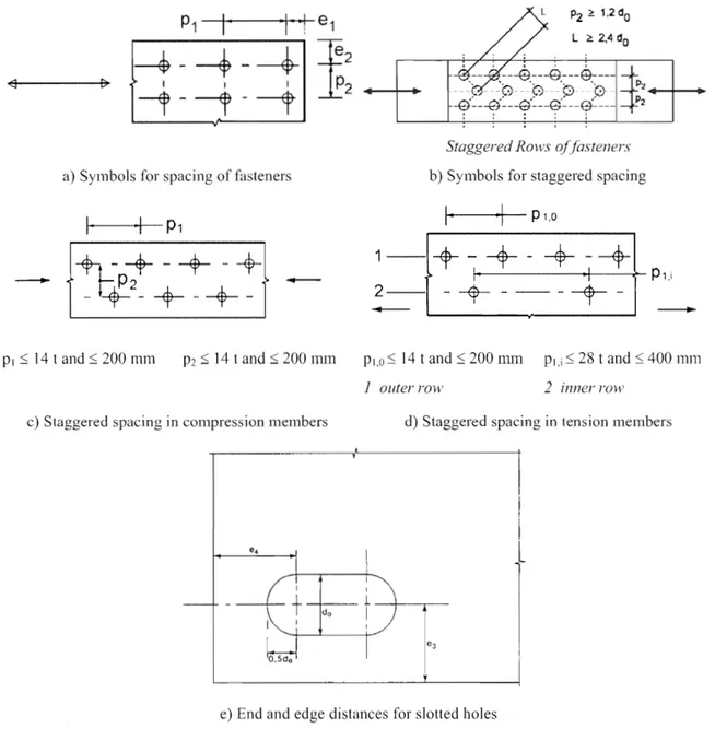
a) Symbols for spacing of fasteners
I
P1
1-.J~~--~i;;9---e---9---e--
.. 'i3 'i3 '~
'0
-tf~--?'~--?'~--~'~--~~---Staggered Rows affasteners
b) Symbols for stalggered spacing
1-[+ -.
jl-'---·+-1
+ -+
--+\
---O!--P1.i
2 -
-+
----r---
.
PI S; 14 t and 200 mm P2 S; 14 t and s; 200
mm
Pl,O s; 14 t and S; 200 nun P1.i 28 t and S; 400111111J outer rGH' 2 inner row
c) spacing in compression members d) Staggered spacing in tension members
e) End and edge distances for slotted holes
Figure 3.1: Symbols for end and edge distances and spacing of fasteners
3.6 Design resistance of individual fasteners
3.6.1
Bolts and rivets(1) The design resistance for an individual fastener subjected to shear and/or tension is given in Table 3.4. For preloaded bolts in accordance with 3.
calculations should be taken as:
the design preload, ,to be used in
NOTE: \Vhere the preload is not lIsed in design calculations see note to Table 3.2.
1)
for bolts with cut threads, such as anchor bolts or tie rods fabricated from round steel bars where the threads comply with EN 1090, the relevant values from Table 3.4 should be used. For bolts with cut threads where the threads do not comply with EN 1090 the relevant values from Table 3.4 should be multiplied by a factor of 0,85.
(4) The design shear resistance Fv,RcI given in Table 3.4 should only be used where the bolts are lIsed in
holes with nominal clearances not exceeding those for normal holes as specified in 1.2.7 Reference Standards: Group 7.
(5) MI2 and M14 bolts may also be used in 2 mm clearance holes provided that the design resistance of the bolt group based on bearing is less than or equal to~the design resistance of the bolt group based on bolt shear. In addition for class 5.8, 6.8, 8.8 and 10.9 bolts the design shear resistance
should be taken as 0,85 times the value given in Table 3.4. (6) fit bolts should be designed using the method for bolts in normal holes.
(7) The thread of a fit bolt should not be included in the shear plane.
(8) The length of the threaded portion of a fit bolt included in the bearing length should not exceed 1/3 of the thickness of the plate, see Figure 3.2.
(9) The hole tolerance used for fit bolts should be in accordance with 1.2.7 Reference Standards: Group 7.
(10) In single lap joints with only one bolt row, see figure 3.3, the bolts should be provided with washers under both the head and the nut. The design bearing resistance for each bolt should be limited to:
d t I )fM2
NOTE: Single rivets should not be used in single lap joints.
(11) In the case of class 8.8 or 10.9 bolts, hardened washers should be used for one bolt or one row of bolts.
... (3.2)
lap joints with only
(12) Where bolts or rivets transmitting load in shear and bearing pass through packing of total thickness tp
greater than one-third of the nominal diameter d, see Figure 3.4, the design shear resistance Fv •Rd
calculated as specified in Table 3.4, should be multiplying by a reduction factor
fJp
given by:9d
... (3.3)
(13) For double shear connections with packing on both sides of the splice, tp should be taken as the thickness of the thicker packing.
(lA) Riveted connections should be designed to transfer shear forces. If tension is present the design tensile
force should not exceed the design tension resistance Ft,Rd in Table 3.4.
(15) for grade S 235 steel the "as driven" value ofj~II' may be taken as 400 N/m1112.
(16) As a general rule, the grip length of a rivet should not exceed press riveting.
Figure 3.2: Threaded portion of the shank in the bearing length for fit bolts
Figure 3.3: Single lap joint with one row of bolts
I I I
+
+
+
+
+
+
+ +
Table 3.4: Design resistance for individual fasteners subjected to shear and/or
tension
Failure mode Bolts Rivets
Shear resistance per shear
rM2
- where the shear plane passes through the threaded portion of the bolt (A is the tensile stress area of the bolt
for classes 4.6~ 5.6 and 8.8:
ay = 0,6
- for classes 4.8, 5.8, 6.8 and 10.9:
ay 0,5
- where the shear plane passes through the un threaded portion of the bolt (A is the gross cross section of the boJt): Uy 0,6
rM2
tle<Ullllg resistance 1).2).
where ab is the smallest of ad ; or 1,0; in the direction of load transfer:
- for end bolts: ad = ; for inner bolts: ad
3d
operpendicular to the direction of load transfer:
~-for bolts: kl is the smallest of
do
-1,7,1,4
-1,7and- for inner bolts: kl is the smallest of
1,4
P2
-1,7
or 2,5do
Tension resistance
0,6
r
M2 rM2where k2 0,63 for countersunk bolt, otherwise k2 0,9.
Punching shear resistance / )1M2 No check needed
Combined shear and
tension ---~1,0
I)
3 }
The bearing resistance Fb,Rd for bolts
in oversized holes is 0,8 times the bearing resistance for bolts in normal holes.
- in slotted holes, where the longitudinal axis of the slotted hole is perpendicular to the direction of the force transfer, is 0,6 times the bearing resistance for bolts in round, normal holes,
For countersunk bolt:
- the bearing resistance Fb.Rd should be based on a thickness t equal to the thickness of the connected plate minus half the depth of the countersinking.
for the determination of the tension resistance the angle and depth of countersinking should conform with 1.2.4 Reference Standards: Group 4, otherwise the tension resistance should be adjusted accordingly.
When the load on a bolt is not parallel to the the bearing resistance may be verified separately for the bolt load com onents )arallel and normal to the end.
3.6.2 Injection bolts
3.6.2.1 General
(1) Injection bolts may be used as an alternative to ordinary bo1ts and rivets for category A, Band C connections specified in 3.4.
(2) fabrication and erection details for injection bolts are given in ] .2.7 Reference Standards: Group 7.
3.6.2.2 Design resistance
(1) The design method in 3.6.2.2(2) to 3.6.2.2(6) should be used for connections with injection bolts of class 8.8 or J 0.9. BoH assemblies should conform with the requirements given in 1.2.4 Reference Standards: Group 4, but see 3.6.2.2(3) for when pre loaded bo1ts are used.
(2) The ultimate shear load of any bolt in a A connection should not exceed the smaller of the following: the design shear resistance ~ of the bolt or a group of bolts as obtained ~ from 3.6 and the design bearing resistance of the resin as obtained from 3.6.2.2(5).
(3) Preloaded injection bolts should be Llsed for category Band C comlections, for which preloaded bolt assemblies in accordance with 3.1.2(1) should be used.
(4) The design serviceability shear load of any bolt in a category B connection and the design ultimate shear load of any bolt in a category C connection should not exceed the design slip resistance of the bolt as obtained from 3.9 at the relevant limit state plus the design resistance of the resin as obtained from 3.6.2.2(5) at the relevant limit state. In addition the design ultimate shear load of a bolt in a category Bore connection should not exceed either the design shear resistance of the bolt as obtained from 3.6, nor the bearing resistance of the bolt as obtained 1'ro1113.6 and 3.7.
(5) The bearing resistance of the resin, may be determined according to the following equation:
F b,Rd.rcsin
1:\44
where:
1S the strength of an injection bolt
/1 is a coefficient depending of the thickness ratio of the connected plates as given in Table 3.5 and figure 3.5
is the bearing strength of the resm to be determined according to the 1.2.7 Reference Standards: Group 7.
tlHl',;in is the effective bearing thickness of the resin, in Table 3.5
kl 1S 1,0 for serviceability limit state (long duration) is 1,2 tor ultimate limit state
k, is taken as 1,0 for holes with normal clearances or (1,0 0,1 111), for oversized holes
!I1 is the difference (in 111m) between the normal and oversized hole dimensions. In the case of
short slotted holes as specified in 1.2.7 Reference Standards: Group 7, 111 = 0, 5 . (the difference (in 111m) between the hole length and width).
(6) When calculating the resistance of a bolt with a clamping length exceeding 3d, a value of not more than 3d should be taken to determine the effective bearing thickness (see figure 3.6).
~
~t'
t1 1,33 1,0 t2 °1 1.0 °2 2.0Figure 3.5: Factor
B as a function of the thickness ratio of the connected plates
Table 3.5: Values of 13 and
tb,resin2,0 1,0 t]/12 2,0 1,0 jJ 1,0 1,66 - 0,33 (tl / 1,33 2 t2 1.5 d tl <
1,5
d t1 S:. dFigure 3.6: Limiting effective length for long injection bolts
3.7 Group of fasteners
(l) The design resistance of a group of fasteners may be taken as the sum of the design bearing resistances of the individual fasteners provided that the shear resistance }~"Rd of each individual fastener is greater 1han or equal to the design bearing resistance Fb. Rd . Otherwise the design resistance of a group of fasteners should be taken as the number of fasteners multiplied by the sma]]est design resistance of any of the individual fasteners.
3.8 Long joints
(l) \\1here the distance Lj between the centres of the end fasteners in a joint, measured in the direction of force transfer Figure 3.7), is more than 15 d, the design shear resistance F\,.Rd of all the fasteners calculated according to Table 3.4 should be reduced by multiplying it by a reduction factor
flu,
givenJ -
-15d
but ],0 and
ftLf
2: 0,75(2) The provision in 3.8(1) does not apply where there is a uniform distribution of force transfer over the length of the joint, e.g. the transfer of shear force between the web and the flange of a section.
L'
I~ J
-j
s----
FLj LJ
l~~~--~~·~!
I-
-,
F....-}~:~~~!
ln~:
nt.!llllnlc:!;i;h~~U ~o:t:H :t::tm~:I: s~
FFigure 3.7: Long joints
3.9 Slip-resistant connections using 8.8 or 10.9 bolts
3.9.1 Design Slip resistance
(l) The design slip resistance of a pre10aded class 8.8 or 10.9 bolt should be taken as:
~ ... (3.6a)@11
r
... (3.6b)@11
where:
ks is given in Table 3.6
n is the number of the friction planes @11
J1 is the slip factor obtained either specific tests for the friction surface in accordance with 1.2.7 Reference Standards: Group 7 or when relevant as given in Table 3.7.
(2) For class 8.8 and 10.9 bolts conforming with 1.2.4 Reference Standards: Group 4, with controlled tightening in conformity with 1.2.7 Reference Standards: Group 7, the preloading force Fp,c to be used in equation (3.6) should be taken as:
0,7fllb ... (3.7)
Table 3.6: Values of
ks
Description
k,Bolts in normal holes. 1,0
Bolts 111 either oversized holes or short slotted holes with the axis of the slot
0,85 perpendicular to the direction of load transfer.
Bolts in long slotted holes with the axis of the slot perpendicular to the direction of load transfer.
Bolts in short slotted holes with the axis of the slot parallel to the direction of load
0,76 transfer.
Bolts in long slotted holes with the axis of the slot parallel to the direction of load
0,63 transfer.
Table 3.7: Slip factor,
1-1,
for pre-loaded bolts
Class of friction surfaces 1.2.7 Reference Slip factor II Standard: Group 7)
A 0,5
B 0,4
C 0,3
D 0,2
NOTE 1: The requirements for testing and inspection are given in 1.2.7 Reference Standards: Group 7.
NOTE 2: The classification of any other surface treatment should be based on test specimens representative of the surfaces used in the structure using the procedure set out in 1.2.7 Reference Standards: Group 7.
NOTE 3: The definitions of the class of friction surface are given in 1.2.7 Reference Standards: Group 7.
NOTE 4: With painted surface treatments a loss of pre-load may occur over time.
3.9.2 Combined tension and shear
(1) If a slip-resistant connection is subjected to an applied tensile force, or in addition to the shear force, Fv •Ed or tending to produce slip, the design slip resistance per bolt should be taken as follows:
for a category B connection:
)
... (3.8a)Y,\'!J,ser
for a category C connection: ... (3.8b)
(2) If, in a moment connection, a contact force on the compression side counterbalances the applied tensile force no reduction in slip resistance is required.
3.9.3 Hybrid connections
(1) As an exception to 2.4(3) , preloaded class 8.8 and 10.9 bolts in connections designed as slip-resistant at the ultimate limit state (Category C in 3.4) may be assumed to share load with welds, provided that the final tightenjng ofthe bolts is canied out after the welding is complete.
3.10 Deductions for fastener holes
3.10.1 General
3.10.2 Design for block tearing
(1) Block tearing consists of failure in shear at the row of bolts along the shear face of the hole group accompanied by tensile rupture along the line of bolt boles on the tension face of the bolt group. Figure 3.8 shows block tearing.
(2) For a symmetric bolt group subject to concentric loading the design block tearing resistance, IS given by:
IYM2
+
(lI
';3)lv
where:
A nl is net area subjected to tension; Am IS net area subjected to shear.
... (3.9)
(3) For a bolt group subject to eccentric loading the design block shear tearing resistance is by:
J
r . r - - - r -2
:-(11 AI1\'
1 small tension force 2 large shear 3 small shearforce 4 large tensionforce
Figure 3.8: Block tearing
3.10.3 Angles connected by one leg and other unsymmetrically connected members in tension (1) The eccentricity in joints, see 2.7(1), and the effects of the spacing and
should be taken into account in determining the design resistance of: unsymmetrical members;
distances of the bolts,
symmetrical members that are connected unsYIIDlletrically, such as angles connected by one leg.
(2) A single angJe in tension connected by a row of bolts in one see Figure 3.9, may be treated as concentrically loaded over an effective net section for which the design ultimate resistance should be determined as follows:
with
1
bolt: 11)with 2 bolts: ... (3.12)
with 3 or more bolts: Nu.Rd ... (3.13)
YM2
where:
fJ2 and fJ3 are reduction IJlctors dependent on the pitch PI as given in Table 3.8. For intermediate values of PI the value of fJ may be determined by linear interpolation;
Ancl is the net area of the angle. For an unequal-leg connected by its smaJler leg, And should
be taken as equal to the net section area of an equivalent equal-leg angle of size equal to that of the smaller leg.
Table 3.8: Reduction factors
P2
and
P3
Pitch PI do 5,0 do 2 bolts fJ2 0,4 0,7 3 bolts or more 0,5 0,7 a) 1 bolt b) 2 bolts c) 3 bolts (a) \...6 1