67
6
6
In
I
nt
te
er
rn
n
al
a
l
a
ar
rc
ch
h
i
i
te
t
ec
ct
tu
u
re
r
e
f
fo
o
r
r
t
t
h
h
e
e
ne
n
ew
w
BT
B
T-
-D
D
e
e
m
m
o
o
d
d
u
u
l
l
a
a
t
t
o
o
r
r
Here below, a description of a possible solution is given in order to implement the several functions for the new Bluetooth demodulator. As hinted in the previous chapter, this implementation is composed of two principal architectures: the two EDR Demodulation blocks and the Timing Recovery scheme; both supported by a Vector Product module.
6.1 New BT- Demodulator architectures
Demodulation may be implemented in digital signal processing software (DSP), analog circuit, or digital hardware. A digital signal processing approach is flexible and adaptable to fabrication technologies and power supply voltages. However this approach requires large power consumption and size. In contrast to the DSP approach, an analog hardware approach is not readily adaptable and is not easy to manufacture due to its susceptibility to analog component deviation. Digital hardware offers ease of manufacturing, adaptability, low power consumption and small size. However digital hardware is not flexible as the DSP implementation. This can be considered a small price to pay compared to digital hardware benefits; finally, digital hardware represents the suitable solution for the scope.
In this chapter, two different architecture, for the π/4-DQPSK and the 8DPSK modulations will be presented separately. These architectures are able to demodulate the signal without getting an absolute value of the symbol phase, but only the region of the constellation points, in which the received data are located. First, in order to achieve this goal, it is necessary to implement a module that elaborates two consecutive received symbols and yields information according to
Chapter 6 Internal architecture for the new BT-Demodulator
68 their phase difference. As introduced in the previous chapter, the Vector Product block is already implemented on the GFSK-chip and may be reused for the EDR demodulator. Or rather, it does not only support the timing recovery block, but plays an important role in the demodulation part. Now, some relations are given to clarify its functionality. After the SRRC filtering, the complex symbols sampled at FC frequency value (13MHz or 6.5MHz), are sent to the vector product block, as shown in Figure 6.1. They can be expressed as follows:
K C jΦ K K K k/F t S[k] I jQ A e s(t) = = = + = (6.1) IK = AKcos
( )
ΦK ; QK = AKsin( )
ΦK (6.2) Maintaining the old notation used with the previous receiver, the equations referred to the vector product calculations are given:1 -K K 1 -K K ) Vcos(k =I ⋅I +Q ⋅Q (6.3) 1 -K K 1 -K K ) Vsin(k =−I ⋅Q +Q ⋅I (6.4)
These relations are equal to:
(
K K-1)
K K-1(
K)
1 -K K 1 -K K 1 -K K 1 -K K 1 -K K cos cos sin sin cos cos ) Vcos( ∆Φ = Φ − Φ = = Φ Φ + Φ Φ = A A A A A A A A k (6.5)(
K K-1)
K K-1(
K)
1 -K K K 1 -K 1 -K K 1 -K K 1 -K K sin sin sin cos sin cos ) Vsin( ∆Φ = Φ − Φ = = Φ Φ + Φ Φ − = A A A A A A A A k (6.6)Thus, the difference phase value ∆ΦK =ΦK −ΦK−1 is directly obtain, but only in term of sin(•) and cos(•) projections. At this point, it is easier to understand in which region the transmitted data is located, without calculating the exact values of the symbols phase involved. This algorithm is valid for both the EDR demodulation, according with the different regions number of the constellation points.
Chapter 6 Internal architecture for the new BT-Demodulator
69
π/4-DQPSK demodulation: phase evaluation
Referring to the π/4-DQPSK specifications, the possible transmitted data phase may belong to the values:
{
±π /4; ±3π /4}
. These are exactly the phase values that bisect the four quadrants of the constellation points, as shown in the following figure: 01 11 10 00 ∆ΦK Vector Product block Vcos(13) Vsin(13) N bits ROM MSB MSB bit2K-1 bit2K s[k] s[k-1] 22 x 2 Quadrant evaluationFigure 6.1 – Decision zones and simple Hardware implementation.
In this way, it is sufficient to use a Quadrant Evaluator that checks simply the signs of both the vector product results and decides in which region the phase difference is located. Using a sampling frequency of 13 MHz, it should be clarified that the vector product algorithms are performed for each sampled data separate by a T period, this means that the K coefficient is equal to K = 13. Therefore the Vcos(13) and the Vsin(13) value are involved. A simple hardware implementation is given below in order to achieve the demodulated 2-bits data.
∆Φk b2k-1 b2k Vcos(13) Vsin(13)
π/4 0 0 > 0 0 > 0 0
3π/4 0 1 < 0 1 > 0 0
-3π/4 1 1 < 0 1 < 0 1
-π/4 1 0 > 0 0 < 0 1
Table 6.1 − π/4-DQPSK: de-mapping functionality.
As known, it is sufficient to consider only the MSB of the bits value to check its sign. Hence, the four possible combinations are investigated by a ROM with a very small size (22 · 2-bits), that follows the specifications shown in Table 6.1.
Chapter 6 Internal architecture for the new BT-Demodulator
70
8DPSK demodulation: phase evaluations
In this case, the situation is more complex because eight different symbol phases may be transmitted:
{
0, ±π /4, ±π /2, ±3π /4 ,π}
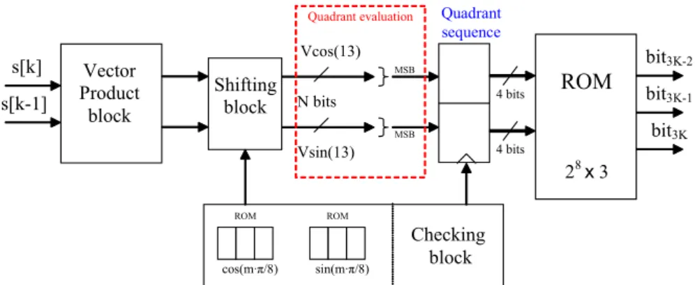
. They belong to the same constellation points related to the π/4-DQPSK case, but now eight equiprobable regions can be identified, as pointed out in the left side of Figure 6.2. Each of them is π/4 radiant wide, which is half value in comparison of the π/4-DQPSK case. Thus a direct quadrant evaluator can not be properly used and now it is necessary to implement a more complex algorithm that elaborates the symbol phase through phase rotations, in order to may still use the quadrant evaluation.000 ∆ΦK Vcos(13) & Vsin(13) + π/8 3 cycles Quadrant evaluation Storing sequence Data Demod. bit3K-2 bit3K-1 bit3K 001 011 010 110 111 101 100 A B C D E F G H I J K L M N O P
Figure 6.2 – Decision zones for 8DPSK and demodulation algorithm flowchart.
Firstly an evaluation is made in order to know in which quadrant the received symbol is. Then, three phase shifts of π/8 are made and the related quadrant is evaluated constantly. In every step, the relative output 2-bits are stored in a buffer sequence that is investigated through a ROM. In fact, four quadrant evaluations are stored and thus the algorithm is able to recognise in which of the sixteen constellation slices the received symbol is located. In this way, the phase difference ∆ΦK is measured with a maximum uncertainly of π/8, that is sufficient for a correct demodulation. Referring to the three rotations, always using a π/8 step, some trigonometric relations are given in order to clarify the related hardware implementation.
Chapter 6 Internal architecture for the new BT-Demodulator 71 Let: = = ) 8 / sin( ) 8 / cos( π π b a
; the following equations are valid:
) sin( ) cos( ) 8 / sin( ) sin( ) 8 / cos( ) cos( ) 8 / cos( α α π α π α π α ⋅ − ⋅ = = − = + b a (6.7) ) sin( ) cos( ) 8 / sin( ) cos( ) 8 / cos( ) sin( ) 8 / sin( α α π α π α π α ⋅ + ⋅ = = + = + a b (6.8)
It should be clarified that real values, such as cos(π/8) or sin(π/8), must be binary codified in order to be processed into digital circuits. For this scope, some approximations are required and the resulting values could be surely affected by errors. In this case, the real values of the three phase rotations have been computed using an optimization algorithm (implemented by a Matlab code) and codified respecting the minimum rounding error. Thus, the integer coefficients are stored inside one memory (ROM) and are used within the Shifting block as multiplier values. After every step, the sign of the shifted value is checked and the output bits sequence of the quadrant evaluator is memorized into two registers. At the end, as shown in the figure below, a ROM codifies the two quadrant sequences in order to perform the 3-bits demodulated data. In theory the resulting ROM size should be equal to 28· 3-bits, due to the two quadrant sequences are each composed of four bits; instead, only sixteen sequences related to every sector of the constellation points are significant. Therefore a smaller ROM size could be achieved. Vector Product block Vcos(13) Vsin(13) N bits ROM MSB MSB bit3K-2 bit3K-1 s[k] s[k-1] 28 x 3 Shifting block ROM ROM cos(m·π/8) sin(m·π/8) Checking block
Quadrant evaluation Quadrant
sequence
bit3K 4 bits
4 bits
Chapter 6 Internal architecture for the new BT-Demodulator
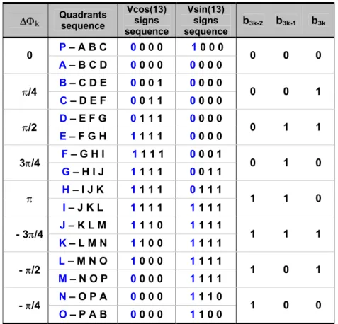
72 At this point, all the sixteen resulting sequences are codified into the output 3-bits, as summarized in the table below.
∆Φk Quadrants sequence Vcos(13) signs sequence Vsin(13) signs sequence b3k-2 b3k-1 b3k P – A B C 0 0 0 0 1 0 0 0 0 A – B C D 0 0 0 0 0 0 0 0 0 0 0 B – C D E 0 0 0 1 0 0 0 0 π/4 C – D E F 0 0 1 1 0 0 0 0 0 0 1 D – E F G 0 1 1 1 0 0 0 0 π/2 E – F G H 1 1 1 1 0 0 0 0 0 1 1 F – G H I 1 1 1 1 0 0 0 1 3π/4 G – H I J 1 1 1 1 0 0 1 1 0 1 0 H – I J K 1 1 1 1 0 1 1 1 π I – J K L 1 1 1 1 1 1 1 1 1 1 0 J – K L M 1 1 1 0 1 1 1 1 - 3π/4 K – L M N 1 1 0 0 1 1 1 1 1 1 1 L – M N O 1 0 0 0 1 1 1 1 - π/2 M – N O P 0 0 0 0 1 1 1 1 1 0 1 N – O P A 0 0 0 0 1 1 1 0 - π/4 O – P A B 0 0 0 0 1 1 0 0 1 0 0
Table 6.2 − 8-DQPSK: de-mapping’s functionality.
This scheme follows a first approach to the 8DPSK demodulation algorithm and the three consecutive phase evaluations may result redundant. Surely, this method needs some improvements that will be investigated during future works.
6.2 Timing recovery architectures
Timing recovery is one of the most critical demodulator functions. Normally, an algorithm which can extract the timing information from the sampled data stream is required. Timing recovery algorithm can be classified into two categories according to the data dependency [7]:
Chapter 6 Internal architecture for the new BT-Demodulator
73 Class 1: Decision Directed (DD) or Data-Aided (DA)
Class2: Non-data-Aided (NDA)
The estimation algorithm DD or DA takes place when the data stream is checked in comparison with a known data sequence, established by the specifications. Otherwise, the estimation is NDA. In analog receivers, NDA timing recovery is usually implemented by a feed-back loop that adjusts the phase of the local oscillator, or by a feed-back arrangement that regenerates a timing signal from the incoming signal.
As has been hinted in the previous chapters, a hybrid timing recovery for the two Bluetooth standards has been chosen. It implements a digital algorithm that checks the digitised data stream and is able to control the sampling instant of the A/D converter. In this case, a Synchronous Sequence is transmitted for both of the two Bluetooth standards: inside the GFSK Access Code and through the specific Synchronous Sequence according with the EDR modulations.
Now, referring only to the EDR case; this Bluetooth specifications suggest a known sequence made up of a reference symbol (with arbitrary phase) followed by 10 DPSK symbols. The phase changes between the DPSK symbols shall be:
{
}
{
3 /4 -3 /4 3 /4 -3 /4 3 /4 -3 /4 -3 /4 3 /4 3 /4 3 /4}
10 9 8 7 6 5 4 3 2 1 π π π π π π π π π π = ∆Φ ∆Φ ∆Φ ∆Φ ∆Φ ∆Φ ∆Φ ∆Φ ∆Φ ∆Φ Guard Time5µsec Ref Symb. S1 S2 S3 S4 S5 S6 S7 S8 S9 S10 MED Payload
∆Φ1 is the phase change between the reference symbol and the first DPSK symbol S1 ; while ∆ΦK is the phase change between the k-1th (SK-1) and the kth symbols (SK). The synchronization sequence may be generated using modulator by pre-pending the Payload data.
For π/4-DQPSK, the pre-pended bits are:
{
01,11,01,11,01,11,11,01,01,01}
For 8DPSK, the bit sequence used to generate the synchronous sequence is:
Chapter 6 Internal architecture for the new BT-Demodulator
74 Since the symbol timing algorithm checks the information in term of phase and the phase changes between the symbols are the same for both the new modulation types; then only one algorithm can be applied for both cases. At this aim on instance of the In-phase and the In-quadrature modulated signals referred to the EDR Synchronous Sequence are shown below. Consequently, the resulting Vcos(13) and Vsin(13) signals are reported in order to understand the timing recovery functionality.
Figure 6.4 – a) In-phase IK signal; and b) In-quadrature QK signal, both related to the
Chapter 6 Internal architecture for the new BT-Demodulator
75
Figure 6.5 – Vcos(13) and Vsin(13) signals, related to the Synchronous Sequence.
As hinted before, the GFSK timing recovery uses an algorithm based on the two vector product values. Since the transmission of a binary 1 gives rise to a positive frequency deviation from the nominal carrier frequency; and a binary 0 gives rise to a negative frequency deviation; then the resulting transmitted phase differences are positive (∆ΦK > 0) when a binary 1 is transmitted and negative (∆ΦK < 0), otherwise. In this way, the algorithm checks the zero crossing points (∆ΦK = 0) of the Vcos(13) signal, in order to achieve the data stream frequency equal to 1 MHz. It should be clarified this GFSK algorithm is still used for the pre-pending GFSK part. Instead for the EDR case, a new time recovery algorithm needs to be implemented. Now, both of the vector product signals, carrying the demodulated data information are computed. Or rather, an algorithm based directly on the demodulated data stream is implemented. This method compares both the data stream with the two known Sync.Sequences, composed by 20 bits for the
π/4-Chapter 6 Internal architecture for the new BT-Demodulator
76 DQPSK or 30 bits for the 8DPSK. Before to be sampled in order to obtain the final demodulated data, the vector product signals are directly demodulated. Thus, every TC period a different demodulated data stream is achieved and the comparison respect to the Sync.Sequence is made bit-per-bit. The number of the equal bits is calculated and when it exceeds a threshold level, the related Sync.Sequence is recognized. In this way, the algorithm is able to select the correct instant among the thirteen possible points inside every T period. One time that the Sync.Sequence is ended, the timing recovery block establishes the sampling frequency and the instant in which the future sampling starts. As shown in the following figures, when the Sync.Sequence is recognized, a peak within the Equal-bits sum occurs. Afterwards, the number of instants NTR during which the peak exceeds the fixed threshold are kept in count. Finally, the sampling functionality starts with a time delay equal to T − NTR ⋅TC
2 seconds after the last still recognized instant. It can be also considered as a T period after the central instant of the peaks.
Figure 6.6 – Equal-bits sum for the π/4-DQPSK and the 8DPSK timing recovery algorithms.
In this way, two peaks are obtained and can be used both, or singly for the internal calculations of the timing recovery algorithm. Furthermore, depending on the
Chapter 6 Internal architecture for the new BT-Demodulator
77 threshold and the used equal-bits sum, the NTR value could not be the same for both cases. However, the peaks are concentric and the higher value occurs in the same time. But, as known, the sampling block works with a frequency equal to 13 MHz and may introduce some time approximation errors. In this way, when the ideal centre of the peak is not equal to any sampling period, the algorithm must make a choice between the two nearest sampled instants. Thus, an algorithm that involves both the Equal-bits sum could be implemented in order to easily select the correct instant.