111
6. Polymer Stabilized CdSe Nanocrystals
Inorganic semiconductor nanocrystals, also known as quantum dots (QDs), have been extensively studied over the past decades because of their unique size dependent optical properties,1 which differ significantly from those of bulk materials. In addition to possessing size-tunable electronic and optical properties resulting from quantum confinement,2 QDs offer high resistance to photo−bleaching, thus making them attractive components of hybrid materials for optoelectronic3,4 and in vivo bio−sensing applications.5
QDs are efficient light absorbers in the spectral region covered by the sunlight and materials based on QDs hold considerable promise for numerous applications in the field of electronics and photonics. One important example is their possible role, in association with conjugated polymers, as components of active photovoltaic (PV) layers for hybrid p-n (donor−acceptor) type solid state solar cells.6
Figure 6.0 schematically illustrates the charge transfer process in a donor-acceptor photoactive hybrid system based on semiconductor nanoparticles and polymer.7 Hybrid photo active layers have been considered as a new alternative in PV technology due to their flexibility, light weight, low-cost fabrication, easy integration into a wide variety of devices, and tunable properties typical of organic (polymeric) materials. Similarly to organic PV systems based on polymer/fullerene mixtures, a composite of conjugated polymer and semiconductor nanoparticles may act as a donor-acceptor system.
Until now the maximum achieved performance of both hybrid and purely organic devices is still low compared to the inorganic solar cells.8 Several causes such as poor charge transport efficiency, limited exciton diffusion length, weak absorption coefficients and inadequate nanoscale morphology may account for the low efficiencies of polymer based PV devices.9 To overcome the limitation of the typically short exciton diffusion length, blending of either two organic semiconductors or organic and inorganic semiconductors to generate the so-called bulk heterojunction (BHJ) are investigated. Different strategies for achieving such interpenetrating networks of donor (electron donating and hole transporting) and acceptor (electron accepting and transporting) materials have been pursued for increasing the donor/acceptor interfacial area of orders of magnitude and reducing the domain size of the hybrid heterogeneous systems to few tens of nanometers.10
112
Figure 6.0 Schematic representation of the charge transfer in hybrid composites of inorganic
semiconductor nanoparticles and polymer on the example of the system CdSe/P3HT.
Unfortunately, while the working principle of hybrid solar cells was already demonstrated,6 the efficiency achieved so far is still below 5%.11 Current aims in this research field are to understand and improve the physics and chemistry of elementary steps such as the charge transfer at the interface within the active PV layers and charge transport within percolating semiconducting domains in order to improve the overall efficiency of hybrid solar cells.
Because, the inorganic semiconductors can be manufactured as nanoparticles by using colloidal synthesis routes,12 control of the particle size offers additional possibilities both for achieving the desired BHJ morphology and to adjust the absorption properties to cover the entire sunlight spectrum. For the preparation and stabilization of inorganic semiconductor nanocrystals, many methods have been applied so far. One of them involves using a polymer stabilizer having surface-specific functional groups.13 For example, a copolymer consisting of poly(ethylene glycol) and poly(ethylene imine) blocks has been used as effective stabilizer for the synthesis of CdS nanoparticles.14 In this and similar methods, control of particle size and morphology often requires accurate adjustment of such parameters as polymer concentration and type of solvent.
When the band gap of the QD within a conjugated polymer /nanocomposites matches the visible spectral range both the conjugated polymer and the QD contribute to the overall light absorption, resulting in an increased efficiency of optical excitation. Furthermore, nanocomposites materials in which the inorganic nanocrystal has a higher electron affinity than the conjugated polymers matrix are efficient in the separation of charges, and consequently are efficient absorbers of solar radiation.15 Finally, combining electron transporting QDs with a good hole-transporting polymer, such as poly(3-hexylthiophene) (P3HT) enables the good interparticle electron transport characteristics of inorganic semiconductors to be exploited, while adding the solution processibility typically of polymeric materials.
113
As a further variation of the conjugated polymer/QD combination, consisting in the association of CNTs with hybrid polymer/QD systems, may result in additional useful properties provided by the unique morphological and electrical features of CNTs such as easier formation of percolating electroconducting structures generated by overlapping CNTs.16, 17 Although the distortion of a CNT results in a decrease in its conductivity due to the bending induced electron-transport barrier,18 semiconducting polymers and QDs can be conjugated with carbon nanotubes to create heterojunctions. The development of CNT/QD heterojunctions has become an active field of research also as the result of recent developments in chemical modification of CNTs. Because of their chemical inertness, the modification of CNTs was originally carried out by noncovalent functionalization.19 Covalent chemical modification20 is more controlled and stable but induces modifications (often undesired) in the graphitic lattice structure of the CNTs. The first direct covalent functionalization method was based on the acid oxidation of CNTs,21 which results in the introduction of carboxyl groups at the tips and other outer surface sites with high defect density. Additional CNT functionalization reactions included fluorination,22 electrophilic addition of chloroform,23 esterification,24 grafting with synthetic and biological polymers.25, 26
In this chapter, the results of the investigations on three different systems based on the CdSe/P3HT hybrid incorporated within the three different architectures and compositions shown in schemes 6.1, 6.2 and 6.3 are presented. In particular, controlled nucleation and growth or simply localized stabilization of CdSe QDs was pursued by:
a) use of poly(acrylonitrile) grafted on CNT as a templating system; b) use of a P3HT-b-PAN as a templating polymer and colloidal stabilizer; c) use of phosphonic acid terminated rr-P3HT as stabilizer.
6.1 Controlled growth of CdSe Nanoparticles onto MWNT-g-PAN
The procedure for the preparation of nanostructured MWNT-g-PAN/CdSe hybrids is depicted in scheme 6.1. The CdSe nanoparticles were chemically grown in the presence of MWNT-g-PAN, which was expected to act as a preferential locus for the controlled precipitation of colloidal CdSe from the aqueous solution. MWNT-g-PAN was synthesized by “grafting from” polymerization of acrylonitrile in the presence of MWNT-RAFT as described in chapter 5. This strategy is potentially interesting for the fabrication of hybrid conjugates of CNTs with different inorganic nanoparticles dispersed in aqueous or organic solvents. According to the literature,27 the polyacrylonitrile chain can be an effective polymeric stabilizer for CdSe nanoparticles because Cd2+ readily undergoes complexation in the presence of CN groups. The CdSe nanoparticles in-situ
114
synthesized in the presence of MWNT-g-PAN where then characterized by FT-IR, TEM, AFM, SEM, and UV-VIS techniques.
6.1.1 Synthetic procedures
A 0.1 M Na2SeSO3 aqueous stock solution was prepared by stirring Se powder (0.3948 g, 5
mmol) and Na2SO3 (1.2604 g, 10 mmol) in 50 mL deionized water under nitrogen atmosphere at 60
°C for about 4 hr. Deionized water had been previously deoxidized by passing N2 under vigorous
stirring.
Separately, an aqueous stock solution of CdSO4 (0.1 M) was prepared by dissolving
CdSO4.2.67H2O (1.28 g, 1 mmol) in 50 mL of deionized water, and deoxygenated by purging with
nitrogen for 30 min.
MWNT-g-PAN (50 mg) (4) was then dispersed in 80 mL DMF in a three-necked round bottom flask by means of a magnetic stirrer and deoxygenated by repeated vacuum cycles followed by filling with nitrogen. A deoxygenated CdSO4 solution (0.01 M, 30 mL) was transferred into the
mixture and deoxygenated 0.1 M aqueous NaOH solution was added until pH=8. Then a stoichiometric ratio of Na2SeSO3 as aqueous solutions (0.01 M, 30 mL) was injected into the
mixture under vigorous stirring, which was continued for 5 hr under nitrogen atmosphere in the dark. The resultant red colored mixture containing a theoretical 50 mg MWNT-g-PAN and 55 mg CdSe was collected on a 0.2 µm PTFE membrane filter and repeatedly washed with deionized water to remove any unreacted salts and soluble side products. To remove any residual Cd and Se precursor and free nanosized CdSe, the resultant CdSe /MWNT mixture (5) were dispersed in DMF and sonicated for 15 min in a sonicating bath, then collected again on a membrane filter and repeatedly washed on the filter with small DMF portions. The mixture was dried under vacuum at 50 °C overnight to yield 74.46 mg of product (Scheme 6.1).
6.1.2 Results and discussion
In chapter 5 it was shown that the “grafting from” RAFT polymerization technique allows to obtain MWNT-g-PAN starting from MWNT modified with a suitable RAFT agent. The improved dispersibility of the MWNT in DMF upon grafting of PAN chains makes its characterization easier, while the general “grafting from” polymerization method allows the unique properties of nanotubes to be modified according to the type, surface density, and molecular weight of the grafted polymer chains.
115
The synthesis of CdSe was performed by the conventional procedure consisting in the controlled reductive precipitation of CdSe from a mixed solution of CdSO4 and Na2SeSO3 which, in
this modified method, was carried out in the presence of MWNT-g-PAN.
COCH2CH2OC C O O CH3 CH3 S C S NC CN COCH2CH2OC C O O CH3 CH3 S C S NC CN Cd2+ SeSO3 2-CdSe 4 5
Scheme 6.1 CdSe NPs growth on modified MWNT-g-PAN
The reaction was performed starting from an equimolar amount of Na2SeSO3 and CdSO4
precursors (the former prepared using a twofold molar excess of Na2SO3 vs Se). The calculated
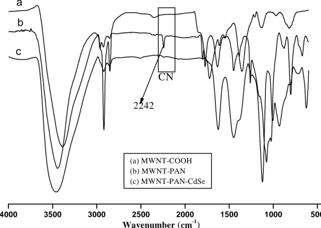
weight of the resulting CdSe was equal to the weighted amount of MWNT-g-PAN. The final product, MWNT-g-PAN/CdSe was characterized by FT-IR and UV-VIS spectroscopy and by SEM, TEM and AFM microscopy. The FTIR spectrum recorded from sample in KBr pellet at a 1% concentration is shown in figure 6.1a. The absorption centered on 1720 cm−1 is the envelope of multiple carboxyl, carboxy ester and anhydride stretching vibrations and the broad band at 3444 cm
-1
is attributable to the -OH stretching vibration from both absorbed water and the unmodified residual COOH groups resulting from the initial acid oxidation. The peak at 1580 cm−1 is due to the C=C stretching vibrational modes from the graphene structure of carbon nanotubes. The CN stretching absorption peaking at 2242 cm-1 from the poly(acrylonitrile) chains grafted on the sidewall of MWNTs (Figure 6.1b) has almost disappeared after hybridization with CdSe nanocrystals (Figure 6.1c). This may be the result of specific adsorption of MWNT grafted PAN chains onto CdSe favored by the coordination of its CN groups onto the unsaturated Cd2+ ions at the CdSe nanoparticles surface, as reported in the literature.28 Several examples are reported in the literature,28, 29in which the spectra of various inorganic nanoparticles modified with
116
polyacrylonitrile-block-poly(ethylene glycol)-block-polyacrylonitrile and CNT/PEI (polyethyleneimine) containing CN groups were investigated and showed similar reduction of the intensity of the CN stretching absorption band.
4000 3500 3000 2500 2000 1500 1000 500 Wavenumber
(
cm-1)
(a) MWNT-COOH (b) MWNT-PAN (c) MWNT-PAN-CdSea
b
c
CN
2242
Figure 6.1 The FT-IR spectra of (a) MWNT-COOH (b) MWNT-g-PAN (c) CdSe/MWNT-g-PAN
The CdSe/MWNT-g-PAN hybrid was characterized by scanning electron microscopy (SEM). The samples were prepared by casting a drop of diluted mixture in DMF onto a copper strip and evaporation under vacuum at ambient temperature for 1 hr. In figure 6.2a, the surface morphology of MWNT-g-PAN is far from that expected for “naked” MWNTs, indicative of significant polymer grafting on the nanotube surface. As already discussed in chapter 5, according to the TGA results the polymer on the MWNTs surface is about 45 % by weight, a relatively small fraction that is apparently sufficient for modifying drastically the surface morphology of the MWNTs. After hybridization with the CdSe nanocrystals the morphology is characterized by a finer grained appearance (Figure 6.2b). From the SEM micrographs the presence of a fraction of CdSe as “free” nanocrystals co-precipitated with the CdSe nanoparticles enclosed into MWNT-g-PAN could not be excluded.29
117
a
b
Figure 6.2 SEM images of MWNT-g-PAN (a), and CdSe/ MWNT-g-PAN (b)
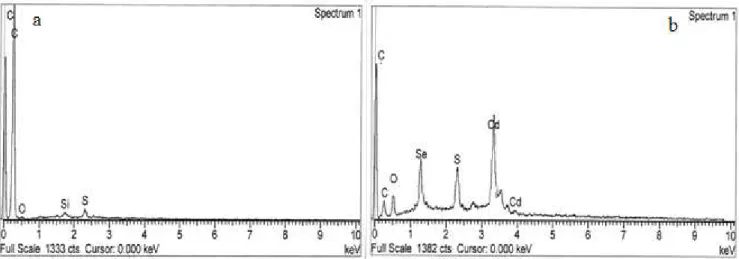
The elemental analysis performed by energy dispersive spectroscopy (EDS) with the SEM instrument gave results that are shown by the two representative spectra of figure 6.3. In the spectrum of MWNT-g-PAN (Figure 6.3a) only a strong peak for C and very weak ones for S and O are visible (Si is the contamination from the instrument and N overlaps with the C signal), originated from the MWNT carbon and the residual sulfur-containing fragment from the RAFT agent. After hybridization with CdSe the EDS spectrum of figure 6.3b was recorded in which, in addition to the expected peaks of Cd and Se due to the presence of CdSe nanocrystals and that of C (weaker than for MWNT-g-PAN), comparatively stronger signals from O and S are visible, tentatively ascribed to unreacted CdSO4 contaminant not completely removed by the purification
procedure.
118
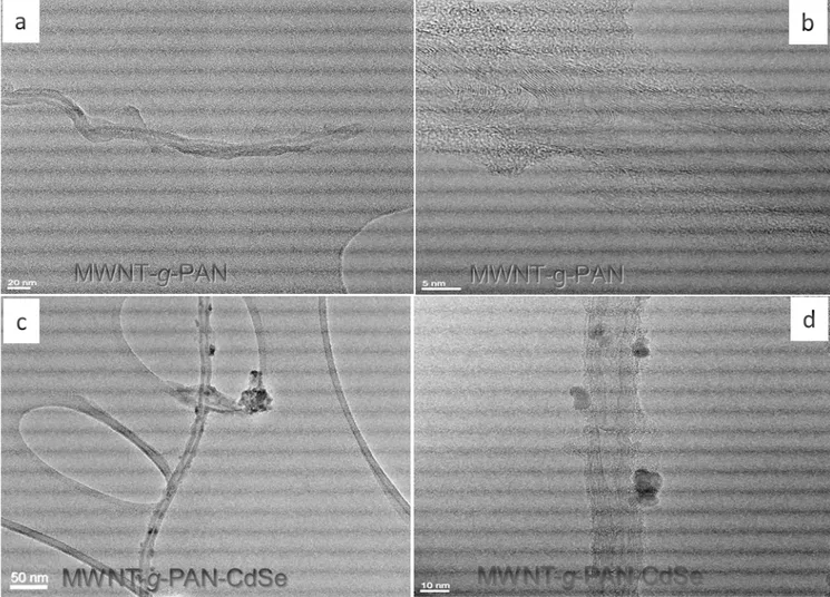
The formation of CdSe nanocrystals on MWNT-g-PAN surface is confirmed by the TEM images in figure 6.4. The samples for TEM were prepared by deposition of one drop of dispersion (∼5mg in 1 mL ethanol) on carbon coated copper grid, followed by solvent evaporation. The dispersion had been previously purified to remove free PAN homopolymer, therefore the feature observed in the micrograph of figure 6.4 should be only due to the MWNTs with covalently attached polymer. The presence of CdSe NPs attached to MWNT-g-PAN is clearly shown in the micrographs of figures 6.4 c and d, in which 5∼10 nm sized CdSe nanocrystals and some larger aggregates are attached on the surface of MWNT-g-PAN. Clearly, the presence of the grafted PAN chains favor the localized growth of CdSe nanoparticles selectively attached to the sidewalls of MWNT-g-PAN, possibly due to both unspecific interaction and of specific coordination of CN groups with the Cd2+ outer ions of the CdSe NP surface. The single CdSe nanocrystals immobilized on MWNT-g-PAN are about 5-6 nm in size, as expected from a synthesis performed starting from 0.01 M Cd and Se precursor at pH=8, and according to the experimental results reported by Kenji et al. and Zhongli Lei et al.30 These authors studied the influence of the reactions conditions on the size of CdSe nanoclusters obtained by using a soluble PAN as the polymeric stabilizer.
119
Figure 6.4 TEM micrographs recorded from the hybrid MWNT-g-PAN (a, b) and the
nanocomposite MWNT-g-PAN/CdSe NPs (c, d).
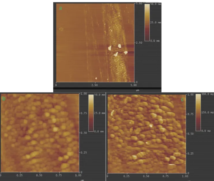
Further investigation on the MWNT-g-PAN/CdSe nanocomposite was performed by Atomic Force Microscopy. A diluted dispersion in DMF was deposited onto untreated glass substrate by dip coating and annealed under vacuum for 5 hr at 80 °C. Tapping mode AFM images of the surface of MWNT-g-PAN/CdSe are shown in figure 6.5. In figure 6.5a, the presence of nanosized spherical objects can be observed on the surface of MWNTs at a low magnification (frame of 5×5 µm2
). The higher magnification micrographs of figure 6.5b and 6.5c correspond to the height and phase images, respectively, at the scale of 1×1 µm, in which the dominant morphological feature is the presence of spheroidal particles with relatively smooth but irregular surface and dimension in the range of 10∼50 nm, probably consisting of CdSe nanoparticles aggregates embedded in the polymer layer grafted on the MWNT surface.
120
Figure 6.5 Tapping mode AFM images of the surface of /MWNT-g-PAN/ CdSe grown on glass
substrate by dip coating and annealed under vacuum at 80 °C (a) 5X5 micron, (b, c) the magnified view (1X1 micron) of height and phase, respectively.
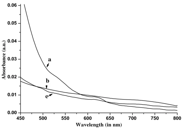
The UV-VIS absorption spectrum of dispersion in DMF (29 mg in 10 mL) of MWNT-g-PAN/CdSe and MWNT-g-PAN/CdSe, the latter obtained by growing CdSe in the presence of free poly(acrylonitrile) using the same method and amount of the precursors as in the synthesis of MWNT-g-PAN/CdSe are shown in figure 6.6. In the presence of CdSe nanocrystals a new weak absorption band can be observed in the UV-VIS spectra of both MWNT-g-PAN and poly(acrylonitrile) with maximum at around 625 nm, whereas pure MWNT-g-PAN shows no specific absorption besides the background one due to scattering from the nanotubes at this wavelength. The size of the CdSe nanocrystals can be determined from equation 6.1,31 in which D (nm) is the size of a given nanocrystal, and
λ
(nm) is the wavelength of the lowest energy exciton absorption peak attributed to the CdSe nanocrystals. According to equation 6.1, the CdSe121
nanocrystals size attached on MWNT-g-PAN/CdSe was calculated to be about 5.9 nm by using the excitonic absorption peak at 625 nm, in good agreement with the TEM results.
ܦܥ݀ܵ݁ = (1.6122 ×10⁻⁹)λ4 − (2.6575 ×10⁻⁶) λ3 + (1.6242 ×10⁻³) λ2− (0.4277) λ + (41.57) (Eq.
6.1) The extinction coefficient can subsequently be calculated as ε=646298.105
Lmol-1 cm-1 from equation 6.2, 32 in which D= 5.9 nm.
ε[CdSe]= = 5857×(D) 2.65 (Eq. 6.2)
Finally, by using the Lambert-Beer's law and assuming therefore a linear relationship of ε vs. concentration, a nominal molar concentration (C) of the CdSe chromophore can be estimated:
C=A/εL = 1.02×10⁻⁴
mol/L (Eq. 6.3) where A is the absorbance of the first exciton absorption peak corrected for the background scattering and L is the pathlength within the sample (1 cm cuvette).
We estimated the concentration of CdSe nanocrystals in the solution of MWNT-g-PAN/CdSe using the experimentally determined extinction coefficients of the QDs (eq. 6.3) and their band-edge absorbance intensities (Figure 6.6a). The MWNT-g-PAN/CdSe mixture used for the UV-VIS analysis was 29 mg dispersed in 10 mL DMF, corresponding to a total 9.6×10⁻⁵
moles (18.3 mg) CdSe as calculated from the precursors fed to the reaction. Based on the result of eq. 6.3 the calculated yield of CdSe nanoparticles was only about 1.06 %. However, it should be mentioned that the nominal extinction coefficient of CdSe NPs is reported to be lowered by the presence of carbon nanotubes due to scattering and/or adsorption,28 therefore the yield might have been underestimated.
122 450 500 550 600 650 700 750 800 0.00 0.01 0.02 0.03 0.04 0.05 0.06
a
b
A b so r b a n c e ( a .u .) Wavelength (in nm)c
Figure 6.6 UV-VIS absorption spectra of; a) PAN-CdSe; b) PAN; c)
123
6.2 Synthesis of CdSe nanoparticles in the presence of poly(thiophene-b-acrylonitrile)
As discussed previously, a good control on the particle size of quantum dots is a pre-requisite for fully exploiting their unique properties A variety of methods to achieve such control have been reported, including lithographic methods,33 size-selective precipitation techniques,34 self-assembly techniques,35 and laser photolysis.36 Furthermore, for many applications the QDs of controlled size must be dispersed in a variety of matrices, where aggregation and agglomeration must be prevented.37 Surface modification of nanoparticles by chemical grafting or adsorption of low molecular weight or polymeric species can be adopted not only to control the particle size during their growth (and thus the optical property of the QDs), but also to promote their dispersibility in polymer nanocomposite by preventing aggregation and improving their compatibility with the polymer matrix.38, 39
In the previous chapters the concepts of hybrid bulk heterojunction and of the importance of having nanosized domains of phase-separated electron donors and acceptors, and thus of the presence of well-dispersed QDs in such systems, has been discussed in relation to the achievable PV efficiencies.40 Purely organic nanophase-separated systems may be attained by using block copolymers consisting of covalently joined donor and acceptor segments.41 In a similar approach, semiconductor nanoparticles may be synthesized or dispersed within a block copolymer acting as a templating matrix, where one block is a conjugated polymer donor and other contains functional groups capable of stabilizing the acceptor nanoparticles.28 For example, inorganic nanoclusters of CdS have been synthesized in situ within a carboxylic acid-functionalized block copolymer in aqueous phase.42 Block copolymer/semiconductor nanocomposites intended for applications involving photonic band gap devices43 synthesized so far include a wide range of copolymers used as matrix, such as PS-b-P2VP (polystyrenes-block-poly(vinylpyridine)s), PS-b-PB (polystyrene-block-polybutadiene), PS-b-PIB (polystyrene-block-polyisobutylene),44 PB-b-PEO (polybutadiene-block-poly(ethylene oxide)s),45 PS-b-PPH (polystyrene-block-poly-m-vinyltriphenylphosphine),46 and PAN-b-PEG-b-PAN (polyacrylonitrile-block-poly(ethylene glycol)-block-polyacrylonitrile).28
The PAN homopolymer is a particularly effective templating matrix for the controlled synthesis of nanoparticles, mainly due to the chelating effect of the CN group.28On the other hand, block copolymers containing a π-conjugated polymer, such as P3HT, may generate unique self-assembled nanostructures with appropriate shape of conjugated polymer domain through which, for example, the photogenerated charges can percolate to the electrodes in a PV device.
A block copolymer of poly(3-hexylthiophene) and poly(acrylonitrile) (P3HT-b-PAN) was therefore selected as a candidate for the controlled growth of CdSe NPs stabilized by the CN groups
124
of the dielectric PAN block, resulting in a nanocomposite material in which an intimate contact between CdSe NPs and semiconducting P3HT domain could be achieved. The synthesis of a P3HT-b-PAN copolymer by “click” reaction of alkynyl-terminated rr-P3HT with azide-terminated PAN has been already described in chapter 4. In the solution containing Cd2+ ion and the block copolymer, in an initial stage the solvated PAN chains are expected to efficiently capture Cd2+ ions from the solution due to the coordinative bonding between the CN groups of the PAN blocks and Cd2+; the resulting high local Cd2+ concentration is likely to evolve into the nucleation of CdSe NPs wrapped by the block copolymer. The same PAN blocks of the wrapping copolymer may also play a role in the subsequent stabilization of the nucleated CdSe nanoparticles.
Once the P3HT-b-PAN/CdSe hybrid is generated, the P3HT block is expected to favor solubility of the block copolymer/ nanoparticle assembly in a range of organic solvents, to contribute to its stabilization by steric effect, and to allow blending of this hybrid material with pure P3HT, thus making possible the preparation of thin hybrid films with variable concentrations of CdSe NPs by spin coating or casting. Furthermore, the presence of end chain functionalities in each block of P3HT-b-PAN (the alkyl bromide in PAN and allyl/vinyl in P3HT, deriving from the synthetic procedure adopted for the synthesis of the individual blocks) will also allow further modification of the block copolymer/CdSe system by promoting specific interaction or chemical banding with other compounds such as, for example carbon nanotubes.47
6.2.1 Synthetic procedures
For the synthesis of CdSe nanoparticles in the presence of a P3HT-b-PAN block copolymer as a polymeric stabilizer the two precursor solutions of Na2SeSO3 and CdSO4 (both 0.1 M) were
prepared as described in section 6.1.1. P3HT-b-PAN (140 mg) was dissolved in a mixture of dry THF (15 mL) and DMF (5 mL) in a three-necked round bottom flask with magnetic stirrer and deoxygenated and the flask was placed on oil bath at 50 °C. After solubilization of the copolymer, the freshly prepared solution of CdSO4 (3 mL, 0.1 M) was transferred into the mixture after raising
the pH to 8 by dropwise addition of a diluted NaOH solution. Then a 1:1 stoichiometric ratio of Na2SeSO3 (3 mL, 0.1 M) was injected into the reaction solution kept under vigorous stirring. After
stirring at 75 °C for 5 hr under nitrogen atmosphere in dark, the light-red colored resultant mixture was allowed to cool down to room temperature, and then it was precipitated in MeOH, filtered, and redissolved in a THF/DMF (3:1) mixture. The resultant P3HT-b-PAN/CdSe mixture consisting of a theoretical (that is, calculated by assuming quantitative conversion of the CdSe precursors) ∼57 mg of CdSe in 140 mg of copolymer was stored in the dark at room temperature (Scheme 6.2).
125
6.2.1 Results and discussion
The block copolymer used for the in-situ template synthesis of CdSe NPs was obtained by the copper-catalyzed highly efficient Huisgen’s “Click” reaction of alkynyl terminated rr-P3HT with azide terminated PAN, as described in chapter 4. As the two end-functional homopolymeric block precursors have no common solvent, the coupling reaction had been performed in a 3:1 THF:DMF mixed solvent. Purification of the resulting block copolymer from any unreacted precursor was performed by successive redisperstion and filtration with pure THF and DMF. The azide-terminated PAN homopolymer was synthesized by atom transfer radical polymerization (ATRP) from an initiator bearing the azide function, whereas the alkynyl-terminated P3HTs was prepared by subsequent Grignard metathesis polymerization of a dibromo thiophene derivative followed by Sonogoshira coupling reactions. The PAN block was selected as it is expected to interact specifically with the growing CdSe crystals by coordinative and/or dipolar interaction of the –CN groups with the Cd2+ cation on the nano-crystal edge, thus promoting localized nucleation and controlled growth. The resulting P3HT-b-PAN/CdSe nanocomposite was expected to be suitable as active layers in solid state PV devices as it should be characterized by a well-defined interface in which, due to the minimum distance of acceptor phase (CdSe nanocrystals stabilized by the PAN block) from an excitation point of the donor phase (P3HT), charge transfer would be likely to occur before exciton relaxation to the ground state. If a monophase-seprated morphology arises from the self-assembly of the two immiscible polymer blocks, the PAN/CdSe domains could promote the formation of a percolating semiconducting CdSe NPs (acceptor) while promoting intimate contact with the covalently bound conjugated P3HT domains forming a percolating semiconducting donor nanophase (hole-transporting).
126
Scheme 6.2 Controlled growth of CdSe NPs on P3HT-b-PAN
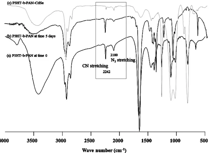
The formation of CdSe NPs in the presence of a poly(3-hexylthiophene)-b-poly(acrylonitrile) (P3HT-b-PAN) copolymer is shown in scheme 6.2.The FTIR spectra of the block copolymer as well as that of its end-functional polymeric precursors and of the hybrid obtained after the controlled growth of CdSe nanocrystals in the presence of the templating P3HT-b-PAN are shown in figure 6.7. The FTIR spectrum of the purified block copolymer still shows a small azide peak at 2100 cm-1, due to residual azide-terminated unreacted PAN not completely removed from the block copolymer., The decreased intensity of the CN stretching absorption band at 2242 cm-1 in the hybridized materials as shown in figure 6.7c, can be ascribed to the coordination of Cd2+ with CN groups in P3HT-b-PAN/CdSe, already reported by Z. Lei et al. for a PAN/CdSe hybrid.28
127
Figure 6.7 FTIR spectra of the P3HT-b-PAN copolymer prepared by “Click reaction from the
respective end-functional alkynyl-P3HT and azide-PAN; a) reagents at time 0; b) block copolymer after 5 days reaction; c) hybrid obtained by growth of CdSe NPs in the presence of templating P3HT-b-PAN.
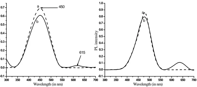
The optical properties of P3HT-b-PAN were studied by UV–VIS and fluorescence (or photoluminescence, PL) spectroscopy in solution (15 mg in 10 mL DMF/THF 1/3). The UV–VIS spectra of the P3HT homo polymer and of P3HT-b-PAN show very similar absorption maxima at λ=450 nm, attributed to the excitation of electrons in the π-conjugated system of the P3HT block (Figure 6.8a, left). The maximum of the absorption depends on the conjugation length of the polymer, 48 that is, on the fraction of structural defects and thus on the average length of the regioregular segments, being shifted batochromically with increasing conjugation length (related to regioregularity and molecular weight) up to a threshold value of about 20 repeat units. The molecular weight of alkynyl-terminated P3HT homopolymer precursor was determined as Mn= 10300 mol.L-1 by SEC analysis, whereas 1H NMR indicates an average of about 60 repeating units (corresponding to a Mn≈ 10138) by integration the resonances of protons on the alkynyl chain end
128
versus the hexyl side chain protons for a polymer that had been characterized as containing HT coupling of over 98%, (see chapter 3). The block copolymer/CdSe hybrid shows an additional absorption maximum at 615 nm, corresponding to the exciton absorption of semiconducting CdSe particles with a band gap of 2.76 eV and an enhanced intensity of the P3HT absorption indicating some interaction with the π–π* system of the conjugated polymer. The absorbance values were used to calculate the nanocrystal diameter according to eq. 6.1, while the CdSe nanocrystal concentration was calculated based on the previously calculated molar extinction coefficients for the CdSe QDs. The particle size of the CdSe nanocrystals was thus determined as d=5.3 nm by using the exciton absorption at λ= 615 nm, while the concentration was 3.6×10⁻³
mol/L of CdSe.
Figure 6.8 UV-VIS (left) and photoluminescence (right, excitation wavelength 390 nm) spectra of:
a) P3HT-b-PAN; b) P3HT-b-PAN/CdSe hybrid in 1/3 DMF/THF mixed solvent. Spectra are corrected for the background scattering absorption.
The presence of CdSe nanoparticles in the hybridized block copolymer is confirmed by a comparison of the photoluminescence spectra shown in figure 6.8. The PL spectrum of pure P3HT-b-PAN shows a single emission band with maximum at λ=480 nm, red shifted by 30 nm with respect to the corresponded absorption maximum of P3HT.
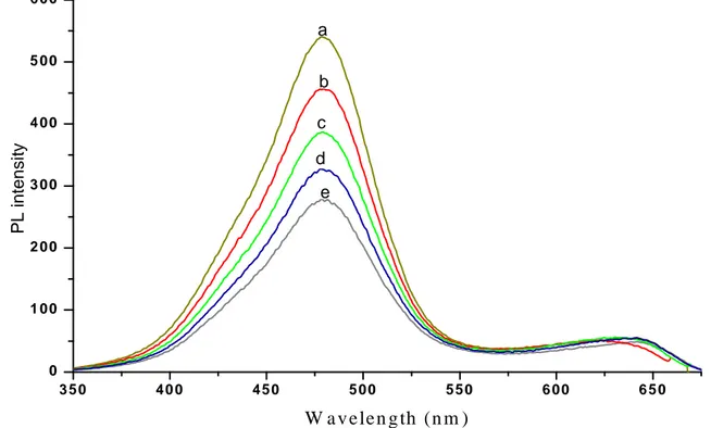
The PL spectrum recorded from the P3HT-b-PAN/CdSe hybrid presents an emission peaking at 630 nm from the CdSe QDs (Figure 6.8b, left) in addition to the P3HT emission at 480 nm that appears to be of slightly lower intensity with respect to that of the pure copolymer. Figure 6.9 shows the room temperature fluorescence spectra of the P3HT-b-PAN/CdSe hybrid recorded at excitation
300 350 400 450 500 550 600 650 700 -0.1 0.0 0.1 0.2 0.3 0.4 0.5 0.6 0.7 A b so rp ti o n Wavelength (in nm) 615 450 a b 300 350 400 450 500 550 600 650 700 -0.1 0.0 0.1 0.2 0.3 0.4 0.5 0.6 0.7 0.8 0.9 1.0 P L i n te n si ty Wavelength (in nm) a b
129
wavelengths from 300 to 390 nm. A significant decrease in the intensity of the fluorescent emission of P3HT at 480 nm can be observed as the result of comparatively small decreases of the excitation wavelength. The intensity of the P3HT absorption at 480 nm decreases in intensity by 45 %, without significant changes in the absorption maxima. This is the result of decreasing absorption of the incident photons by the active π-π* transition as the excitation is lowered towards wavelengths corresponding to an absorption minimum (and then to a different absorption band that is not fluorescent active) in the UV-VIS spectrum. On the other hand, the intensity of the emission at 650 nm attributed to the CdSe nanoparticles fluorescence, undergoes a small fluctuation in intensity (in a 14% range) and possibly a batochromic shift on increasing the excitation wavelength.
3 5 0 4 0 0 4 5 0 5 0 0 5 5 0 6 0 0 6 5 0 0 1 0 0 2 0 0 3 0 0 4 0 0 5 0 0 6 0 0 PL i n te n s it y W a v e le n g th (n m ) a b c d e
Figure 6.9 Fluorescence spectra of P3HT-b-PAN/CdSe nanocomposite under increasingly high
excitation wavelength (a−e) 390, 380, 370, 360, 300 nm.
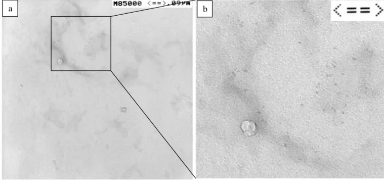
The P3HT-b-PAN/CdSe hybrids morphology was investigated by Transmission Electron Microscopy (TEM) and scanning probe microscopy techniques (AFM). In the TEM micrograph of figure 6.10a, the CdSe nanocrystals embedded in the block copolymer can be clearly distinguished at higher magnification by digital zooming of the same image (Figure 6.10b), isolated particles can be identified, their size being determined as d= 4∼5 nm with an apparently nearly mono-dispersed size distribution. This is in a good agreement with the average size of 5.3 nm calculated from the spectroscopic data.
130
Figure 6.10 TEM images of a) P3HT-b-PAN/CdSe hybrid; b) enlarged view of the surface within
the squared box.
Further insights in the surface morphology of P3HT-b-PAN/CdSe were obtained by AFM analysis of a thin film prepared by casting one drop of highly diluted dispersion of the hybrid material (∼1 mg in 5 mL of mixed DMF/THF 1/3 solvents) onto a glass slide at room temperature, followed by solvent evaporation and annealing at 120 °C for 2 hr under reduced pressure. AFM analysis was performed in tapping mode. In figure 6.11a isolated CdSe quantum dots appear as brighter spots within a darker polymer matrix background in the height image (left) (here the brighter shade indicates a bulge or protuberance) as clearly shown by the profile on the right image. On the contrary, in the phase image of figure 6.11b (center) image the darker spots correspond to the CdSe QDs because the darker shade indicates a higher modulus, as expected for the hard inorganic nanoparticles with respect to the comparatively softer polymer matrix. In figure 6.11a the observed aggregates with size in the 50∼100 range may be due to polymer-coated unstabilized CdSe nanoclusters. The size of nanocrystals was determined as about 5−7 nm from the vertical displacement of the AFM tip (the lateral displacement is related to the much larger lateral size of the AFM tip), in good agreement with the results of UV-VIS and TEM analyses.
131
Figure 6.11 AFM images of P3HT-b-PAN/ CdSe hybrid recorded as height (left), phase (middle)
and height profile (in nm scale, right). The different magnifications correspond to a scanned surface of 3×3 µm (a) and 1×1 µm (b). (Film obtained by casting and evaporating one drop of dispersion of the hybrid containing a 1.2×10⁻³
mol·L-1 concentration of CdSe as calculated by UV-Vis absorption). The height profile to the right was recorded along the highlighted scanning line drawn on the height image (left).
a
b
100 80 60 40 20 0 4 3 2 1 0 -1 -2 -3 -4 X[nm] 3 2.5 2 1.5 1 0.5 0 4 3.5 3 2.5 2 1.5 1 0.5 0 X[µm]132
6.3 Preparation of polymer-covered CdSe nanoparticles stabilized by rr-P3HT-monophosphonic acid
Composites of inorganic semiconductor nanoparticles (quantum dot) with conjugated or stimuli-responsive polymers are of potential use as active layers in devices such as organic photovoltaic cells (OPV),49 light emitting diodes,50 field-effect transistor51 and actuators.52 Among conjugated polymers, alkylthiophene) and in particular regioregular (head-to-tail) poly(3-hexylthiophene) (rr-P3HT) has been especially investigated because of its good solubility in the most common organic solvents and easy processibility. Photoactive layers, assembled as an interpenetrating network of electron donating conjugated polymer as the donor and QDs as the acceptor is an example of hybrid active layer for a photovoltaic cell. 53 Such hybrid materials combine the advantages of high electron mobility and chemical stability typical of inorganic materials, with the superior processing and mechanical properties of polymers. In addition, the combination of light harvesting capability of nanocrystals and conjugated polymers enlarges the absorption range, leading to higher maximum theoretical conversion of sunlight.54 Example of inorganic particles used in such systems include CdSe,55, 40 TiO2, 56 and ZnO 57 in different
morphologies such as nanospheres, nanorods or tetrapods. Whatever processing procedure has been employed, controlling the final morphology and dispersion of nanocrystals within the polymer has been difficult because of the incompatibility of organic polymer and inorganic semiconductor. Hence, a surfactant is generally required to promote the dispersion of inorganic nanocrystals in solvents and polymers. In earlier studies58 on hybrid solar cells, conjugated polymer-inorganic nanoparticles composites were prepared by mixing in organic solvent the polymer with the inorganic nanoparticles colloidally stabilized by e.g. trioctylphosphine oxide (TOPO). However, in most cases nanoparticle aggregation could not be avoided in the resulting blend. Furthermore, the presences of TOPO contaminant at the interface would be detrimental to the PV layer efficiency, causing poor charge transfer between conjugated polymers and nanoparticles.59
To date, only a few elegant studies have investigated the possibility of replacing such insulating layer by direct integration of QDs into functionally modified conjugated polymers matrices via ligand exchange to replace the original insulating surfactants,60 or by electrostatic interaction, or polymer growth from the QDs’ surface61 to achieve a more controlled interface composition and morphology.
133
In the following, allyl/phosphonic acid-terminated regioregular poly(3-hexylthiophene) (P3HT-PA) was used as the polymer ligand CdSe QDs to replacing the original TOPO stabilizer The synthesis of P3HT-PA is described in chapter 3. TOPO-capped CdSe QDs were synthesized using a reported procedure,62 then treated with pyridine to partially replace the TOPO ligand employed for controlling the QD growth, and subsequently processed to ligand exchange the mixed pyridine/TOPO stabilizer with P3HT-PA.
6.3.1 Synthesis of TOPO-capped CdSe Nanoparticles
In a typical reaction, according to the method reported by Peng et al.62 CdO (0.0514 g), tetradecylphosphonic acid (TDPA, 0.2232 g), and trioctylphosphine oxide (TOPO, 3.7768 g) were loaded into a 250 mL flask. This was placed on oil bath at 320 °C under Argon with vigorous stirring. After complete dissolution of CdO in the TDPA/TOPO mixture, the temperature was decreased to 270 °C. A solution of Se powder (0.0411 g) was dissolved in 2.4 mL of trioctylphosphine (TOP) and stirred continuously to form a TOPO-CdSe dispersion, which was then injected into the hot CdO/TDPA/TOPO mixture. A sudden decrease in temperature was observed. The temperature was then gradually raised to 250 °C and the reaction was allowed to age for 5 minutes. The reddish solution obtained was cooled to room temperature under argon atmosphere. Addition of excess anhydrous methanol to the solution resulted in the reversible flocculation of the nanoparticles. The flocculate was separated from the supernatant by centrifugation. During this purification TDPA was completely removed from the on the CdSe NPs surface, as shown by FTIR and 1H NMR analysis. Excess methanol was removed under vacuum to give TOPO-capped CdSe nanoparticles. The resultant particles were redispersed in toluene to give an optically transparent reddish brown dispersion that was characterized by UV-Vis spectroscopy, Dynamic Light Scattering (DLS), TEM and AFM. The TOPO capped CdSe NPs were stored in dry hexane (50 mL) in cool place.
6.3.2 Ligand exchange with pyridine
From the mixture of CdSe/TOP/TOPO in hexane, 10 mL was taken in a 50 mL round-bottom flask, and then the solvent was removed by rotary evaporation. The resultant CdSe/TOP/TOPO solid (109 mg) was dissolved in 5 mL of pyridine and allowed to stir at 65 °C for 1 hr. After surface ligand exchange with pyridine, the hexane (30 mL) was added to precipitate CdSe, as the pyridine stabilized particles are no longer dispersible in hexane. The orange/red suspension was centrifuged to collect the solid, which was again redissolved in ~ 5 mL of pyridine.
134
This cycle was repeated seven times, while being monitored by both 1H and 31P NMR to check the progressive replacement of TOPO by pyridine as the adsorbed species on the CdSe nanoparticles surface. The final CdSe/pyridine solid was redissolved in 10 mL of pyridine to make the CdSe/ pyridine stock solution. Of this solution, 5 mL was dried (first in dry N2 stream followed by vacuum
at room temperature until constant weight) to give 40 mg of solid which was subjected to NMR analyses. The 1H NMR spectrum recorded from a tube filled with 15 mg of TOPO/pyridine/CdSe and 1 mL CDCl3 shows resonances between 1.0 and 1.8 ppm (broad, aliphatic protons from residual
phosphorus compounds) in addition to the pyridine resonance at 8.73 (dd, 2H, H ortho to N in pyridine), 7.58 (t, 1H, para) and 7.27 (dd, 2H, meta) ppm. This is in agreement with literature data,38 suggesting that 10-15% TOPO remains on the surface. Using a weighed amount of acetone (2µL in 1 mL CDCl3) as an internal standard and based on 1H NMR integration, the amounts of
phosphorus compound (expressed as TOPO) and pyridine in the NMR tube (1 mL solution) were calculated to be 1.9 and 2.4 mg, respectively. Since the amount of TOPO/pyridine/CdSe mixture was 15 mg. The weight ratio of CdSe : TOPO : pyridine, 10.7 : 1.9 : 2.4 mg.
6.3.3 CdSe NPs stabilization with phosphonic acid-terminated rr-P3HT (P3HT-PA)
For polymer ligand exchange, the pyridine coated nanoparticles (20 mg) were dissolved in 5 mL pyridine and stirred at 50 °C under argon flow until the nanoparticles were totally dispersed in pyridine to get a clear solution. The nanoparticles were precipitated in excess amount of hexane, and precipitate was separated by centrifugation. The supernatant was discarded, and three time precipitate was redissolved/precipitate with pyridine/hexane. Finally pyridine capped-CdSe nanoparticles were stirred as a suspension in 1.5 mL freshly distilled dry THF. At this stage, allyl/phosphonic asymmetric end capped regioregular poly(3-hexylthiophene) (50 mg) was added, and the suspension was stirred for 48 hr at 50 °C. After became a homogenous mixture, excess of THF was removed by distillation, and remaining solution was twice precipitated in methanol and centrifuged. The supernatant was again discarded and P3HT-PA polymer ligand capped CdSe nanoparticles were dissolved in dry chloroform for further characterization, scheme 6.3.
135 N N N Pyridine S C C P OH O OH n C6H13 Ligand exchange P3HT Ligand exchange P O
Scheme 6.3 Ligand exchange multistep procedure to prepare CdSe NPs stabilized with
end-functional P3HT-PA
6.3.4 Results and discussion
The TOPO ligand is commonly used to cap and passivate the surface of CdSe quantum dots for a variety of reasons: it coordinates the surface cadmium atoms, it forms a protective layer against sintering, provides solubility, and maintains good optical properties. By refluxing the TOPO-capped CdSe QDs in a pyridine solvent, it is reported that one can replace more than 90% of the adsorbed TOPO with pyridine.63 This exchange of ligands modifies the surface of the quantum dots and increases their conductivity in the solid state. The replacement of TOPO with pyridine make it easier to carry on a further ligand exchange with the phosphonic acid terminated P3HT ligand, as pyridine is a weak-binding ligand.
Here, for the preparation of CdSe nanoparticles stabilized by the macromolecular ligand consisting of a P3HT chain terminated with a phosphonic acid group, a convergent approach was followed. Firstly, TOPO capped CdSe nanoparticles were prepared, as the precursors for polymer capped CdSe nanoparticles. In a second stage the polymer-stabilized CdSe nanoparticles would be obtained by ligand replacement. The TOPO-capped CdSe particles were synthesized as reported in the literature to obtain nanocrystals with controlled size.23 Average diameter and size uniformity of the TOPO-capped CdSe NPs were determined by DLS (d = 2.5 ± 0.25 nm) (Figure 6.12), in good agreement with the average size of 2.3 nm reported in the literature.24 The results of UV-VIS spectroscopy and of TEM, AFM and microscopic examination are presented and discussed below in
136
this section. The colloidal stability of the TOPO-capped particles is due to the high affinity of TOPO for Cd2+ and to its bulky nature that also provides steric hindrance. The resultant increased surface passivation is reported to lead to higher photoluminescence efficiency of the nanoparticles.64,65,66
Figure 6.12 TOPO capped CdSe NPs size determination by DLS
The surface morphology of the CdSe NPs was investigated by FTIR spectroscopy to confirm the capping of the particles by the passivating agent. TOPO absorbs strongly at 2957, 1466 and 1154 cm-1 corresponding to the methylene C−H, P=O asymmetric (νasym) and symmetric (νsym)
stretching absorption, respectively, the position of which depends on the type of attached group. In figure 6.13, as CdSe nanoparticles coordinate with TOPO, the intensity of the CH2 stretching
absorption at 2948 cm-1 decreased, as evidenced by the decomposition of the C−H stretching absorption envelope in the 3000−2800 cm-1
range shown reported in the inset of figure 6.13. Moreover, a shift of 10 cm-1 (ν = 1456 cm-1) to lower wavenumbers from the characteristic stretching in absorption of TOPO (νsym P=O = 1466 cm-1) was observed. This shift has been
reported previously for TOPO-capped CdSe nanoparticles and attributed to the binding of TOPO to Cd2+ sites on the CdSe nanoparticles surface.37
137
a
c
d
b
3000 2500 2000 1500 1000Wavenumber (cm
-1)
a
c
d
b
3000 2500 2000 1500 1000Wavenumber (cm
-1)
2800 2850 2900 2950 3000@${[0|4|TREE|148|248159614]}<OriginStorage><ColumnInfo Enable="2" Branch="1"><ImportFile>C:\Users\utente\Desktop\TOPO-TDPA 1.asc</ImportFile></ColumnInfo></OriginStorage>
2800 2850 2900 2950 3000
2800 2850 2900 2950 3000
@${[0|4|TREE|148|248159614]}<OriginStorage><ColumnInfo Enable="2" Branch="1"><ImportFile>C:\Users\utente\Desktop\TOPO-TDPA 1.asc</ImportFile></ColumnInfo></OriginStorage>
TOPO TOPO-CdSe
a
c
d
b
3000 2500 2000 1500 1000Wavenumber (cm
-1)
a
c
d
b
3000 2500 2000 1500 1000Wavenumber (cm
-1)
a
c
d
b
3000 2500 2000 1500 1000Wavenumber (cm
-1)
2800 2850 2900 2950 3000@${[0|4|TREE|148|248159614]}<OriginStorage><ColumnInfo Enable="2" Branch="1"><ImportFile>C:\Users\utente\Desktop\TOPO-TDPA 1.asc</ImportFile></ColumnInfo></OriginStorage>
2800 2850 2900 2950 3000
2800 2850 2900 2950 3000
@${[0|4|TREE|148|248159614]}<OriginStorage><ColumnInfo Enable="2" Branch="1"><ImportFile>C:\Users\utente\Desktop\TOPO-TDPA 1.asc</ImportFile></ColumnInfo></OriginStorage>
TOPO TOPO-CdSe
2800 2850 2900 2950 3000
@${[0|4|TREE|148|248159614]}<OriginStorage><ColumnInfo Enable="2" Branch="1"><ImportFile>C:\Users\utente\Desktop\TOPO-TDPA 1.asc</ImportFile></ColumnInfo></OriginStorage>
2800 2850 2900 2950 3000
2800 2850 2900 2950 3000
@${[0|4|TREE|148|248159614]}<OriginStorage><ColumnInfo Enable="2" Branch="1"><ImportFile>C:\Users\utente\Desktop\TOPO-TDPA 1.asc</ImportFile></ColumnInfo></OriginStorage>
TOPO TOPO-CdSe
Figure 6.13 FTIR of a) TOPO; b) TOPO capped CdSe NPs; c) P3HT-PA ligand; d), P3HT-PA
capped CdSe NPs
The ligand exchange of TOPO/pyridine stabilized CdSe NPs and with P3HT-PA was monitored by FTIR, 1H and 31P NMR spectroscopy. The results confirmed that the adopted two-step ligand exchange procedure allowed to successfully preparation of P3HT-PA stabilized CdSe NPs with starting from TOPO capped CdSe NPs. From the FTIR spectrum, the usual shift to lower wavenumbers of the P=O stretching absorption from 1460 cm-1
for the free α-ally/ω-phosphonic acid-terminated rr-P3HT to 1448 cm-1 was observed upon attachment onto the surface of CdSe nanoparticles (Figures 6.13c and d). In figure 6.14, are reported the 1H NMR spectra recorded upon partial exchange of the original TOPO ligand with pyridine, and subsequently with the final asymmetrically ally/phosphonic acid terminated rr-P3HT ligand. We begin by presenting in figure 6.14 the 1H NMR spectrum of TOPO/TDPA, CdSe/TOPO, the polymer rr-P3HT-PA, and a CdSe/TOPO/P3HT-PA mixture in chloroform-d solution. For TOPO itself, distinct resonances a, b, and d are observed at 1.56, 1.65, and 1.38 ppm, respectively, for CH2 protons and resonance e at
0.88 ppm for the terminal CH3 group. The remaining CH2 groups (c) yield a set of superimposed
resonances at around 1.28 ppm. When bound to CdSe/TOPO QDs, these proton resonances are not
2957 2916
2851
138
significantly shifted relative to TOPO free in solution but instead are all broadened as shown in figure 6.14b, an effect attributed to the close-packing TOPO ligands on the surface of nanoparticles. In figure 6.14c, the efficiencies of the pyridine exchange on the CdSe NPs surface is confirmed by the presence of the pyridine resonances at 8.62, 7.68 and 7.30 ppm. The adsorbed species on CdSe NPs after the pyridine treatment are in the molar ratio pyridine : TOPO= 2.4 : 1.9 according to the integrals of the respective proton resonances in spectrum 6.14c. In figure 6.14d, the polymer attachment onto the CdSe NPs surface can be recognized by the absence of resonance of pyridine, replaced by P3HT-PA. Direct evaluation of the adsorbed TOPO/P3HT-PA ratio was not possible from spectrum 6.14d due to the overlapping and broad proton resonances, but considering the proton resonance of CH3 in hexyl chain, the TOPO CH3 proton was determined, in the molar ratio
1.16×10⁻⁶ : 2.07×10⁻⁶
of P3HT-PA and TOPO, respectively. As the NMR tube contained 15 mg of TOPO/P3HT-PA/CdSe hybrid and acetone (2 µL In 1 mL CDCl3) as an internal standard, the
amount of P3HT-PA was estimated as 1.16×10⁻⁶
moles, thus the weight of P3HT-PA (Mw=4556, by 1H NMR, given in chapter 3) in 15 mg of the hybrid was calculated as 5.3 mg, i.e., 35.4 wt % and TOPO was 0.8 mg, i.e. 5.3 wt% of the hybrid material.
Figure 6.14 1H NMR spectra of; a) TOPO; b) TOPO capped CdSe NPs; c) Pyridine capped CdSe
NPs; d) P3HT-PA capped CdSe NPs (* assigned to the TOPO CH3 proton).
chloroform
139
The phosphorus atom present in the modified CdSe NPs can be a suitable label for studying the ligand adsorption and replacement by means of the 31P NMR spectroscopy. As reported in the literature,67 the 31P NMR spectra of CdSe NPs stabilized with a phosphor-containing ligand are characterized by broad resonances as opposed to those of the free ligands, due to anchoring P=O:Se moieties on the surface. The 31P NMR resonance from TOPO adsorbed on the CdSe surface is centered at ~35 ppm, whereas that of free TOPO occurs at ~49 ppm (Figures 6.15d and c). The TDPA resonance at 33 ppm can no longer be detected in the 31P NMR spectrum of CdSe-TOPO of figure 6.15c, indicating that the repeated cycles of purification were effective in removing all TDPA from CdSe NPs surface. The large downfield shift with respect to “free” TOPO suggests that phosphine oxide is tightly bound to the surface of the NPs, possibly as the results of the occurrence of a chemical reaction on the nanoparticle surface. The breadth of the peak is attributed to the inhomogeneous distribution of the magnetic environments on the NPs surface.67 A similarly large downfield shift of the 31P resonance in the spectrum of the P3HT-PA anchored onto CdSe with respect to the “free” P3HT-PA from ~55 ppm to ~32 ppm, is shown in figure 6.15b and a. In figure 6.15a, a broad resonance at 32 ppm is due to the phosphonic acid group of P3HT-PA, whereas the resonance at 37 ppm could belong to the phosphine oxide group of TOPO although such narrower than in 6.15c, and at 39 ppm the resonance from the internal reference P(O)Me3 can be observed.
After the ligand exchange procedure the, CdSe NPs surface is still covered by both TOPO and P3HT-PA ligands. Using P(O)Me3 as an internal standard (2 µL in 1 mL CDCl3) in the NMR tube
containing 15 mg P3HT-PA/TOPO/CdSe hybrid (in 1 mL CDCl3) the total amount of TOPO and
P3HT-PA within the 1 mL deuterated solvent was calculated as 5.64×10⁻⁷ mol and 3.95×10⁻⁶ mol, respectively, corresponding to a 0.22 : 18 mg weight ratio. The weight ratio of TOPO and P3HT-PA determined by 1H NMR (0.8 : 5.3 mg) does not match with the same ratio calculated from the
31
P NMR spectral data, possibly because in the 31P NMR spectrum the simple integration of phosphorus resonance of TOPO and P3HT-PA cannot give the quantitative amount in the presence of CdSe NPs. The influence of phosphorus in 31P NMR in quantitative estimation has been discussed already by A. Hassinenet al.68
140 S C C P OH O OH n C6H13 P O S C C P OH O OH n C6H13 P O d a c b S C C P OH O OH n C6H13 P O S C C P OH O OH n C6H13 P O d a c b
Figure 6.15 31P NMR spectra of; a) P3HT-PA capped CdSe NPs; b) P3HT-PA; c) TOPO capped CdSe NPs; d) TOPO and TDPA solution mixture in CDCl3.(Chemical shift referred to
trimethyl phosphine oxide as an internal reference with chemical shift at δ=39 ppm.
The optical properties were evaluated by UV-VIS and fluorescence spectroscopic measurements. In Figure 6.16a (left), the UV-VIS absorption peaking at 545 nm recorded from the chloroform solution of TOPO-capped CdSe NPs corresponds to a calculated particle size of 2.8 nm.31 After CdSe NPs ligand exchange with P3HT-PA the main P3HT-PA absorption at 445 nm presents a shoulder due to the presence of the CdSe NPs, both absorptions being slightly shifted bathochromically with respect to the corresponding ones of the parent compounds. The red shift may be due to the loss of control over the particle size during ligand exchange process.
The photoluminescence spectra of the TOPO-capped CdSe NPs, P3HT-PA and P3HT-PA capped CdSe NPs are compared in figure 6.16 (right). For TOPO-capped CdSe NPs, the PL spectrum shows an emission band with maximum at 560 nm (excitation wavelength 415 nm, Figure 6.16a, right). After ligand exchange from TOPO to P3HT-PA, the PL spectrum presents a maximum emission at 580 nm (excitation wavelength of 380 nm) with a small shoulder at 520 nm. The same emission at 580 nm (excitation wavelength 350 nm) is present the PL spectrum of P3HT-PA. 37 32 Internal reference 39
141
Figure 6.16 UV-VIS (left) and photoluminescence (right) spectra of; a) TOPO capped CdSe NPs;
b) P3HT-PA; c) P3HT-PA/ CdSe hybrids with concentration as 10-6 M and in inset the fluorescent image of d) P3HT-PA/CdSe; e) TOPO/CdSe.
In figure 6.17(a–d) are shown the TEM micrographs of CdSe NPs stabilized with different ligands (TOPO, pyridine and P3HT-PA) and dispersed in toluene, hexane and chloroform, respectively. The TOPO-capped CdSe NPs of figure 6.17 a show distinctly the presence of nearly monodispersed spheroidal shaped particles with d=2.5 ± 0.4 nm as well as larger particle aggregates. After treatment with pyridine and precipitation from hexane no significant change in particle size was observed. The micrograph from P3HT-PA capped CdSe NPs reveals excellent particle dispersion in the polymer matrix, as one would expect in case of effective surface coverage by the polymer anchored through its phosphonic acid termination onto the CdSe particles. The average interparticle separation in the composite thin film (seemingly a monolayer) appears to be significantly greater than that observed in the starting TOPO-capped CdSe NPs and no aggregation of CdSe NPs could be detected.
142
Figure 6.17 TEM images of; a) TOPO capped CdSe NPs; b) Pyridine−capped CdSe NPs; c)
P3HT-PA-capped CdSe NPs; d) enlarged selected area from (c) (∼5 ×10⁻³
M CdSe concentration by UV-VIS).
Atomic Force Microscopy investigations were performed with the AFM instrument operated in tapping mode at a scan rate of 0.10 Hz using silicon tips. Images were taken using a Veeco Multimode Nanoscope IIIa and data was manipulated using WSxM 4.0 SPMAGE07 software. In figure 6.18 (a, left) the TOPO−capped CdSe NPs deposited by casting from a ∼100 mg/L solution in toluene appear a scattered particles on the glass substrate. The line scan in height cross section profile in figure 6.18 (a, right) indicates that the surface is very smooth, the nanoparticles size being measured as 2.6 ± 0.5 nm from their height profile, only slightly larger than the value determined by TEM. This difference is expected, however, as in AFM images a systematic error is introduced
143
when measuring such small particles due to the curvature of the AFM tip. Again, the phase image of the sample in figure 6.18 (a, middle) allows to clearly distinguish between the soft polymer matrix and the hard TOPO-capped CdSe NPs monolayer. The AFM images of the pyridine−capped CdSe NPs are also obtained from a thin monolayer prepared by casting a diluted (∼100mg/L) dispersion in hexane onto a glass substrate. The cross-section profile shows that some aggregation occurred during the ligand exchange process from TOPO to pyridine, but the prevailing particle size was still in the range of 2.5 ± 0.5 nm.
Figure 6.18 Tapping mode AFM images of ; a) the TOPO-CdSe NPs; b) Pyridine-CdSe NPs; (Left)
height image, (Middle) Phase image, (Right) Cross-section profile.(5.2×10⁻³
M concentration of CdSe calculated by UV-VIS spectroscopy)
P3HT-PA/CdSe AFM image of figure 6.19 shows the particle size in the range of 3−3.5 nm. This result is in a good agreement with UV-VIS results, which shows the red shift for CdSe NPs. There may be two possibilities for this increment in the size of polymer stabilized CdSe NPs. The first is the loss of control over the particle size during the ligand exchange and another is that polymer footprint area is larger than the TOPO, which shows a bigger diameter than the TOPO-capped CdSe NPs. a b 120 100 80 60 40 20 0 4.5 4 3.5 3 2.5 2 1.5 1 0.5 0 X[nm] Z [n m ] 150 100 50 0 2 1.5 1 0.5 0 X[nm] Z [n m ]
144
Figure 6.19 Tapping mode AFM images of P3HT-PA/CdSe NPs; (Left) height image, (Right)
Cross-section profile.
The P3HT-PA/CdSe hybrid was also characterized by Kelvin probe force microscopy (KFM), particularly suitable for analyzing a material with well-defined electric surface potential distribution and capable of providing images at high spatial resolution ~100 nm with high potential sensitivity ~1 mV. The KFM has been used to map the structural and electric properties of film surface of organic photovoltaic materials; in particular, it can provide information on the charge carrier generation and electron blocking at interface in PV active layers. The KFM probe consists of a non-contact atomic force microscopy tip with a conductive coating to measure the difference between the tip potential and the local surface potential with a lateral and potential distribution below 30 nm and 70 mV, respectively. The instrumental setup adopted for the measurements performed in this work involved a with a constant applied 70 mV voltage between the tip and the surface.
In this work, pure P3HT-PA and the P3HT-PA/CdSe hybrid were cast on ITO coated glass substrate by lying one drop of their diluted (1.3×10⁻⁶
mol·L-1 referred to the P3HT polymer, as calculated by UV-VIS spectroscopy considering the P3HT emission maxima at 450 nm for both the pure polymer and the hybrid) chloroform solution, followed by drying in a vacuum oven for 30 min at 40 °C. The resulting thin films were subsequently analyzed by conventional AFM microscopy performed in tapping mode, and by KFM microscopy.
In figure 6.20a, the AFM image recorded in tapping mode shows the presence of large aggregates of P3HT-PA; in the corresponding phase AFM image of figure 6.20b the darker areas
120 100 80 60 40 20 0 4 3.5 3 2.5 2 1.5 1 0.5 0 X[nm] Z [n m ]
145
belong to the softer P3HT-PA aggregates, whereas the remaining is the stiffer naked ITO surface. The KFM scan of this material is shown in figure 6.20c, while a selected surface potential (or, more properly, contact potential difference, CPD) line scan is shown in figure 6.20d. The Kelvin potential jump of ∼300 mV allows identifying clearly the interface between the ITO coating and a material, P3HT-PA, characterized by a significantly different CPD, that is, with significantly different potential for the extraction of electrons from the surface. In figure 6.21, the topographical AFM height and phase images of the P3HT-PA/CdSe hybrid thin films suggests that some heterogeneous aggregates are present, although the actual presence of interfaces cannot be clearly distinguished and single CdSe NPs can no longer be identified as they are embedded in the polymer matrix.
The hybrid material appears to be much more effective in wetting uniformly the ITO-coated surface of the glass substrate, as suggested by the absence of uncoated ITO spots in the observed areas of several tens of micrometers in size. The kelvin potential micrograph in figure 6.21c presents quite different features with respect to that of figure 6.20c. In particular, darker (that is, with lower relative CPD value) spheroidal particle-like structures about 50 nm in size are uniformly distributed in the scanned area; these could be roughly identified also in the height AFM image as lighter (protruding from the surface) spots, and may be tentatively assigned to polymer-coated single CdSe nanoparticles that are spaced apart from each other by the adsorbed polymer layer. The more negative potential of the spots tentatively assigned to the CdSe NPs may be related to their capability of acting, under visible light irradiation (that is, under the illumination in normal lab conditions), as electron acceptors capable of removing electrons from the surrounding P3HT layer; the latter is expected to behave as an electro donating nanophase, and thus of assuming a more positive potential. In such a system even the exciton generated within the P3HT nanophase would only need diffusing a few nanometers to hit the P3HT-CdSe interface, a distance compatible with the characteristic exciton diffusion length within organic conjugated polymers.
146
In general the surface potential of the hybrid surface, with fluctuations in the 10−25 mV range (Figure 6.21d), appears to be more uniformly distributed than that observed for the pure polymer. In the latter case, however, the observations were disturbed by the poor spreading of the polymer, causing offset jumps of the Kelvin potential up to 300 mV in correspondence with the edge between polymer and ITO. It should be pointed out that the voltage reported in the ordinate of the graphs in figure 6.20 and 6.21 are not absolute CPD values but they are relative to an average for the scanned area, therefore no absolute information on the surface density of charge or polarization can be drawn. However, it is apparent that the nanocomposite system has not only a more uniform electric surface potential distribution, but also generally lower extraction potential.
Figure 6.20 Tapping mode AFM images on ITO coated glass substrate of the phosphonic acid
terminated rr-P3HT (a) height (b) phase (c) potential fluctuations (d) Cross-section profile of kelvin potential.
800 600 400 200 0 150 100 50 0 -50 -100 -150 X[nm] Z [m V ]
a
d
c
b
147
Figure 6.21 Tapping mode AFM images on ITO coated glass substrate of the rr-P3HT capped
CdSe NPs (a) height (b) phase (c) potential fluctuations (d) Cross-section profile of kelvin potential.
6.3.5 Electrochemical characterization by cyclic voltammetry
The electrochemical properties of hybrid thin films consisting of CdSe nanoparticles stabilized with chemisorbed P3HT-PA were also investigated by cycic voltammetry. The cyclic voltammograms were recorded using a one-compartment three-electrode cell fitted with a platinum wire and an Ag/AgCl (sat.) electrode were used as the counter and reference electrode, respectively in an anhydrous solution of 0.1 M of Lithium perchlorate (LiClO4) in acetonitrile (experimental
setup is shown in figure 6.21). A platinum disk electrode (d=3 mm, surface area =7.069 mm2) was cleaned by chromic acid, polished with a soft cloth and used as the working electrode in the cyclic voltammetry studies. A computer controlled potentiostat/galvanostat EG&G, model 273A. A Electrochemical onsets were determined at the position where the current starts to differ from the baseline. The pure P3HT and P3HT-PA/CdSe hybrid, respectively, were dispersed in chloroform under nitrogen atmosphere. The P3HT or P3HT-PA/CdSe hybrid dispersion was then deposited by
400 300 200 100 0 5 0 -5 -10 -15 -20 X[nm] Z [m V ]